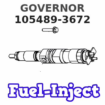
Information governor
BOSCH
9 420 613 707
9420613707
ZEXEL
105489-3672
1054893672
Rating:
Scheme ###:
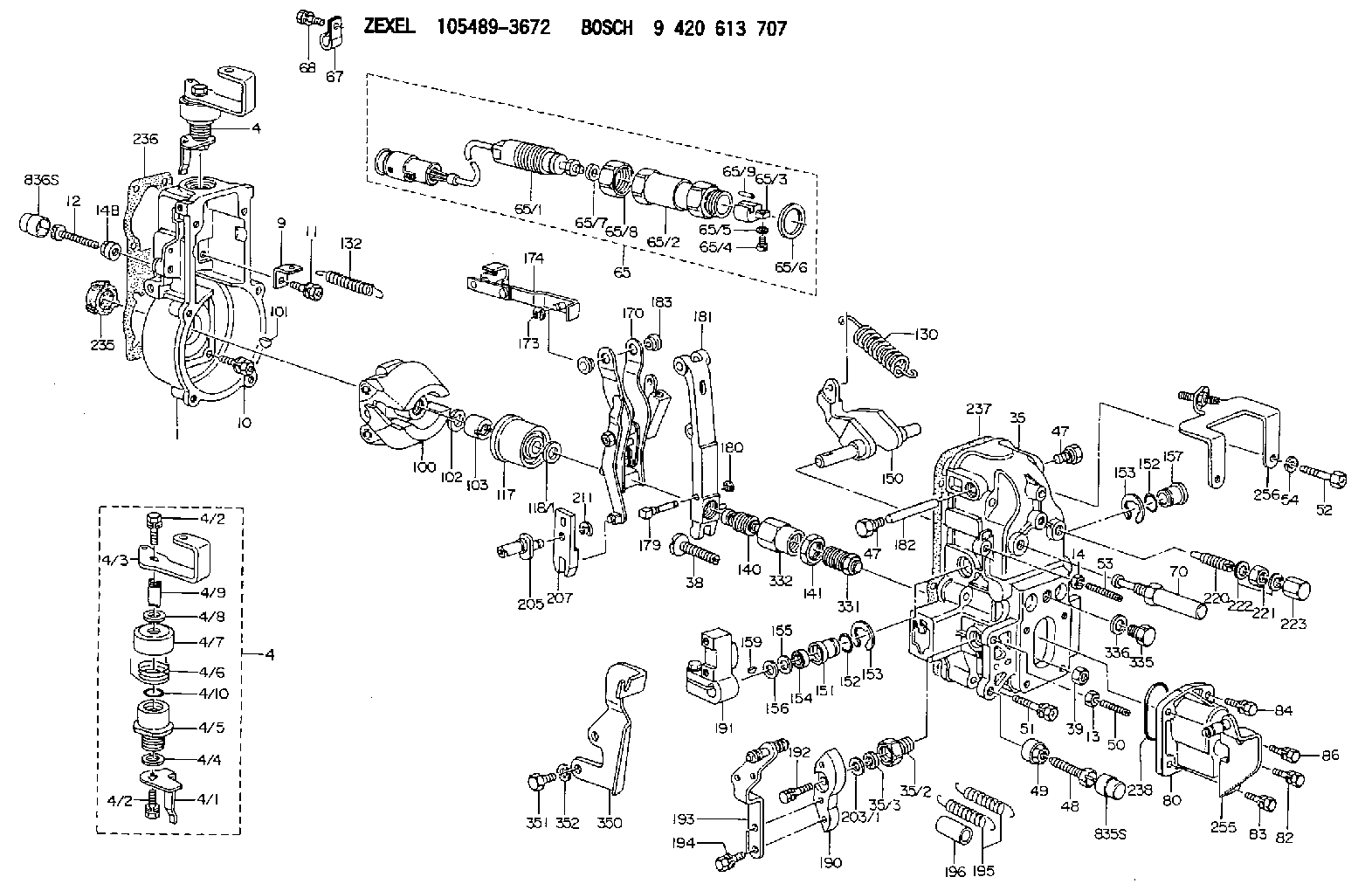
| 1. | [1] | 154004-1300 | GOVERNOR HOUSING |
| 4. | [1] | 154380-4320 | CONTROL LEVER |
| 4. | [1] | 154380-4320 | CONTROL LEVER |
| 4/1. | [1] | 154304-6200 | CONTROL LEVER |
| 4/2. | [2] | 154352-2000 | BLEEDER SCREW |
| 4/2. | [2] | 154352-2000 | BLEEDER SCREW |
| 4/3. | [1] | 154380-4300 | CONTROL LEVER |
| 4/4. | [1] | 029311-0230 | SHIM D18&10.3T0.5 |
| 4/5. | [1] | 154321-1500 | BUSHING |
| 4/6. | [1] | 154327-4100 | COILED SPRING |
| 4/7. | [1] | 154322-0100 | CAP |
| 4/8. | [1] | 029311-0220 | SHIM D18&10.3T0.2 |
| 4/9. | [1] | 154324-2700 | LEVER SHAFT |
| 4/10. | [1] | 029631-0030 | O-RING &9.8W2.3 |
| 9. | [1] | 154353-5601 | PLATE |
| 10. | [4] | 020106-2040 | BLEEDER SCREW M6P1L20 |
| 11. | [4] | 020106-1840 | BLEEDER SCREW M6P1L18 |
| 12. | [1] | 154010-7400 | BLEEDER SCREW M8P1.25L55 |
| 13. | [1] | 013020-6040 | UNION NUT M6P1H5 |
| 14. | [1] | 154011-0100 | HEXAGON NUT |
| 14B. | [1] | 154011-2300 | UNION NUT |
| 35. | [1] | 154515-4020 | GOVERNOR COVER |
| 35/2. | [1] | 154321-2000 | BUSHING |
| 35/3. | [1] | 029621-0080 | PACKING RING |
| 38. | [1] | 154031-3401 | FLAT-HEAD SCREW |
| 39. | [1] | 029201-0160 | UNION NUT |
| 47. | [2] | 154036-1800 | CAPSULE |
| 47. | [2] | 154036-1800 | CAPSULE |
| 48. | [1] | 154010-7700 | BLEEDER SCREW M10P1.25L51 |
| 48B. | [1] | 154010-7100 | BLEEDER SCREW M10P1.25L47 |
| 49. | [1] | 154011-2200 | UNION NUT |
| 50. | [1] | 155615-2300 | FLAT-HEAD SCREW |
| 51. | [5] | 020106-4540 | BLEEDER SCREW M6P1.0L45 |
| 52. | [2] | 010006-6040 | BLEEDER SCREW |
| 53. | [1] | 154010-1100 | FLAT-HEAD SCREW |
| 54. | [2] | 014110-6440 | LOCKING WASHER |
| 65. | [1] | 154610-3020 | RACK SENSOR ASSY |
| 65/1. | [1] | 479743-8920 | RACK SENSOR ASSY |
| 65/2. | [1] | 154614-4800 | JOINT CONNECTION |
| 65/3. | [1] | 154614-2900 | BLOCK |
| 65/4. | [1] | 010234-1040 | HEX-SOCKET-HEAD CAP SCREW |
| 65/5. | [1] | 014110-4440 | LOCKING WASHER |
| 65/6. | [1] | 026524-3040 | GASKET |
| 65/7. | [1] | 029310-6280 | SHIM D11.5&6.4T1.50 |
| 65/8. | [1] | 154614-1900 | UNION NUT |
| 65/9. | [1] | 154614-3300 | BEARING PIN |
| 67. | [1] | 154614-3600 | CLAMPING BAND |
| 68. | [1] | 020106-1240 | BLEEDER SCREW M6P1.0L12 |
| 70. | [1] | 154055-0520 | HEADLESS SCREW |
| 80. | [1] | 154063-9100 | COVER |
| 82. | [1] | 029020-6210 | BLEEDER SCREW |
| 83. | [1] | 029020-6240 | BLEEDER SCREW |
| 84. | [1] | 020006-1640 | BLEEDER SCREW M6P1L16 4T |
| 86. | [1] | 020006-1840 | BLEEDER SCREW M6P1L18 |
| 100. | [1] | 154100-9520 | FLYWEIGHT ASSEMBLY |
| 101. | [1] | 025803-1610 | WOODRUFF KEY |
| 102. | [1] | 029321-2020 | LOCKING WASHER |
| 103. | [1] | 139212-0000 | UNION NUT |
| 117. | [1] | 154123-2320 | SLIDING PIECE |
| 118/1. | [0] | 029311-0010 | SHIM D14&10.1T0.2 |
| 118/1. | [0] | 029311-0180 | SHIM D14&10.1T0.3 |
| 118/1. | [0] | 029311-0190 | SHIM D14&10.1T0.40 |
| 118/1. | [0] | 029311-0210 | SHIM D14&10.1T1 |
| 118/1. | [0] | 139410-0000 | SHIM D14.0&10.1T0.5 |
| 118/1. | [0] | 139410-0100 | SHIM D14.0&10.1T1.5 |
| 118/1. | [0] | 139410-3000 | SHIM D14&10.1T2.0 |
| 118/1. | [0] | 139410-3100 | SHIM D14&10.1T3.0 |
| 118/1. | [0] | 139410-3200 | SHIM D14&10.1T4.0 |
| 130. | [1] | 154150-8000 | GOVERNOR SPRING |
| 132. | [1] | 154154-3800 | COILED SPRING |
| 140. | [1] | 154183-1620 | HEADLESS SCREW |
| 141. | [1] | 139218-0100 | UNION NUT |
| 150. | [1] | 154200-5601 | SWIVELLING LEVER |
| 151. | [1] | 154200-5501 | BUSHING |
| 152. | [2] | 139700-0000 | O-RING |
| 152. | [2] | 139700-0000 | O-RING |
| 153. | [2] | 154354-3900 | LOCKING WASHER |
| 153. | [2] | 154354-3900 | LOCKING WASHER |
| 154. | [1] | 139610-0101 | PACKING RING |
| 155. | [1] | 139411-0100 | SHIM D22.0&12.0T0.40 |
| 156. | [0] | 139411-0200 | SHIM D18.0&12.0T0.10 |
| 156B. | [0] | 139411-0300 | SHIM D18.0&12.0T0.20 |
| 156C. | [0] | 139411-0400 | SHIM D18.0&12.0T0.30 |
| 157. | [1] | 154204-3500 | BUSHING |
| 159. | [1] | 025803-1310 | WOODRUFF KEY |
| 170. | [1] | 154217-7520 | FORK LEVER |
| 173. | [1] | 016010-0540 | LOCKING WASHER |
| 174. | [1] | 154230-8120 | STRAP |
| 179. | [1] | 154238-0701 | BEARING PIN |
| 180. | [1] | 016010-0540 | LOCKING WASHER |
| 181. | [1] | 154239-1520 | TENSIONING LEVER |
| 182. | [1] | 154237-1200 | BEARING PIN |
| 183. | [2] | 154237-1800 | BUSHING |
| 190. | [1] | 154360-2700 | CONTROL LEVER |
| 191. | [1] | 154340-4520 | CONTROL LEVER |
| 192. | [1] | 020006-1670 | BLEEDER SCREW M6P1L16 7T |
| 193. | [1] | 154385-3620 | CONTROL LEVER |
| 194. | [2] | 020006-1240 | BLEEDER SCREW M6P1L12 4T |
| 195. | [2] | 154332-8500 | COILED SPRING |
| 196. | [2] | 154156-2800 | TUBE |
| 203/1. | [0] | 029311-0640 | SHIM D26.0&10.2T0.95 |
| 203/1. | [0] | 029311-0650 | SHIM D26.0&10.2T0.20 |
| 203/1. | [0] | 029311-0660 | SHIM D26.0&10.2T0.25 |
| 203/1. | [0] | 029311-0670 | SHIM D26.0&10.2T0.30 |
| 203/1. | [0] | 029311-0680 | SHIM D26.0&10.2T0.35 |
| 203/1. | [0] | 029311-0690 | SHIM D26.0&10.2T0.40 |
| 203/1. | [0] | 029311-0700 | SHIM D26.0&10.2T0.50 |
| 203/1. | [0] | 139410-1400 | SHIM D26&10.2T0.7 |
| 203/1. | [0] | 139410-1500 | SHIM D26&10.2T0.9 |
| 203/1. | [0] | 139410-1600 | SHIM D26&10.2T0.8 |
| 203/1. | [0] | 139410-2700 | SHIM D26&10.2T0.6 |
| 205. | [1] | 154324-3600 | LEVER SHAFT |
| 207. | [1] | 154326-7420 | CONTROL LEVER |
| 211. | [1] | 016010-0840 | LOCKING WASHER |
| 220. | [1] | 154050-7720 | HEADLESS SCREW |
| 221. | [1] | 029201-2130 | UNION NUT M12P1.0H6 |
| 222. | [2] | 026512-1540 | GASKET D15.4&12.2T1.50 |
| 223. | [1] | 154159-1200 | CAP NUT |
| 235. | [1] | 155412-5300 | IMPELLER WHEEL |
| 236. | [1] | 154371-5600 | GASKET |
| 237. | [1] | 154390-0200 | GASKET |
| 238. | [1] | 139700-0100 | O-RING |
| 255. | [1] | 154373-6120 | BRACKET |
| 256. | [1] | 154373-9820 | BRACKET |
| 331. | [1] | 154179-7820 | HEADLESS SCREW |
| 332. | [1] | 139218-0200 | UNION NUT |
| 335. | [1] | 154352-2600 | CAPSULE |
| 336. | [1] | 029331-6030 | GASKET |
| 350. | [1] | 154374-0200 | BRACKET |
| 351. | [2] | 010010-1240 | BLEEDER SCREW M10P1.5L12 4T |
| 352. | [2] | 014111-0440 | LOCKING WASHER |
Include in #1:
106671-8553
as GOVERNOR
Cross reference number
Zexel num
Bosch num
Firm num
Name
Information:
1. Disconnect plug P11 to Throttle Position Sensor from receptacle J11. The locking ring helps identify P11 from J11. Check the connections for damaged wires or pins and corrosion. Also check that the pins are at the proper height in the connector. Check that the wires and pins are tight in the connectors by pulling (slightly) on each wire of each connector (including the breakout "T").2. Install 8T8726 Adapter (three pin breakout "T") between J11 and P11. Twist the locking rings to secure the connections.3. Connect the voltmeter as shown. Check for the appropriate voltages between the lettered "T" pins as explained in Steps 4 through 6.4. Check sensor supply voltage.Pin A (+) to pin B (ground) system voltage should be approximately 12 volts DC with key on (no accessories). Minimum voltage is 11.0 volts DC. While cranking, the voltage should be 8 to 12 volts DC. Diagnosis - Using the truck wiring schematic, check wires A and B and connections from J11 through the 10 A sensor fuse and the truck wiring harness back to the battery terminals for proper voltage.5. Check for poor power connection.If the voltage check between pins A and B is less than 11.0 volts with the key on, check the voltage drop from pin B to the negative battery post while cranking. For this test, the common lead (black) should be connected to the negative battery post first. Then place the positive (red) lead into pin B. (Pin B is chassis ground). Voltage should be less than .5 volts DC when cranking. Diagnosis - If the voltage drop is greater than .5 volts DC, check wire B and connections (including the battery post connections) from J11 to battery negative. Follow the truck wiring schematic to trace the electrical path from J11 to chassis ground.6. Check throttle signal.Pin C (throttle) to pin B (throttle return):* Less than 1.0 volt DC with the key on and the foot pedal in the low idle position.* More than 3.5 volts DC with the foot pedal in the high idle position. Diagnosis - If pin A to pin B voltage is proper and the voltage from pin C to pin B does not vary from low idle to high idle, check J11 pin C and socket connection. Check for broken throttle linkage from foot pedal to throttle position sensor. (Throttle position sensor may need adjustment or replacement. See Electronic Troubleshooting, 3406B (PEEC III) Diesel Truck Engine, Form No. SENR5147, or the Testing and Adjusting section in Systems Operation, Testing and Adjusting, 3406B (PEEC III) Diesel Truck Engine, Form No. SENR5146. Caterpillar supplied part, but initial adjustment is OEM responsibility.) Diagnostic code 32, Throttle Position Sensor Fault, will be generated if the throttle signal is not received by the ECM for at least one half second. This will limit engine RPM to low idle.7. Restore connections.Disconnect breakout "T" and reconnect P11 to J11. Secure the locking ring.If problem has not been resolved, proceed to the next connector