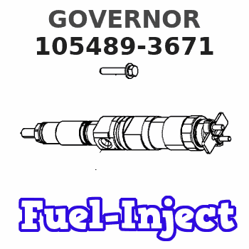
Information governor
BOSCH
F 019 Z9E 724
f019z9e724
ZEXEL
105489-3671
1054893671
Rating:
Scheme ###:
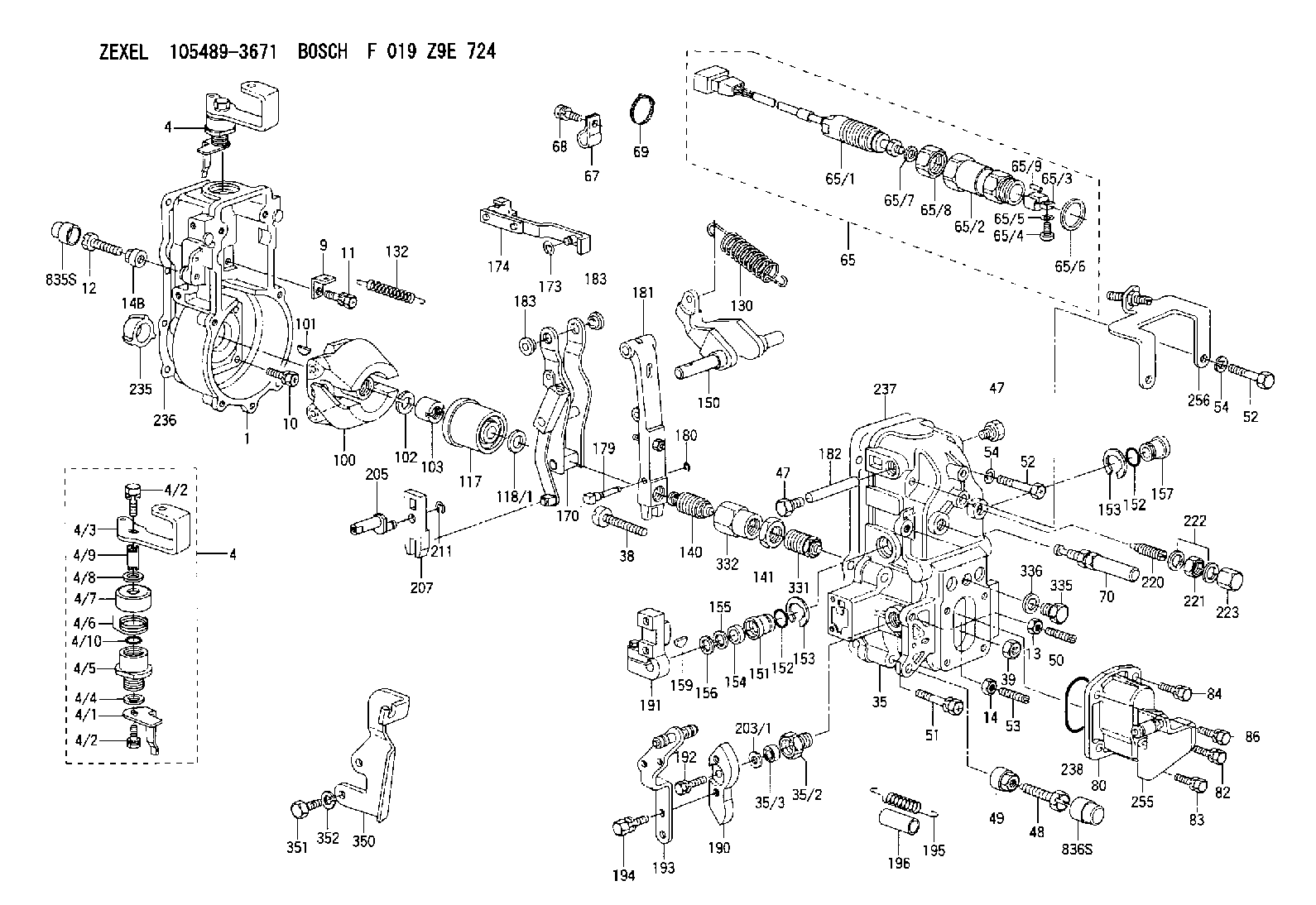
| 1. | [1] | 154004-1300 | GOVERNOR HOUSING |
| 4. | [1] | 154380-4320 | CONTROL LEVER |
| 4. | [1] | 154380-4320 | CONTROL LEVER |
| 4/1. | [1] | 154304-6200 | CONTROL LEVER |
| 4/2. | [2] | 154352-2000 | BLEEDER SCREW |
| 4/2. | [2] | 154352-2000 | BLEEDER SCREW |
| 4/3. | [1] | 154380-4300 | CONTROL LEVER |
| 4/4. | [1] | 029311-0230 | SHIM D18&10.3T0.5 |
| 4/5. | [1] | 154321-1500 | BUSHING |
| 4/6. | [1] | 154327-4100 | COILED SPRING |
| 4/7. | [1] | 154322-0100 | CAP |
| 4/8. | [1] | 029311-0220 | SHIM D18&10.3T0.2 |
| 4/9. | [1] | 154324-2700 | LEVER SHAFT |
| 4/10. | [1] | 029631-0030 | O-RING &9.8W2.3 |
| 9. | [1] | 154353-5601 | PLATE |
| 10. | [4] | 020106-2040 | BLEEDER SCREW M6P1L20 |
| 11. | [4] | 020106-1840 | BLEEDER SCREW M6P1L18 |
| 12. | [1] | 154010-7400 | BLEEDER SCREW M8P1.25L55 |
| 13. | [1] | 013020-6040 | UNION NUT M6P1H5 |
| 14. | [1] | 154011-0100 | HEXAGON NUT |
| 14B. | [1] | 154011-2300 | UNION NUT |
| 35. | [1] | 154515-4020 | GOVERNOR COVER |
| 35/2. | [1] | 154321-2000 | BUSHING |
| 35/3. | [1] | 029621-0080 | PACKING RING |
| 38. | [1] | 154031-3401 | FLAT-HEAD SCREW |
| 39. | [1] | 029201-0160 | UNION NUT |
| 47. | [2] | 154036-1800 | CAPSULE |
| 47. | [2] | 154036-1800 | CAPSULE |
| 48. | [1] | 154010-7700 | BLEEDER SCREW M10P1.25L51 |
| 48B. | [1] | 154010-7100 | BLEEDER SCREW M10P1.25L47 |
| 49. | [1] | 154011-2200 | UNION NUT |
| 50. | [1] | 155615-2300 | FLAT-HEAD SCREW |
| 51. | [5] | 020106-4540 | BLEEDER SCREW M6P1.0L45 |
| 52. | [2] | 010006-6040 | BLEEDER SCREW |
| 52. | [2] | 010006-6040 | BLEEDER SCREW |
| 53. | [1] | 154010-1100 | FLAT-HEAD SCREW |
| 54. | [2] | 014110-6440 | LOCKING WASHER |
| 54. | [2] | 014110-6440 | LOCKING WASHER |
| 65. | [1] | 154610-3020 | RACK SENSOR ASSY |
| 65/1. | [1] | 479743-8920 | RACK SENSOR ASSY |
| 65/2. | [1] | 154614-4800 | JOINT CONNECTION |
| 65/3. | [1] | 154614-2900 | BLOCK |
| 65/4. | [1] | 010234-1040 | HEX-SOCKET-HEAD CAP SCREW |
| 65/5. | [1] | 014110-4440 | LOCKING WASHER |
| 65/6. | [1] | 026524-3040 | GASKET |
| 65/7. | [1] | 029310-6280 | SHIM D11.5&6.4T1.50 |
| 65/8. | [1] | 154614-1900 | UNION NUT |
| 65/9. | [1] | 154614-3300 | BEARING PIN |
| 67. | [1] | 154614-3600 | CLAMPING BAND |
| 68. | [1] | 020106-1240 | BLEEDER SCREW M6P1.0L12 |
| 69. | [2] | 148650-0000 | BINDER |
| 70. | [1] | 154055-0520 | HEADLESS SCREW |
| 80. | [1] | 154063-9100 | COVER |
| 82. | [1] | 029020-6210 | BLEEDER SCREW |
| 83. | [1] | 029020-6240 | BLEEDER SCREW |
| 84. | [1] | 020006-1640 | BLEEDER SCREW M6P1L16 4T |
| 86. | [1] | 020006-1840 | BLEEDER SCREW M6P1L18 |
| 100. | [1] | 154100-9520 | FLYWEIGHT ASSEMBLY |
| 101. | [1] | 025803-1610 | WOODRUFF KEY |
| 102. | [1] | 029321-2020 | LOCKING WASHER |
| 103. | [1] | 139212-0000 | UNION NUT |
| 117. | [1] | 154123-2320 | SLIDING PIECE |
| 118/1. | [0] | 029311-0010 | SHIM D14&10.1T0.2 |
| 118/1. | [0] | 029311-0180 | SHIM D14&10.1T0.3 |
| 118/1. | [0] | 029311-0190 | SHIM D14&10.1T0.40 |
| 118/1. | [0] | 029311-0210 | SHIM D14&10.1T1 |
| 118/1. | [0] | 139410-0000 | SHIM D14.0&10.1T0.5 |
| 118/1. | [0] | 139410-0100 | SHIM D14.0&10.1T1.5 |
| 118/1. | [0] | 139410-3000 | SHIM D14&10.1T2.0 |
| 118/1. | [0] | 139410-3100 | SHIM D14&10.1T3.0 |
| 118/1. | [0] | 139410-3200 | SHIM D14&10.1T4.0 |
| 130. | [1] | 154150-8000 | GOVERNOR SPRING |
| 132. | [1] | 154154-3800 | COILED SPRING |
| 140. | [1] | 154183-1620 | HEADLESS SCREW |
| 141. | [1] | 139218-0100 | UNION NUT |
| 150. | [1] | 154200-5601 | SWIVELLING LEVER |
| 151. | [1] | 154200-5501 | BUSHING |
| 152. | [2] | 139700-0000 | O-RING |
| 152. | [2] | 139700-0000 | O-RING |
| 153. | [2] | 154354-3900 | LOCKING WASHER |
| 153. | [2] | 154354-3900 | LOCKING WASHER |
| 154. | [1] | 139610-0101 | PACKING RING |
| 155. | [1] | 139411-0100 | SHIM D22.0&12.0T0.40 |
| 156. | [0] | 139411-0200 | SHIM D18.0&12.0T0.10 |
| 156B. | [0] | 139411-0300 | SHIM D18.0&12.0T0.20 |
| 156C. | [0] | 139411-0400 | SHIM D18.0&12.0T0.30 |
| 157. | [1] | 154204-3500 | BUSHING |
| 159. | [1] | 025803-1310 | WOODRUFF KEY |
| 170. | [1] | 154217-7520 | FORK LEVER |
| 173. | [1] | 016010-0540 | LOCKING WASHER |
| 174. | [1] | 154230-8120 | STRAP |
| 179. | [1] | 154238-0701 | BEARING PIN |
| 180. | [1] | 016010-0540 | LOCKING WASHER |
| 181. | [1] | 154239-1520 | TENSIONING LEVER |
| 182. | [1] | 154237-1200 | BEARING PIN |
| 183. | [2] | 154237-1800 | BUSHING |
| 183. | [2] | 154237-1800 | BUSHING |
| 190. | [1] | 154360-2700 | CONTROL LEVER |
| 191. | [1] | 154340-4520 | CONTROL LEVER |
| 192. | [1] | 020006-1670 | BLEEDER SCREW M6P1L16 7T |
| 193. | [1] | 154385-3620 | CONTROL LEVER |
| 194. | [2] | 020006-1240 | BLEEDER SCREW M6P1L12 4T |
| 195. | [2] | 154332-5900 | COILED SPRING |
| 196. | [2] | 154156-2800 | TUBE |
| 203/1. | [0] | 029311-0640 | SHIM D26.0&10.2T0.95 |
| 203/1. | [0] | 029311-0650 | SHIM D26.0&10.2T0.20 |
| 203/1. | [0] | 029311-0660 | SHIM D26.0&10.2T0.25 |
| 203/1. | [0] | 029311-0670 | SHIM D26.0&10.2T0.30 |
| 203/1. | [0] | 029311-0680 | SHIM D26.0&10.2T0.35 |
| 203/1. | [0] | 029311-0690 | SHIM D26.0&10.2T0.40 |
| 203/1. | [0] | 029311-0700 | SHIM D26.0&10.2T0.50 |
| 203/1. | [0] | 139410-1400 | SHIM D26&10.2T0.7 |
| 203/1. | [0] | 139410-1500 | SHIM D26&10.2T0.9 |
| 203/1. | [0] | 139410-1600 | SHIM D26&10.2T0.8 |
| 203/1. | [0] | 139410-2700 | SHIM D26&10.2T0.6 |
| 205. | [1] | 154324-3600 | LEVER SHAFT |
| 207. | [1] | 154326-7420 | CONTROL LEVER |
| 211. | [1] | 016010-0840 | LOCKING WASHER |
| 220. | [1] | 154050-7720 | HEADLESS SCREW |
| 221. | [1] | 029201-2130 | UNION NUT M12P1.0H6 |
| 222. | [2] | 026512-1540 | GASKET D15.4&12.2T1.50 |
| 223. | [1] | 154159-1200 | CAP NUT |
| 235. | [1] | 155412-5300 | IMPELLER WHEEL |
| 236. | [1] | 154371-5600 | GASKET |
| 237. | [1] | 154390-0200 | GASKET |
| 238. | [1] | 139700-0100 | O-RING |
| 255. | [1] | 154373-6120 | BRACKET |
| 256. | [1] | 154373-9820 | BRACKET |
| 331. | [1] | 154179-7820 | HEADLESS SCREW |
| 332. | [1] | 139218-0200 | UNION NUT |
| 335. | [1] | 154352-2600 | CAPSULE |
| 336. | [1] | 029331-6030 | GASKET |
| 350. | [1] | 154374-0200 | BRACKET |
| 351. | [2] | 010010-1240 | BLEEDER SCREW M10P1.5L12 4T |
| 352. | [2] | 014111-0440 | LOCKING WASHER |
| 835S. | [1] | 154062-1700 | CAP D20L32 |
| 836S. | [1] | 154062-1800 | CAP D20L27 |
Include in #1:
106671-8551
as GOVERNOR
Cross reference number
Zexel num
Bosch num
Firm num
Name
Information:
1. Disconnect plug P7 from receptacle J7. Check the connections for damaged wires or pins and corrosion. Also check that the pins are at the proper height in the connector. Check that the wires and pins are tight in the connectors by pulling (slightly) on each wire of each connector (including the breakout "T").2. Install the 9X1160 Adapter (forty pin breakout "T") between J7 and P7 and secure the connections.3. Connect the voltmeter as shown. Check for the appropriate voltages between the lettered "T" pins as explained in Steps 4 through 18.4. Check system voltage.Pin 1 (+) to pin 2 (ground) system voltage should be approximately 12 volts DC with key on (no accessories). Minimum voltage is 11.0 volts DC. While cranking the voltage should be 8 to 12 volts DC. Diagnosis - Using the truck wiring schematic, check wires 1 and 2 and connections from J7 through the truck wiring harness back to the battery terminals for proper voltage.5. Check voltage drop from battery.If the voltage check between pins 1 and 2 on P7 is less than 11.0 volts with the key on, check the voltage drop from pin 2 of the J7 connector to the negative battery post while cranking. For this test, the common lead (black) should be connected to the negative battery post first. Then place the positive (red) lead into pin 2. (Pin 2 is chassis ground). Voltage should be less than .5 volts DC when cranking. Diagnosis - If voltage drop is greater than .5 volts DC, check wire 2 and connections (including the battery post connections) from J7 to battery negative.6. Parking BrakePin 11 (parking brake) to 2 (ground):* Less than .5 volts DC with the key on and parking brake applied.* More than 4.5 volts DC with the key on and parking brake released. Diagnosis - Disconnect breakout "T" and check the individual switch circuits for open, ground or faulty switch. Switch circuit must have less than 10 ohms resistance and more than 20,000 ohms resistance to chassis ground.7. Check brake switch.Pin 30 (brake switch) to 2:* Less than .5 volts DC with the key on.* More than 4.5 volts DC with brake pedal applied and the key on. Diagnosis - Disconnect breakout "T" and check the individual switch circuits for open, ground or faulty switch. Switch circuit must have less than 2.5 ohms resistance and more than 5000 ohms resistance to chassis ground.8. Check vehicle speed buffer.When testing for speedometer problems on trucks that have a single sensor with a single winding for vehicle speed, also follow J14 tests 6, 7 and 8.A. Disconnect the two buffer input wires from the Vehicle Speed Sensor. Using a long jumper wire, connect the white input wire to P7 Pin 1 (+ battery).* With key ON, engine OFF, measure voltage from P7 Pin 33 (vehicle speed) and P7