Information governor
BOSCH
9 420 614 455
9420614455
ZEXEL
105489-3595
1054893595
Rating:
Scheme ###:
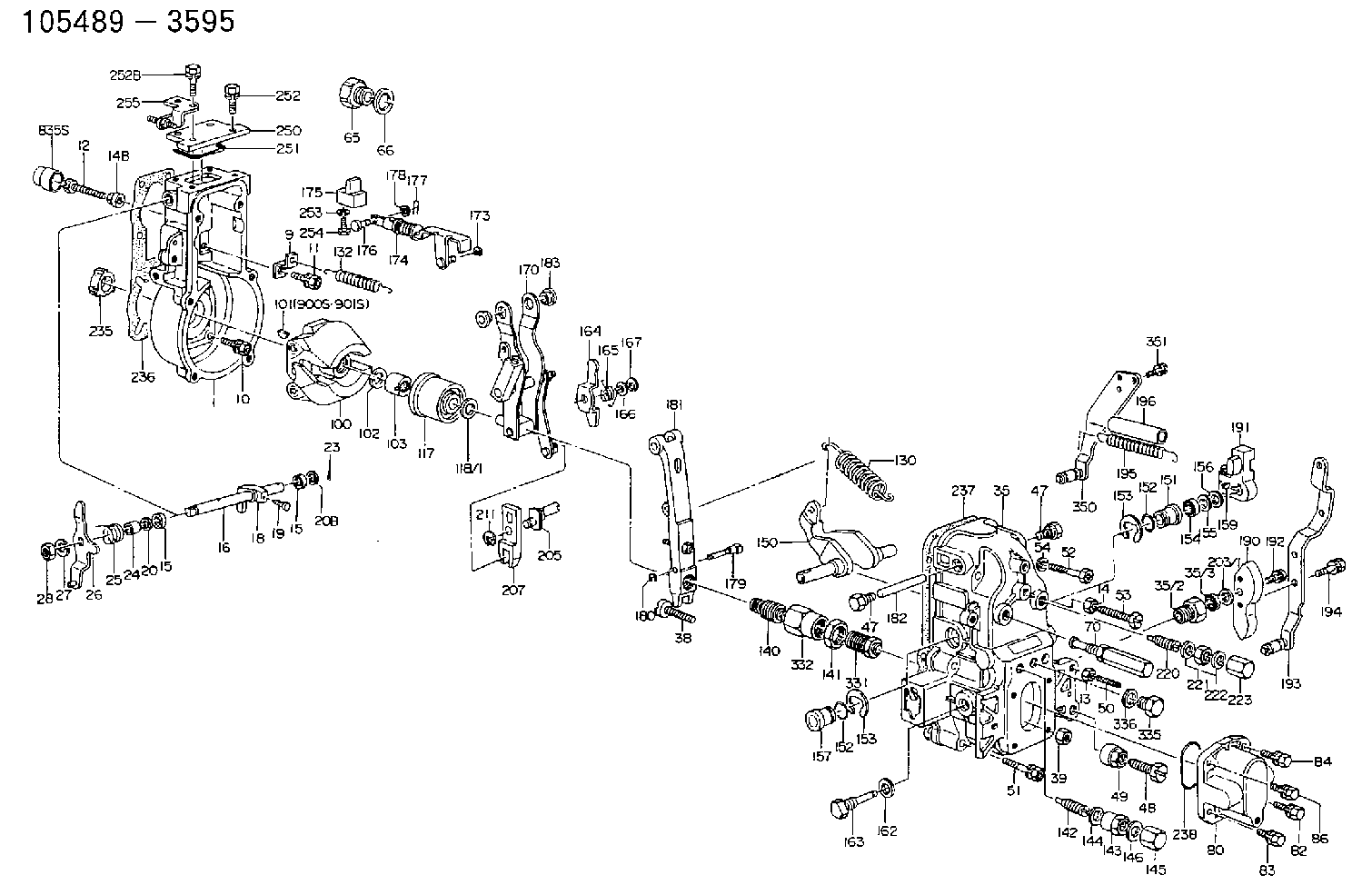
| 1. | [1] | 154004-4621 | GOVERNOR HOUSING |
| 9. | [1] | 154353-5601 | PLATE |
| 10. | [4] | 020106-2040 | BLEEDER SCREW M6P1L20 |
| 11. | [4] | 020106-1840 | BLEEDER SCREW M6P1L18 |
| 12. | [1] | 154010-7300 | BLEEDER SCREW M8P1.25L60 |
| 13. | [1] | 013020-6040 | UNION NUT M6P1H5 |
| 14. | [1] | 154011-0100 | HEXAGON NUT |
| 14B. | [1] | 154011-2300 | UNION NUT |
| 15. | [2] | 029620-8050 | PACKING RING |
| 15. | [2] | 029620-8050 | PACKING RING |
| 16. | [1] | 155004-3600 | LEVER SHAFT |
| 18. | [1] | 155003-2401 | CONTROL LEVER |
| 19. | [1] | 155006-0700 | BLEEDER SCREW |
| 20. | [1] | 139308-0900 | PLAIN WASHER D16&8T1 |
| 20B. | [1] | 139308-1000 | PLAIN WASHER D16&8T1.5 |
| 23. | [1] | 025520-1210 | SPLIT PIN |
| 24. | [1] | 154206-2000 | BUSHING |
| 25. | [1] | 154327-9000 | COILED SPRING |
| 26. | [1] | 154381-4220 | CONTROL LEVER |
| 27. | [1] | 014110-8440 | LOCKING WASHER |
| 28. | [1] | 013020-8040 | UNION NUT M8P1.25H7 |
| 29. | [1] | 139408-1400 | SHIM |
| 29B. | [0] | 139408-1400 | SHIM |
| 29C. | [0] | 139408-1500 | SHIM |
| 35. | [1] | 154516-2120 | GOVERNOR COVER |
| 35/2. | [1] | 154321-2000 | BUSHING |
| 35/3. | [1] | 139610-0600 | PACKING RING |
| 38. | [1] | 154031-3401 | FLAT-HEAD SCREW |
| 39. | [1] | 029201-0160 | UNION NUT |
| 47. | [2] | 154036-1800 | CAPSULE |
| 47. | [2] | 154036-1800 | CAPSULE |
| 48. | [1] | 154010-7100 | BLEEDER SCREW M10P1.25L47 |
| 48B. | [1] | 154010-5500 | BLEEDER SCREW M10P1.25L42 |
| 49. | [1] | 154011-2200 | UNION NUT |
| 50. | [1] | 155615-2300 | FLAT-HEAD SCREW |
| 51. | [5] | 020106-4540 | BLEEDER SCREW M6P1.0L45 |
| 52. | [2] | 029010-6850 | BLEEDER SCREW |
| 53. | [1] | 154010-3100 | BLEEDER SCREW |
| 54. | [2] | 014110-6440 | LOCKING WASHER |
| 65. | [1] | 155404-1700 | CAP |
| 66. | [1] | 026524-3040 | GASKET |
| 70. | [1] | 154055-1520 | HEADLESS SCREW |
| 80. | [1] | 154063-4100 | COVER |
| 82. | [1] | 029020-6210 | BLEEDER SCREW |
| 83. | [1] | 029020-6210 | BLEEDER SCREW |
| 84. | [1] | 020006-1640 | BLEEDER SCREW M6P1L16 4T |
| 86. | [1] | 020006-1640 | BLEEDER SCREW M6P1L16 4T |
| 100. | [1] | 154100-9220 | FLYWEIGHT ASSEMBLY |
| 101. | [1] | 025803-1310 | WOODRUFF KEY |
| 102. | [1] | 029321-2020 | LOCKING WASHER |
| 103. | [1] | 139212-0000 | UNION NUT |
| 117. | [1] | 154123-2320 | SLIDING PIECE |
| 118/1. | [0] | 029311-0010 | SHIM D14&10.1T0.2 |
| 118/1. | [0] | 029311-0180 | SHIM D14&10.1T0.3 |
| 118/1. | [0] | 029311-0190 | SHIM D14&10.1T0.40 |
| 118/1. | [0] | 029311-0210 | SHIM D14&10.1T1 |
| 118/1. | [0] | 139410-0000 | SHIM D14.0&10.1T0.5 |
| 118/1. | [0] | 139410-0100 | SHIM D14.0&10.1T1.5 |
| 118/1. | [0] | 139410-3000 | SHIM D14&10.1T2.0 |
| 118/1. | [0] | 139410-3100 | SHIM D14&10.1T3.0 |
| 118/1. | [0] | 139410-3200 | SHIM D14&10.1T4.0 |
| 130. | [1] | 154150-7900 | GOVERNOR SPRING |
| 132. | [1] | 154154-4600 | COILED SPRING |
| 140. | [1] | 154183-8220 | HEADLESS SCREW |
| 141. | [1] | 139218-0100 | UNION NUT |
| 142. | [1] | 154242-5220 | HEADLESS SCREW |
| 143. | [1] | 154242-5400 | UNION NUT |
| 144. | [1] | 026516-2040 | GASKET D19.9&16.2T1 |
| 145. | [1] | 154159-1800 | CAP NUT |
| 146. | [1] | 029331-6130 | GASKET |
| 150. | [1] | 154200-5401 | SWIVELLING LEVER |
| 151. | [1] | 154200-5501 | BUSHING |
| 152. | [2] | 139700-0000 | O-RING |
| 152. | [2] | 139700-0000 | O-RING |
| 153. | [2] | 154354-3900 | LOCKING WASHER |
| 153. | [2] | 154354-3900 | LOCKING WASHER |
| 154. | [1] | 139610-0101 | PACKING RING |
| 155. | [1] | 139411-0100 | SHIM D22.0&12.0T0.40 |
| 156. | [0] | 139411-0200 | SHIM D18.0&12.0T0.10 |
| 156B. | [0] | 139411-0300 | SHIM D18.0&12.0T0.20 |
| 156C. | [0] | 139411-0400 | SHIM D18.0&12.0T0.30 |
| 157. | [1] | 154204-3500 | BUSHING |
| 159. | [1] | 025803-1310 | WOODRUFF KEY |
| 162. | [1] | 029331-6050 | GASKET |
| 163. | [1] | 154401-3201 | BLEEDER SCREW |
| 164. | [1] | 154243-0720 | CONTROL LEVER |
| 165. | [1] | 154327-6000 | COILED SPRING |
| 166. | [1] | 029310-8320 | SHIM D16.5&8T0.2 |
| 167. | [1] | 154356-3600 | LOCKING WASHER |
| 170. | [1] | 154217-7020 | FORK LEVER |
| 173. | [1] | 016010-0540 | LOCKING WASHER |
| 174. | [1] | 154234-3220 | STRAP |
| 175. | [1] | 154232-2323 | CONNECTOR |
| 176. | [1] | 159231-4900 | BEARING PIN |
| 177. | [1] | 155402-3800 | SAFETY PIN |
| 178. | [1] | 029310-5170 | SHIM D8&5.3T0.5 |
| 179. | [1] | 154238-0201 | BEARING PIN |
| 180. | [1] | 016010-0540 | LOCKING WASHER |
| 181. | [1] | 154239-0420 | TENSIONING LEVER |
| 182. | [1] | 154237-1200 | BEARING PIN |
| 183. | [2] | 154237-1300 | BUSHING |
| 190. | [1] | 154360-2800 | CONTROL LEVER |
| 191. | [1] | 154340-4320 | CONTROL LEVER |
| 192. | [1] | 020006-1670 | BLEEDER SCREW M6P1L16 7T |
| 193. | [1] | 154385-7620 | CONTROL LEVER |
| 194. | [2] | 020006-1240 | BLEEDER SCREW M6P1L12 4T |
| 195. | [2] | 154332-9200 | COILED SPRING |
| 196. | [2] | 154156-3601 | TUBE |
| 203/1. | [0] | 029311-0640 | SHIM D26.0&10.2T0.95 |
| 203/1. | [0] | 029311-0650 | SHIM D26.0&10.2T0.20 |
| 203/1. | [0] | 029311-0660 | SHIM D26.0&10.2T0.25 |
| 203/1. | [0] | 029311-0670 | SHIM D26.0&10.2T0.30 |
| 203/1. | [0] | 029311-0680 | SHIM D26.0&10.2T0.35 |
| 203/1. | [0] | 029311-0690 | SHIM D26.0&10.2T0.40 |
| 203/1. | [0] | 029311-0700 | SHIM D26.0&10.2T0.50 |
| 203/1. | [0] | 139410-1400 | SHIM D26&10.2T0.7 |
| 203/1. | [0] | 139410-1500 | SHIM D26&10.2T0.9 |
| 203/1. | [0] | 139410-1600 | SHIM D26&10.2T0.8 |
| 203/1. | [0] | 139410-2700 | SHIM D26&10.2T0.6 |
| 205. | [1] | 154324-4100 | LEVER SHAFT |
| 207. | [1] | 154326-0300 | CONTROL LEVER |
| 211. | [1] | 016010-0840 | LOCKING WASHER |
| 220. | [1] | 154050-8220 | HEADLESS SCREW |
| 221. | [1] | 029201-2140 | UNION NUT |
| 222. | [2] | 026512-1540 | GASKET D15.4&12.2T1.50 |
| 223. | [1] | 154159-1200 | CAP NUT |
| 235. | [1] | 155412-5200 | IMPELLER WHEEL |
| 236. | [1] | 154371-5600 | GASKET |
| 237. | [1] | 154390-0200 | GASKET |
| 238. | [1] | 139700-0100 | O-RING |
| 250. | [1] | 154063-9800 | COVER |
| 251. | [1] | 154358-2500 | SEAL RING |
| 252. | [2] | 020006-1640 | BLEEDER SCREW M6P1L16 4T |
| 252B. | [2] | 020006-2040 | BLEEDER SCREW M6P1L20 4T |
| 253. | [1] | 029320-5020 | LOCKING WASHER |
| 254. | [1] | 010535-1040 | FLAT-HEAD SCREW M5P0.8L10 |
| 255. | [1] | 154373-5620 | BRACKET |
| 331. | [1] | 154179-9920 | HEADLESS SCREW |
| 332. | [1] | 139218-0200 | UNION NUT |
| 335. | [1] | 154352-2600 | CAPSULE |
| 336. | [1] | 029331-6030 | GASKET |
| 350. | [1] | 154373-9520 | BRACKET |
| 351. | [3] | 029010-5340 | BLEEDER SCREW |
| 835S. | [2] | 154062-1700 | CAP D20L32 |
| 900S. | [1] | 025803-1310 | WOODRUFF KEY |
| 901S. | [1] | 025803-1610 | WOODRUFF KEY |
Cross reference number
Zexel num
Bosch num
Firm num
Name
Information:
Typical Example3. Loosen the clamps on breather tube (1), and pull it back for clearance. 4. Remove bolt (2) from the cover on the side of the cylinder block. 5. Remove the three bolts that hold cover (3) to the water pump. Remove cover (3) from the water pump. 6. Remove the two bolts, and remove elbow (4) from bonnet (5). Remove the two bolts, and remove bonnet (5) from the water pump. It is not necessary to remove bolts (6). These bolts only hold the cover to the timing gear cover.7. Remove six long bolts (7) that hold the water pump to the timing gear cover. Remove water pump (8).Install Water Pump
1. Check the O-ring seals and gaskets, and make replacements if needed. 2. Make sure O-ring seal (9) is in position on the water pump. Put water pump (8) into position in the timing gear cover. Install the bolts that hold the water pump in place. 3. Make sure the gaskets are in place. Connect bonnet (5) to the water pump. Connect elbow (4) to the bonnet. 4. Make sure O-ring seal (10) is in position, and install cover (3) on the water pump. 5. Install bolt (2) on the cover on the side of the engine. 6. Put breather tube (1) in position, and install the clamps that hold it.7. Install the altenator mounting group and alternator on the engine.8. Install the water temperature regulator and manifold. See the topic Install Water Temperature Regulator and Manifold.9. Fill the cooling system to the correct level. See the Maintenance Manual.Disassemble & Assemble Water Pump
Start By:a. remove water pump The water pump seal can be replaced without removing the water pump from the engine.An intermittent leakage of a small amount of coolant from the hole in the water pump housing is not an indication of a water pump seal failure. This is required to provide lubrication for the seal. Replace the water pump seal only if a large amount of leakage or a constant flow of coolant is observed draining from the water pump housing. 1. Remove O-ring seal (3) from adapter (4). Remove the adapter from housing (7). Remove the O-ring seal from the outside of the adapter.2. Remove bolt (1) and washer (2). Use tooling (A) to remove impeller (6) from shaft (13).3. Remove spring and seal (5) from the shaft.4. Remove four bolts (16) from retainer (12) that hold the shaft assembly to the pump housing. Remove O-ring seal (18) from housing (7).5. Remove gear and shaft assembly (17) from the housing. Remove bolt (15), retainer (14), and retainer (12) from the shaft assembly.6. Use a press to remove shaft (13) from the gear. Remove bearing (9), spacer (10), and bearing (11) from the shaft.7. Remove lip-type seal (8) from the housing.8. Turn the housing over, and remove ceramic ring (20) and seal (19) from the housing. The following steps are for the assembly of the water pump.9. Use 6V1541 Quick Cure Primer and clean