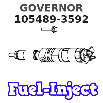
Information governor
BOSCH
9 420 612 140
9420612140
ZEXEL
105489-3592
1054893592
Rating:
Scheme ###:
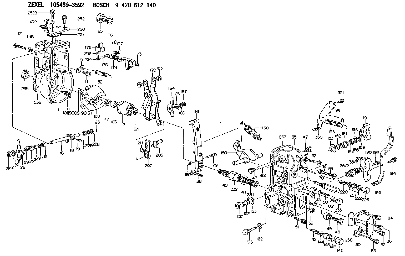
| 1. | [1] | 154004-4621 | GOVERNOR HOUSING |
| 9. | [1] | 154353-5601 | PLATE |
| 10. | [4] | 020106-2040 | BLEEDER SCREW M6P1L20 |
| 11. | [4] | 020106-1840 | BLEEDER SCREW M6P1L18 |
| 12. | [1] | 154010-7300 | BLEEDER SCREW M8P1.25L60 |
| 13. | [1] | 013020-6040 | UNION NUT M6P1H5 |
| 14. | [1] | 154011-0100 | HEXAGON NUT |
| 14B. | [1] | 154011-2300 | UNION NUT |
| 15. | [2] | 029620-8050 | PACKING RING |
| 15. | [2] | 029620-8050 | PACKING RING |
| 16. | [1] | 155004-3600 | LEVER SHAFT |
| 18. | [1] | 155003-2401 | CONTROL LEVER |
| 19. | [1] | 155006-0700 | BLEEDER SCREW |
| 20. | [1] | 139308-0900 | PLAIN WASHER D16&8T1 |
| 20B. | [1] | 139308-1000 | PLAIN WASHER D16&8T1.5 |
| 22B. | [0] | 029310-8050 | SHIM D13.5&8T0.5 |
| 22B. | [7] | 139408-1500 | SHIM |
| 23. | [1] | 025520-1210 | SPLIT PIN |
| 24. | [1] | 154206-2000 | BUSHING |
| 25. | [1] | 154327-9000 | COILED SPRING |
| 26. | [1] | 154381-4220 | CONTROL LEVER |
| 27. | [1] | 014110-8440 | LOCKING WASHER |
| 28. | [1] | 013020-8040 | UNION NUT M8P1.25H7 |
| 29. | [1] | 139408-1400 | SHIM |
| 29B. | [0] | 139408-1400 | SHIM |
| 29C. | [0] | 139408-1500 | SHIM |
| 35. | [1] | 154514-8220 | GOVERNOR COVER |
| 35/2. | [1] | 154321-2000 | BUSHING |
| 35/3. | [1] | 029621-0080 | PACKING RING |
| 38. | [1] | 154031-3401 | FLAT-HEAD SCREW |
| 39. | [1] | 029201-0160 | UNION NUT |
| 47. | [2] | 154036-1800 | CAPSULE |
| 47. | [2] | 154036-1800 | CAPSULE |
| 48. | [1] | 154010-7100 | BLEEDER SCREW M10P1.25L47 |
| 48B. | [1] | 154010-5500 | BLEEDER SCREW M10P1.25L42 |
| 49. | [1] | 154011-2200 | UNION NUT |
| 50. | [1] | 155615-2300 | FLAT-HEAD SCREW |
| 51. | [5] | 020106-4540 | BLEEDER SCREW M6P1.0L45 |
| 52. | [2] | 029010-6850 | BLEEDER SCREW |
| 53. | [1] | 154010-3100 | BLEEDER SCREW |
| 54. | [2] | 014110-6440 | LOCKING WASHER |
| 65. | [1] | 155404-1700 | CAP |
| 66. | [1] | 026524-3040 | GASKET |
| 70. | [1] | 154055-1520 | HEADLESS SCREW |
| 80. | [1] | 154063-4100 | COVER |
| 82. | [1] | 029020-6210 | BLEEDER SCREW |
| 83. | [1] | 029020-6210 | BLEEDER SCREW |
| 84. | [1] | 020006-1640 | BLEEDER SCREW M6P1L16 4T |
| 86. | [1] | 020006-1640 | BLEEDER SCREW M6P1L16 4T |
| 100. | [1] | 154100-9220 | FLYWEIGHT ASSEMBLY |
| 101. | [1] | 025803-1310 | WOODRUFF KEY |
| 102. | [1] | 029321-2020 | LOCKING WASHER |
| 103. | [1] | 139212-0000 | UNION NUT |
| 117. | [1] | 154123-2320 | SLIDING PIECE |
| 118/1. | [0] | 029311-0010 | SHIM D14&10.1T0.2 |
| 118/1. | [0] | 029311-0180 | SHIM D14&10.1T0.3 |
| 118/1. | [0] | 029311-0190 | SHIM D14&10.1T0.40 |
| 118/1. | [0] | 029311-0210 | SHIM D14&10.1T1 |
| 118/1. | [0] | 139410-0000 | SHIM D14.0&10.1T0.5 |
| 118/1. | [0] | 139410-0100 | SHIM D14.0&10.1T1.5 |
| 118/1. | [0] | 139410-3000 | SHIM D14&10.1T2.0 |
| 118/1. | [0] | 139410-3100 | SHIM D14&10.1T3.0 |
| 118/1. | [0] | 139410-3200 | SHIM D14&10.1T4.0 |
| 130. | [1] | 154150-7900 | GOVERNOR SPRING |
| 132. | [1] | 154154-4600 | COILED SPRING |
| 140. | [1] | 154183-8220 | HEADLESS SCREW |
| 141. | [1] | 139218-0100 | UNION NUT |
| 142. | [1] | 154242-5220 | HEADLESS SCREW |
| 143. | [1] | 154242-5400 | UNION NUT |
| 144. | [1] | 026516-2040 | GASKET D19.9&16.2T1 |
| 145. | [1] | 154159-1800 | CAP NUT |
| 146. | [1] | 029331-6130 | GASKET |
| 150. | [1] | 154200-5401 | SWIVELLING LEVER |
| 151. | [1] | 154200-5501 | BUSHING |
| 152. | [2] | 139700-0000 | O-RING |
| 152. | [2] | 139700-0000 | O-RING |
| 153. | [2] | 154354-3900 | LOCKING WASHER |
| 153. | [2] | 154354-3900 | LOCKING WASHER |
| 154. | [1] | 139610-0101 | PACKING RING |
| 155. | [1] | 139411-0100 | SHIM D22.0&12.0T0.40 |
| 156. | [0] | 139411-0200 | SHIM D18.0&12.0T0.10 |
| 156B. | [0] | 139411-0300 | SHIM D18.0&12.0T0.20 |
| 156C. | [0] | 139411-0400 | SHIM D18.0&12.0T0.30 |
| 157. | [1] | 154204-3500 | BUSHING |
| 159. | [1] | 025803-1310 | WOODRUFF KEY |
| 162. | [1] | 029331-6050 | GASKET |
| 163. | [1] | 154401-3201 | BLEEDER SCREW |
| 164. | [1] | 154243-0720 | CONTROL LEVER |
| 165. | [1] | 154327-6000 | COILED SPRING |
| 166. | [1] | 029310-8320 | SHIM D16.5&8T0.2 |
| 167. | [1] | 154356-3600 | LOCKING WASHER |
| 170. | [1] | 154217-7020 | FORK LEVER |
| 173. | [1] | 016010-0540 | LOCKING WASHER |
| 174. | [1] | 154234-3220 | STRAP |
| 175. | [1] | 154232-2323 | CONNECTOR |
| 176. | [1] | 159231-4900 | BEARING PIN |
| 177. | [1] | 155402-3800 | SAFETY PIN |
| 178. | [1] | 029310-5170 | SHIM D8&5.3T0.5 |
| 179. | [1] | 154238-0201 | BEARING PIN |
| 180. | [1] | 016010-0540 | LOCKING WASHER |
| 181. | [1] | 154239-0420 | TENSIONING LEVER |
| 182. | [1] | 154237-1200 | BEARING PIN |
| 183. | [2] | 154237-1300 | BUSHING |
| 190. | [1] | 154360-2800 | CONTROL LEVER |
| 191. | [1] | 154340-4320 | CONTROL LEVER |
| 192. | [1] | 020006-1670 | BLEEDER SCREW M6P1L16 7T |
| 193. | [1] | 154385-7620 | CONTROL LEVER |
| 194. | [2] | 020006-1240 | BLEEDER SCREW M6P1L12 4T |
| 195. | [2] | 154332-5600 | COILED SPRING |
| 196. | [2] | 154156-3600 | TUBE |
| 203/1. | [0] | 029311-0640 | SHIM D26.0&10.2T0.95 |
| 203/1. | [0] | 029311-0650 | SHIM D26.0&10.2T0.20 |
| 203/1. | [0] | 029311-0660 | SHIM D26.0&10.2T0.25 |
| 203/1. | [0] | 029311-0670 | SHIM D26.0&10.2T0.30 |
| 203/1. | [0] | 029311-0680 | SHIM D26.0&10.2T0.35 |
| 203/1. | [0] | 029311-0690 | SHIM D26.0&10.2T0.40 |
| 203/1. | [0] | 029311-0700 | SHIM D26.0&10.2T0.50 |
| 203/1. | [0] | 139410-1400 | SHIM D26&10.2T0.7 |
| 203/1. | [0] | 139410-1500 | SHIM D26&10.2T0.9 |
| 203/1. | [0] | 139410-1600 | SHIM D26&10.2T0.8 |
| 203/1. | [0] | 139410-2700 | SHIM D26&10.2T0.6 |
| 205. | [1] | 154324-4100 | LEVER SHAFT |
| 207. | [1] | 154326-0300 | CONTROL LEVER |
| 211. | [1] | 016010-0840 | LOCKING WASHER |
| 220. | [1] | 154050-8220 | HEADLESS SCREW |
| 221. | [1] | 029201-2140 | UNION NUT |
| 222. | [2] | 026512-1540 | GASKET D15.4&12.2T1.50 |
| 223. | [1] | 154159-1200 | CAP NUT |
| 235. | [1] | 155412-5200 | IMPELLER WHEEL |
| 236. | [1] | 154371-5600 | GASKET |
| 237. | [1] | 154390-0200 | GASKET |
| 238. | [1] | 139700-0100 | O-RING |
| 250. | [1] | 154063-9800 | COVER |
| 251. | [1] | 154358-2500 | SEAL RING |
| 252. | [2] | 020006-1640 | BLEEDER SCREW M6P1L16 4T |
| 252B. | [2] | 020006-2040 | BLEEDER SCREW M6P1L20 4T |
| 253. | [1] | 029320-5020 | LOCKING WASHER |
| 254. | [1] | 010535-1040 | FLAT-HEAD SCREW M5P0.8L10 |
| 255. | [1] | 154373-5620 | BRACKET |
| 331. | [1] | 154179-9920 | HEADLESS SCREW |
| 332. | [1] | 139218-0200 | UNION NUT |
| 335. | [1] | 154352-2600 | CAPSULE |
| 336. | [1] | 029331-6030 | GASKET |
| 350. | [1] | 154373-9520 | BRACKET |
| 351. | [3] | 029010-5340 | BLEEDER SCREW |
| 900S. | [1] | 025803-1310 | WOODRUFF KEY |
| 901S. | [1] | 025803-1610 | WOODRUFF KEY |
Include in #1:
106871-8952
as GOVERNOR
Cross reference number
Zexel num
Bosch num
Firm num
Name
Information:
Start By:a. disassemble governorb. remove fuel injection pumps 1. Remove the six lifters from the fuel pump housing.2. Remove rack (1) and camshaft (2) from the fuel pump housing. If necessary use a soft hammer to push the camshaft out the governor end. 3. Use tooling (A) and remove the three camshaft bearings from the fuel pump housing. 4. Remove rack bearing (4) and the other rack bearing from the fuel pump housing.5. Remove dowel (3) from the fuel pump housing. 6. Remove bolts (6), cover (5) and the gasket from the fuel pump housing.Assemble Fuel Injection Pump Housing
1. Install gasket (7) and cover (5) on the side of the fuel pump housing. 2. Use tooling (B) and install (D) shaped rack bearing into the automatic timing advance side of the fuel pump housing 87.0 0.5 mm (3.42 .02 in) from outside surface (X).3. The inside flat side diameter after assembly must be 11.178 0.050 mm (.440 .002 in) and the inside large diameter must be 12.767 0.058 mm (.503 .002 in). 4. Install dowel (3) in the fuel pump housing 6.0 0.5 mm (.24 .02 in) above the outside surface.5. Use tool group (C) and install the rack bearing into the fuel pump housing 7.16 0.13 mm (.282 .005 in) below the outside surface of the pump housing.6. The inside diameter of the bearing after assembly must be 12.746 0.045 mm (.502 .002 in). 7. Use tool group (A) and install the three camshaft bearings in the fuel pump housing with the oil holes in the bearings 30° 3° from the horizontal center line toward the plugged holes in the fuel pump housing.8. The inside diameter of all three bearings after assembly must be 68.339 0.038 mm (2.6905 .0015 in). 9. Make sure bearing (8) on automatic timing advance side is installed 1.0 0.5 mm (.04 .02 in) below surface (Y).10. Make sure middle bearing (9) is 218 0.3 mm (8.6 .01 in) below surface (Y). 11. Make sure bearing (10) governor side 1.00 0.25 mm (.04 .01 in) below the outside surface.12. Remove the plugs from the side of the fuel pump housing. The oil holes in the bearings must be in alignment with holes (11) in the fuel pump housing. If the bearings are not in alignment, remove them and install again. 13. Make an alignment of rack (1) and install it in the fuel pump housing.14. Install camshaft (2) in the fuel pump housing as shown.15. Install the six lifters in the fuel pump housing. Make sure the pins in the lifter are on the same side as the dowels in the fuel pump housing.End By:a. install fuel injection pumpsb. assemble governor
1. Install gasket (7) and cover (5) on the side of the fuel pump housing. 2. Use tooling (B) and install (D) shaped rack bearing into the automatic timing advance side of the fuel pump housing 87.0 0.5 mm (3.42 .02 in) from outside surface (X).3. The inside flat side diameter after assembly must be 11.178 0.050 mm (.440 .002 in) and the inside large diameter must be 12.767 0.058 mm (.503 .002 in). 4. Install dowel (3) in the fuel pump housing 6.0 0.5 mm (.24 .02 in) above the outside surface.5. Use tool group (C) and install the rack bearing into the fuel pump housing 7.16 0.13 mm (.282 .005 in) below the outside surface of the pump housing.6. The inside diameter of the bearing after assembly must be 12.746 0.045 mm (.502 .002 in). 7. Use tool group (A) and install the three camshaft bearings in the fuel pump housing with the oil holes in the bearings 30° 3° from the horizontal center line toward the plugged holes in the fuel pump housing.8. The inside diameter of all three bearings after assembly must be 68.339 0.038 mm (2.6905 .0015 in). 9. Make sure bearing (8) on automatic timing advance side is installed 1.0 0.5 mm (.04 .02 in) below surface (Y).10. Make sure middle bearing (9) is 218 0.3 mm (8.6 .01 in) below surface (Y). 11. Make sure bearing (10) governor side 1.00 0.25 mm (.04 .01 in) below the outside surface.12. Remove the plugs from the side of the fuel pump housing. The oil holes in the bearings must be in alignment with holes (11) in the fuel pump housing. If the bearings are not in alignment, remove them and install again. 13. Make an alignment of rack (1) and install it in the fuel pump housing.14. Install camshaft (2) in the fuel pump housing as shown.15. Install the six lifters in the fuel pump housing. Make sure the pins in the lifter are on the same side as the dowels in the fuel pump housing.End By:a. install fuel injection pumpsb. assemble governor