Information governor
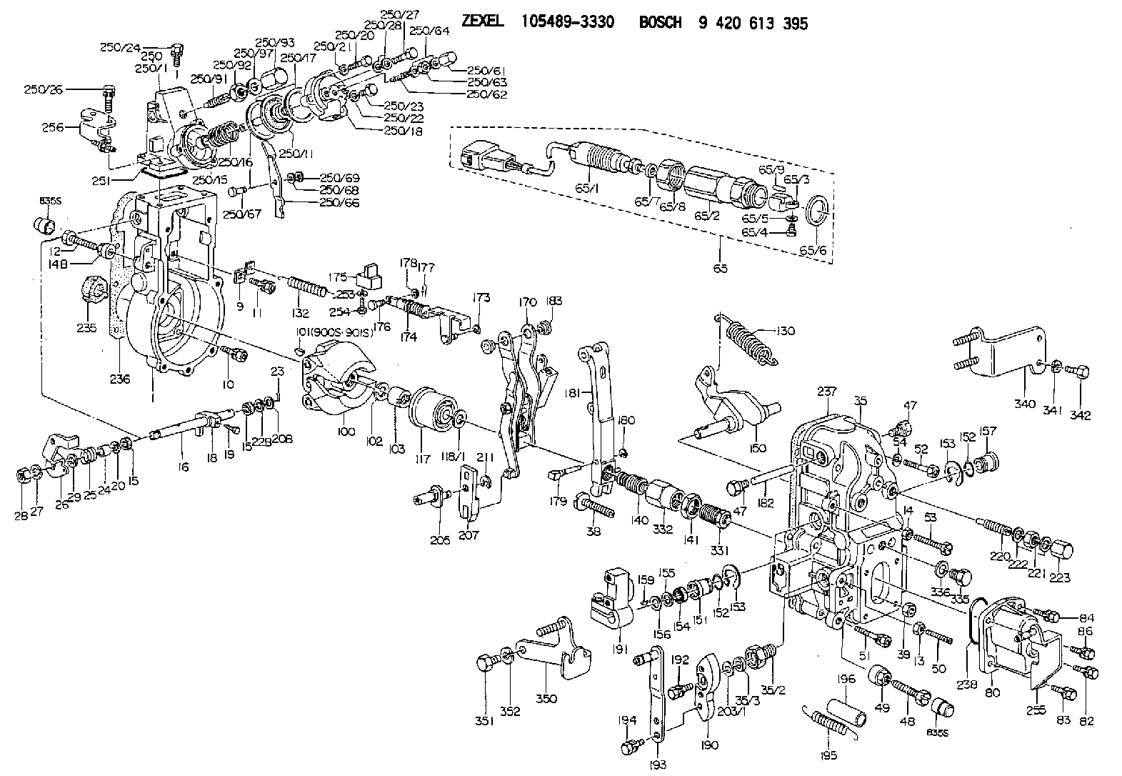
BOSCH
9 420 613 695
9420613695
ZEXEL
105489-3330
1054893330
Rating:
Scheme ###:
| 1. | [1] | 154004-6420 | GOVERNOR HOUSING |
| 9. | [1] | 154350-6000 | PLATE |
| 10. | [4] | 139006-4100 | BLEEDER SCREW |
| 11. | [4] | 139006-5800 | BLEEDER SCREW |
| 12. | [1] | 154010-7300 | BLEEDER SCREW M8P1.25L60 |
| 13. | [1] | 013020-6040 | UNION NUT M6P1H5 |
| 14. | [1] | 154011-0100 | HEXAGON NUT |
| 14B. | [1] | 154011-2300 | UNION NUT |
| 15. | [2] | 029620-8050 | PACKING RING |
| 15. | [2] | 029620-8050 | PACKING RING |
| 16. | [1] | 155004-3600 | LEVER SHAFT |
| 18. | [1] | 155003-3401 | CONTROL LEVER |
| 19. | [1] | 155006-0700 | BLEEDER SCREW |
| 20. | [1] | 139308-1500 | PLAIN WASHER D18&8T1.0 |
| 20B. | [1] | 139308-1600 | PLAIN WASHER D18&8T1.5 |
| 22B. | [0] | 029310-8050 | SHIM D13.5&8T0.5 |
| 22B. | [7] | 139408-1500 | SHIM |
| 23. | [1] | 154373-2200 | SAFETY PIN |
| 24. | [1] | 154206-2000 | BUSHING |
| 25. | [1] | 154327-8800 | COILED SPRING |
| 26. | [1] | 154381-0200 | CONTROL LEVER |
| 27. | [1] | 014110-8440 | LOCKING WASHER |
| 28. | [1] | 013020-8040 | UNION NUT M8P1.25H7 |
| 29. | [1] | 139408-1400 | SHIM |
| 29B. | [0] | 139408-1400 | SHIM |
| 29C. | [0] | 139408-1500 | SHIM |
| 35. | [1] | 154515-4720 | GOVERNOR COVER |
| 35/2. | [1] | 154321-2000 | BUSHING |
| 35/3. | [1] | 029621-0080 | PACKING RING |
| 38. | [1] | 154031-3401 | FLAT-HEAD SCREW |
| 39. | [1] | 029201-0160 | UNION NUT |
| 47. | [2] | 154036-1800 | CAPSULE |
| 47. | [2] | 154036-1800 | CAPSULE |
| 48. | [1] | 154010-7900 | BLEEDER SCREW M10P1.25L58 |
| 48B. | [1] | 154010-6000 | BLEEDER SCREW M10P1.25L55 |
| 49. | [1] | 154011-2200 | UNION NUT |
| 50. | [1] | 155615-2300 | FLAT-HEAD SCREW |
| 51. | [5] | 020106-4540 | BLEEDER SCREW M6P1.0L45 |
| 52. | [2] | 029010-6850 | BLEEDER SCREW |
| 53. | [1] | 154010-3100 | BLEEDER SCREW |
| 54. | [2] | 014110-6440 | LOCKING WASHER |
| 65. | [1] | 154610-4920 | RACK SENSOR ASSY |
| 65/1. | [1] | 479743-8920 | RACK SENSOR ASSY |
| 65/2. | [1] | 154614-4900 | JOINT CONNECTION |
| 65/3. | [1] | 154614-3200 | BLOCK |
| 65/4. | [1] | 010234-1040 | HEX-SOCKET-HEAD CAP SCREW |
| 65/5. | [1] | 014110-4440 | LOCKING WASHER |
| 65/6. | [1] | 026524-3040 | GASKET |
| 65/7A. | [0] | 029310-6220 | SHIM D11.5&6.5T0.10 |
| 65/7B. | [0] | 029310-6230 | SHIM D11.5&6.5T0.20 |
| 65/7C. | [0] | 029310-6240 | SHIM D11.5&6.5T0.25 |
| 65/7D. | [0] | 029310-6260 | SHIM D11.5&6.4T1.00 |
| 65/7E. | [0] | 029310-6270 | SHIM D11.5&6.4T1.20 |
| 65/7F. | [0] | 029310-6280 | SHIM D11.5&6.4T1.50 |
| 65/8. | [1] | 154614-1900 | UNION NUT |
| 65/9. | [1] | 154614-3300 | BEARING PIN |
| 80. | [1] | 154063-9100 | COVER |
| 82. | [1] | 029020-6210 | BLEEDER SCREW |
| 83. | [1] | 029020-6240 | BLEEDER SCREW |
| 84. | [1] | 020006-1640 | BLEEDER SCREW M6P1L16 4T |
| 86. | [1] | 020006-1840 | BLEEDER SCREW M6P1L18 |
| 100. | [1] | 154100-9320 | FLYWEIGHT ASSEMBLY |
| 101. | [1] | 025803-1310 | WOODRUFF KEY |
| 102. | [1] | 029321-2020 | LOCKING WASHER |
| 103. | [1] | 139212-0000 | UNION NUT |
| 117. | [1] | 154123-2320 | SLIDING PIECE |
| 118/1. | [0] | 029311-0010 | SHIM D14&10.1T0.2 |
| 118/1. | [0] | 029311-0180 | SHIM D14&10.1T0.3 |
| 118/1. | [0] | 029311-0190 | SHIM D14&10.1T0.40 |
| 118/1. | [0] | 029311-0210 | SHIM D14&10.1T1 |
| 118/1. | [0] | 139410-0000 | SHIM D14.0&10.1T0.5 |
| 118/1. | [0] | 139410-0100 | SHIM D14.0&10.1T1.5 |
| 118/1. | [0] | 139410-3000 | SHIM D14&10.1T2.0 |
| 118/1. | [0] | 139410-3100 | SHIM D14&10.1T3.0 |
| 118/1. | [0] | 139410-3200 | SHIM D14&10.1T4.0 |
| 130. | [1] | 154150-8000 | GOVERNOR SPRING |
| 132. | [1] | 154154-0701 | COILED SPRING |
| 140. | [1] | 154183-0020 | HEADLESS SCREW |
| 141. | [1] | 139218-0100 | UNION NUT |
| 150. | [1] | 154200-5601 | SWIVELLING LEVER |
| 151. | [1] | 154200-5501 | BUSHING |
| 152. | [2] | 139700-0000 | O-RING |
| 152. | [2] | 139700-0000 | O-RING |
| 153. | [2] | 154354-3900 | LOCKING WASHER |
| 153. | [2] | 154354-3900 | LOCKING WASHER |
| 154. | [1] | 139610-0101 | PACKING RING |
| 155. | [1] | 139411-0100 | SHIM D22.0&12.0T0.40 |
| 156. | [0] | 139411-0200 | SHIM D18.0&12.0T0.10 |
| 156B. | [0] | 139411-0300 | SHIM D18.0&12.0T0.20 |
| 156C. | [0] | 139411-0400 | SHIM D18.0&12.0T0.30 |
| 157. | [1] | 154204-3500 | BUSHING |
| 159. | [1] | 025803-1310 | WOODRUFF KEY |
| 170. | [1] | 154217-9020 | FORK LEVER |
| 173. | [1] | 016010-0540 | LOCKING WASHER |
| 174. | [1] | 154234-2620 | STRAP |
| 175. | [1] | 154232-1923 | CONNECTOR |
| 176. | [1] | 159231-4900 | BEARING PIN |
| 177. | [1] | 155402-3800 | SAFETY PIN |
| 178. | [1] | 029310-5170 | SHIM D8&5.3T0.5 |
| 179. | [1] | 154238-0701 | BEARING PIN |
| 180. | [1] | 016010-0540 | LOCKING WASHER |
| 181. | [1] | 154239-1120 | TENSIONING LEVER |
| 182. | [1] | 154237-1200 | BEARING PIN |
| 183. | [2] | 154237-1800 | BUSHING |
| 190. | [1] | 154360-2700 | CONTROL LEVER |
| 191. | [1] | 154340-4520 | CONTROL LEVER |
| 192. | [1] | 020006-1670 | BLEEDER SCREW M6P1L16 7T |
| 193. | [1] | 154385-3920 | CONTROL LEVER |
| 194. | [2] | 020006-1240 | BLEEDER SCREW M6P1L12 4T |
| 195. | [2] | 154332-4400 | COILED SPRING |
| 196. | [2] | 154156-2800 | TUBE |
| 203/1. | [0] | 029311-0640 | SHIM D26.0&10.2T0.95 |
| 203/1. | [0] | 029311-0650 | SHIM D26.0&10.2T0.20 |
| 203/1. | [0] | 029311-0660 | SHIM D26.0&10.2T0.25 |
| 203/1. | [0] | 029311-0670 | SHIM D26.0&10.2T0.30 |
| 203/1. | [0] | 029311-0680 | SHIM D26.0&10.2T0.35 |
| 203/1. | [0] | 029311-0690 | SHIM D26.0&10.2T0.40 |
| 203/1. | [0] | 029311-0700 | SHIM D26.0&10.2T0.50 |
| 203/1. | [0] | 139410-1400 | SHIM D26&10.2T0.7 |
| 203/1. | [0] | 139410-1500 | SHIM D26&10.2T0.9 |
| 203/1. | [0] | 139410-1600 | SHIM D26&10.2T0.8 |
| 203/1. | [0] | 139410-2700 | SHIM D26&10.2T0.6 |
| 205. | [1] | 154324-3600 | LEVER SHAFT |
| 207. | [1] | 154326-8220 | CONTROL LEVER |
| 211. | [1] | 016010-0840 | LOCKING WASHER |
| 220. | [1] | 154050-8620 | HEADLESS SCREW |
| 221. | [1] | 029201-2140 | UNION NUT |
| 222. | [2] | 026512-1540 | GASKET D15.4&12.2T1.50 |
| 223. | [1] | 154159-1200 | CAP NUT |
| 235. | [1] | 155412-5300 | IMPELLER WHEEL |
| 236. | [1] | 154390-1500 | GASKET |
| 237. | [1] | 154390-0200 | GASKET |
| 238. | [1] | 139700-0100 | O-RING |
| 250. | [1] | 154418-5320 | MANIFOLD-PRESSURE COMP. |
| 250/1. | [1] | 154412-5822 | DIAPHRAGM HOUSING |
| 250/11. | [1] | 154412-6522 | DIAPHRAGM |
| 250/15. | [1] | 154412-7700 | BUSHING |
| 250/16. | [1] | 154411-3800 | COILED SPRING |
| 250/17. | [2] | 154413-2600 | GASKET |
| 250/18. | [1] | 154404-3900 | COVER |
| 250/20. | [3] | 139006-0900 | BLEEDER SCREW |
| 250/21. | [3] | 014110-6440 | LOCKING WASHER |
| 250/22. | [1] | 026506-1040 | GASKET D9.9&6.2T1 |
| 250/23. | [1] | 029010-6010 | CAPSULE M6P1.0L7 |
| 250/24. | [2] | 020106-1640 | BLEEDER SCREW M6P1.0L14 |
| 250/26. | [2] | 020106-2040 | BLEEDER SCREW M6P1L20 |
| 250/27. | [1] | 029731-0180 | EYE BOLT |
| 250/28. | [2] | 026510-1340 | GASKET D13.4&10.2T1 |
| 250/61. | [1] | 154035-1600 | CAP NUT |
| 250/62. | [1] | 154404-4400 | FLAT-HEAD SCREW |
| 250/63. | [1] | 013030-6040 | UNION NUT M6P1H3.6 |
| 250/64. | [2] | 026506-1040 | GASKET D9.9&6.2T1 |
| 250/66. | [1] | 154412-4622 | CONTROL LEVER |
| 250/67. | [1] | 154412-1600 | BEARING PIN |
| 250/68. | [1] | 029310-5090 | SHIM D10&5.1T0.5 |
| 250/69. | [1] | 016010-0540 | LOCKING WASHER |
| 250/91. | [1] | 154412-5120 | HEADLESS SCREW |
| 250/92. | [1] | 029201-2030 | UNION NUT M12P1.0H4 |
| 250/93. | [1] | 154412-5300 | CAP NUT |
| 250/97. | [2] | 026512-1540 | GASKET D15.4&12.2T1.50 |
| 251. | [1] | 154358-2500 | SEAL RING |
| 253. | [1] | 029320-5020 | LOCKING WASHER |
| 254. | [1] | 010535-1040 | FLAT-HEAD SCREW M5P0.8L10 |
| 255. | [1] | 154373-6120 | BRACKET |
| 256. | [1] | 154373-7120 | BRACKET |
| 331. | [1] | 154179-3321 | HEADLESS SCREW |
| 332. | [1] | 139218-0500 | UNION NUT |
| 335. | [1] | 154352-2600 | CAPSULE |
| 336. | [1] | 029331-6030 | GASKET |
| 340. | [1] | 154372-7820 | BRACKET |
| 341. | [2] | 014110-8440 | LOCKING WASHER |
| 342. | [2] | 010038-1240 | BLEEDER SCREW |
| 350. | [1] | 154373-0020 | BRACKET |
| 351. | [2] | 010010-1640 | BLEEDER SCREW M10P1.5L16 4T |
| 352. | [2] | 014111-0440 | LOCKING WASHER |
| 900S. | [1] | 025803-1310 | WOODRUFF KEY |
| 901S. | [1] | 025803-1610 | WOODRUFF KEY |
Include in #1:
108622-3040
as GOVERNOR
Cross reference number
Zexel num
Bosch num
Firm num
Name
Information:
Misfiring And Running Rough 1. Intermittent Electrical ConnectionLook at the "check engine" light on the dash to determine if there are any faults. See Electronic Troubleshooting, 3176 Diesel Truck Engine, Form No. SENR3913. If faults are found, follow the procedures to identify and correct the faults.2. Air In Fuel SystemDisconnect the fuel return line at the tank. Place this end of the line in a container of fuel to see if air bubbles are present while the engine is running. If air bubbles are observed, check for loose fittings or line leaks between the fuel tank and the fuel transfer pump. If leaks are found, tighten the connections or replace the line(s).To remove air from the engine fuel system: With the engine off, loosen the fuel return line fitting at the fuel manifold. Operate the fuel priming pump until the flow of fuel is free of air. Tighten the return line fitting, fasten the priming pump, and start the engine. If the engine still does not run smooth or produces a lot of white smoke, apply 35 kPa (5 psi) of air pressure to the fuel tank to force fuel through the system.
Do not use more than 55 kPa (8 psi) of air pressure in the fuel tank or damage to the tank may result.
Check the fuel return line for restriction. Replace if it is plugged.3. Poor Quality FuelIf poor or low quality fuel is suspected, use a source of known good quality fuel, prime and start the engine. If the problem is resolved, drain the complete fuel system, replace the fuel filter, and add fuel recommended by Caterpillar.4. Defective Unit InjectorsA defective unit injector can be found, by running the engine at the rpm where the problem exists, with the use of the Electronic Control Analyzer and Programmer (ECAP) service tool Interactive Diagnostics feature (single cylinder cutout) to stop the fuel supply to each cylinder in turn (see Electronic Troubleshooting, 3176 Diesel Truck Engine, Form No. SENR3913). If a cylinder is found where the cutout makes no difference on the engine performance, that injector should be removed and tested. Drain the fuel supply manifold and remove the injector(s) (see 3176 Diesel Truck Engine Disassembly and Assembly, Form No. SENR3914).Testing of the injectors must be done off of the engine. Use the 1U6661 Pop (Injector) Tester Group with a 1U6663 Injector Holding Block, and a 1U6665 Power Supply, to test the injectors. For the test procedure refer to Special Instruction, Form No. SEHS8867, Using The 1U6661 Pop (Injector) Tester. For test specifications refer to Special Instruction, Form No. SEHS8804, Unit Injector Test Specifications for 1.7 Liter Engines. Inspect and repair as necessary the sealing surface (seat) of the injector sleeve in the cylinder head when removing and installing an injector. The injector sealing surface (seat) must be free of scratches or evidence of combustion products. If it is necessary to rework (ream) or replace the sleeve use 4C4054 Tool Group and refer to Special Instruction, Form No. SEHS9120,