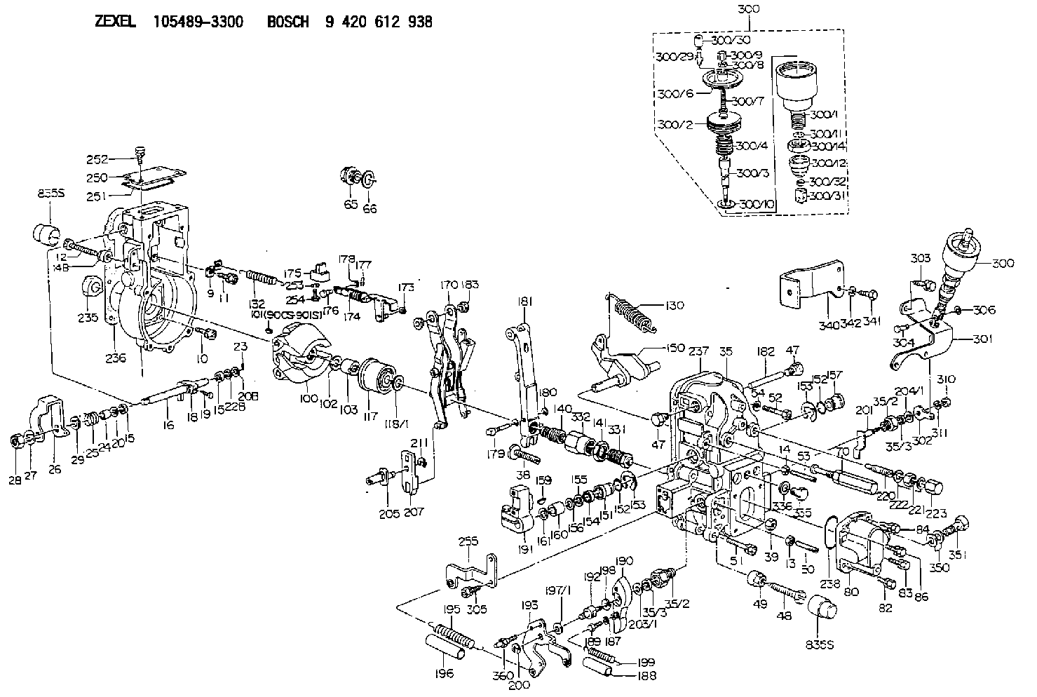
Information governor
BOSCH
9 420 612 938
9420612938
ZEXEL
105489-3300
1054893300
ISUZU
1157705690
1157705690

Rating:
Scheme ###:
| 1. | [1] | 154004-4621 | GOVERNOR HOUSING |
| 9. | [1] | 154353-5601 | PLATE |
| 10. | [4] | 020106-2040 | BLEEDER SCREW M6P1L20 |
| 11. | [4] | 020106-1840 | BLEEDER SCREW M6P1L18 |
| 12. | [1] | 154010-8100 | BLEEDER SCREW M8P1.25L65 |
| 13. | [1] | 013020-6040 | UNION NUT M6P1H5 |
| 14. | [1] | 154011-0100 | HEXAGON NUT |
| 14B. | [1] | 154011-2300 | UNION NUT |
| 15. | [2] | 139608-0100 | PACKING RING |
| 15. | [2] | 139608-0100 | PACKING RING |
| 16. | [1] | 155004-3600 | LEVER SHAFT |
| 18. | [1] | 155003-2101 | CONTROL LEVER |
| 19. | [1] | 155006-0700 | BLEEDER SCREW |
| 20. | [1] | 139308-0900 | PLAIN WASHER D16&8T1 |
| 20B. | [1] | 139308-1000 | PLAIN WASHER D16&8T1.5 |
| 22B. | [0] | 029310-8050 | SHIM D13.5&8T0.5 |
| 22B. | [7] | 139408-1500 | SHIM |
| 23. | [1] | 025520-1210 | SPLIT PIN |
| 24. | [1] | 154206-2000 | BUSHING |
| 25. | [1] | 154327-3600 | COILED SPRING |
| 26. | [1] | 154365-6500 | CONTROL LEVER |
| 27. | [1] | 014110-8440 | LOCKING WASHER |
| 28. | [1] | 013020-8040 | UNION NUT M8P1.25H7 |
| 29. | [1] | 139408-1400 | SHIM |
| 29B. | [0] | 139408-1400 | SHIM |
| 29C. | [0] | 139408-1500 | SHIM |
| 35. | [1] | 154515-7420 | GOVERNOR COVER |
| 35/2. | [2] | 154321-2000 | BUSHING |
| 35/2. | [2] | 154321-2000 | BUSHING |
| 35/3. | [2] | 139610-0600 | PACKING RING |
| 35/3. | [2] | 139610-0600 | PACKING RING |
| 38. | [1] | 154031-3401 | FLAT-HEAD SCREW |
| 39. | [1] | 029201-0160 | UNION NUT |
| 47. | [2] | 154036-1800 | CAPSULE |
| 47. | [2] | 154036-1800 | CAPSULE |
| 48. | [1] | 154010-5500 | BLEEDER SCREW M10P1.25L42 |
| 48B. | [1] | 154010-8200 | BLEEDER SCREW |
| 49. | [1] | 154011-2200 | UNION NUT |
| 50. | [1] | 155615-2300 | FLAT-HEAD SCREW |
| 51. | [5] | 020106-4540 | BLEEDER SCREW M6P1.0L45 |
| 52. | [2] | 029010-6850 | BLEEDER SCREW |
| 53. | [1] | 154010-0100 | FLAT-HEAD SCREW |
| 54. | [2] | 014110-6440 | LOCKING WASHER |
| 65. | [1] | 153021-5000 | CAP |
| 66. | [1] | 139524-0000 | GASKET |
| 70. | [1] | 154055-2420 | HEADLESS SCREW |
| 80. | [1] | 154063-7620 | COVER |
| 82. | [1] | 020006-1640 | BLEEDER SCREW M6P1L16 4T |
| 83. | [1] | 029020-6210 | BLEEDER SCREW |
| 84. | [1] | 020006-2040 | BLEEDER SCREW M6P1L20 4T |
| 86. | [1] | 029020-6260 | BLEEDER SCREW |
| 100. | [1] | 154100-9320 | FLYWEIGHT ASSEMBLY |
| 101. | [1] | 025803-1310 | WOODRUFF KEY |
| 102. | [1] | 029321-2020 | LOCKING WASHER |
| 103. | [1] | 139212-0000 | UNION NUT |
| 117. | [1] | 154123-2320 | SLIDING PIECE |
| 118/1. | [0] | 029311-0010 | SHIM D14&10.1T0.2 |
| 118/1. | [0] | 029311-0180 | SHIM D14&10.1T0.3 |
| 118/1. | [0] | 029311-0190 | SHIM D14&10.1T0.40 |
| 118/1. | [0] | 029311-0210 | SHIM D14&10.1T1 |
| 118/1. | [0] | 139410-0000 | SHIM D14.0&10.1T0.5 |
| 118/1. | [0] | 139410-0100 | SHIM D14.0&10.1T1.5 |
| 118/1. | [0] | 139410-3000 | SHIM D14&10.1T2.0 |
| 118/1. | [0] | 139410-3100 | SHIM D14&10.1T3.0 |
| 118/1. | [0] | 139410-3200 | SHIM D14&10.1T4.0 |
| 130. | [1] | 154150-8400 | GOVERNOR SPRING |
| 132. | [1] | 154154-0701 | COILED SPRING |
| 140. | [1] | 154183-1420 | HEADLESS SCREW |
| 141. | [1] | 139218-0100 | UNION NUT |
| 150. | [1] | 154200-5801 | SWIVELLING LEVER |
| 151. | [1] | 154200-5501 | BUSHING |
| 152. | [2] | 139719-0000 | O-RING |
| 152. | [2] | 139719-0000 | O-RING |
| 153. | [2] | 154354-3900 | LOCKING WASHER |
| 153. | [2] | 154354-3900 | LOCKING WASHER |
| 154. | [1] | 139612-0000 | PACKING RING |
| 155. | [1] | 139411-0100 | SHIM D22.0&12.0T0.40 |
| 156. | [0] | 139411-0200 | SHIM D18.0&12.0T0.10 |
| 156B. | [0] | 139411-0300 | SHIM D18.0&12.0T0.20 |
| 156C. | [0] | 139411-0400 | SHIM D18.0&12.0T0.30 |
| 157. | [1] | 154204-3500 | BUSHING |
| 159. | [1] | 025803-1310 | WOODRUFF KEY |
| 160. | [1] | 154206-2300 | BUSHING |
| 161. | [0] | 154206-2400 | PLAIN WASHER D20.5&12.2T1 |
| 170. | [1] | 154216-9121 | GUIDE LEVER |
| 173. | [1] | 016010-0540 | LOCKING WASHER |
| 174. | [1] | 154234-3220 | STRAP |
| 175. | [1] | 154232-1821 | CONNECTOR |
| 176. | [1] | 159231-4900 | BEARING PIN |
| 177. | [1] | 155402-3800 | SAFETY PIN |
| 178. | [1] | 029310-5170 | SHIM D8&5.3T0.5 |
| 179. | [1] | 154238-0201 | BEARING PIN |
| 180. | [1] | 016010-0540 | LOCKING WASHER |
| 181. | [1] | 154236-6320 | TENSIONING LEVER |
| 182. | [1] | 154237-1200 | BEARING PIN |
| 183. | [2] | 154237-1300 | BUSHING |
| 187. | [1] | 014110-6440 | LOCKING WASHER |
| 188. | [1] | 154156-1500 | TUBE |
| 189. | [1] | 154357-6320 | BLEEDER SCREW |
| 190. | [1] | 154360-2700 | CONTROL LEVER |
| 191. | [1] | 154340-1920 | CONTROL LEVER |
| 192. | [1] | 154372-2000 | BLEEDER SCREW |
| 193. | [1] | 154363-8320 | CONTROL LEVER |
| 195. | [1] | 154317-1000 | COILED SPRING |
| 196. | [1] | 154156-1300 | TUBE |
| 197/1. | [0] | 029310-8610 | SHIM D10.5&8.5T0.1 |
| 197/1. | [0] | 029310-8620 | SHIM D10.5&8.5T0.15 |
| 197/1. | [0] | 029310-8630 | SHIM D10.5&8.5T0.2 |
| 197/1. | [0] | 029310-8650 | SHIM D10.5&8.5T0.5 |
| 198. | [1] | 014110-8440 | LOCKING WASHER |
| 199. | [1] | 154317-2000 | COILED SPRING |
| 200. | [1] | 016010-0740 | LOCKING WASHER |
| 201. | [1] | 154324-4020 | LEVER SHAFT |
| 203/1. | [0] | 029311-0640 | SHIM D26.0&10.2T0.95 |
| 203/1. | [0] | 029311-0650 | SHIM D26.0&10.2T0.20 |
| 203/1. | [0] | 029311-0660 | SHIM D26.0&10.2T0.25 |
| 203/1. | [0] | 029311-0670 | SHIM D26.0&10.2T0.30 |
| 203/1. | [0] | 029311-0680 | SHIM D26.0&10.2T0.35 |
| 203/1. | [0] | 029311-0690 | SHIM D26.0&10.2T0.40 |
| 203/1. | [0] | 029311-0700 | SHIM D26.0&10.2T0.50 |
| 203/1. | [0] | 139410-1400 | SHIM D26&10.2T0.7 |
| 203/1. | [0] | 139410-1500 | SHIM D26&10.2T0.9 |
| 203/1. | [0] | 139410-1600 | SHIM D26&10.2T0.8 |
| 203/1. | [0] | 139410-2700 | SHIM D26&10.2T0.6 |
| 204/1. | [0] | 029311-0640 | SHIM D26.0&10.2T0.95 |
| 204/1. | [0] | 029311-0650 | SHIM D26.0&10.2T0.20 |
| 204/1. | [0] | 029311-0660 | SHIM D26.0&10.2T0.25 |
| 204/1. | [0] | 029311-0670 | SHIM D26.0&10.2T0.30 |
| 204/1. | [0] | 029311-0680 | SHIM D26.0&10.2T0.35 |
| 204/1. | [0] | 029311-0690 | SHIM D26.0&10.2T0.40 |
| 204/1. | [0] | 029311-0700 | SHIM D26.0&10.2T0.50 |
| 204/1. | [0] | 139410-1400 | SHIM D26&10.2T0.7 |
| 204/1. | [0] | 139410-1500 | SHIM D26&10.2T0.9 |
| 204/1. | [0] | 139410-1600 | SHIM D26&10.2T0.8 |
| 204/1. | [0] | 139410-2700 | SHIM D26&10.2T0.6 |
| 205. | [1] | 154324-3400 | LEVER SHAFT |
| 207. | [1] | 154326-0300 | CONTROL LEVER |
| 211. | [1] | 016010-0840 | LOCKING WASHER |
| 220. | [1] | 154050-6820 | HEADLESS SCREW |
| 221. | [1] | 029201-2130 | UNION NUT M12P1.0H6 |
| 222. | [2] | 139512-0000 | GASKET D17.2&12.2T1.0 |
| 223. | [1] | 154159-1200 | CAP NUT |
| 235. | [1] | 155412-5200 | IMPELLER WHEEL |
| 236. | [1] | 154371-5600 | GASKET |
| 237. | [1] | 154390-0200 | GASKET |
| 238. | [1] | 139756-0200 | O-RING |
| 250. | [1] | 154063-9800 | COVER |
| 251. | [1] | 154419-2500 | SEAL RING |
| 252. | [4] | 020106-1640 | BLEEDER SCREW M6P1.0L14 |
| 253. | [1] | 029320-5020 | LOCKING WASHER |
| 254. | [1] | 010535-1040 | FLAT-HEAD SCREW M5P0.8L10 |
| 255. | [1] | 154359-4820 | BRACKET |
| 300. | [1] | 155423-5820 | ANEROID CAPSULE |
| 300. | [1] | 155423-5820 | ANEROID CAPSULE |
| 300/1. | [1] | 155423-3720 | DIAPHRAGM HOUSING |
| 300/2. | [1] | 155403-3021 | BELLOWS |
| 300/3. | [1] | 155423-5920 | STOP PIN |
| 300/4. | [1] | 155423-4000 | COILED SPRING |
| 300/6. | [1] | 155423-2000 | COVER |
| 300/7. | [1] | 155423-1500 | SCREW PLUG |
| 300/8. | [1] | 029240-6010 | UNION NUT M6P1.0H5* |
| 300/9. | [1] | 154035-1600 | CAP NUT |
| 300/10. | [1] | 029311-2060 | SHIM D22&12.5T0.5 |
| 300/11. | [1] | 016020-1220 | LOCKING WASHER |
| 300/12. | [1] | 155403-2200 | COVER |
| 300/14. | [1] | 139222-0000 | UNION NUT |
| 300/29. | [1] | 139805-0000 | JOINT CONNECTION |
| 300/30. | [1] | 155424-0300 | CAP |
| 300/31. | [1] | 155423-6000 | CLEVIS |
| 300/32. | [1] | 029200-5130 | UNION NUT |
| 301. | [1] | 154358-3921 | CONTROL LEVER |
| 302. | [1] | 154363-4300 | CONTROL LEVER |
| 302B. | [1] | 154363-4400 | CONTROL LEVER |
| 303. | [1] | 020018-1640 | BLEEDER SCREW M8P1.25L16 4T |
| 304. | [1] | 154222-7800 | BEARING PIN |
| 305. | [2] | 020118-1240 | BLEEDER SCREW M8P1.25L12 |
| 306. | [1] | 016010-0540 | LOCKING WASHER |
| 310. | [1] | 013020-6040 | UNION NUT M6P1H5 |
| 311. | [1] | 014110-6440 | LOCKING WASHER |
| 331. | [1] | 154179-4120 | HEADLESS SCREW |
| 332. | [1] | 139218-0500 | UNION NUT |
| 335. | [1] | 154352-2600 | CAPSULE |
| 336. | [1] | 139516-0100 | GASKET |
| 340. | [1] | 154357-6621 | BRACKET |
| 341. | [2] | 010038-1440 | BLEEDER SCREW M8P1.25L14 |
| 342. | [2] | 014110-8440 | LOCKING WASHER |
| 350. | [2] | 139512-0000 | GASKET D17.2&12.2T1.0 |
| 351. | [1] | 139812-0100 | EYE BOLT |
| 360. | [1] | 154357-7000 | BEARING PIN |
| 900S. | [1] | 025803-1310 | WOODRUFF KEY |
| 901S. | [1] | 025803-1610 | WOODRUFF KEY |
Cross reference number
Zexel num
Bosch num
Firm num
Name
Information:
1. Remove four bolts and shield (1). Remove two bolts and screen (2). Disconnect ground strap (3) from the generator mounting bracket. Remove two generator mounting bolts (4). 2. Loosen front engine mounting bolts (5) to provide clearance to raise the rear of the engine. 3. Attach a hoist to generator (6). Raise the generator and the engine so the generator mounting pads are off of the supports. Put blocks under the flywheel housing to support the rear of the engine as shown. 4. Remove bolts (7) that hold fan (9) to the flywheel. Remove bolts (8) that hold the generator housing to the flywheel housing and remove the generator. The weight of the generator is approximately 1130 kg (2500 lb.).Connection Of Engine And Generator (Prime)
The following procudure applies to the 3406B Standby Generator also. 1. Remove the protection material (compound) from the flywheel pilot bore (10) and from the surface (11) that makes contact with the coupling. All contact surfaces of the engine, coupling and generator must be completely clean. 2. Install tooling (A) as shown on the front of the engine with the tip of the indicator on the face of crankshaft pulley (12). Use a bar between the flywheel and flywheel housing to push the crankshaft toward the flywheel to remove all end play. Put the dial indicator in the "zero" position. Move the crankshaft to its most forward position, and make a record of the Total Indicator Reading (TIR). The TIR is the end play of the crankshaft. 3. Put plate assembly (13) in position in the bore of the flywheel to check for clearance. There must be clearance between the outside diameter of the plate assembly (13) and the inside diameter of the bore in the flywheel.
Damage to the engine and/or generator can be the result if the electric set is run with a plate assembly that does not have this clearance.
4. Install full shim pack (14) and plate assembly (13) on the generator with bolts (15).5. Install a guide bolt in the flywheel. Put the generator in position on the engine, and install bolts (7) and (8).6. Use tooling (A) to check crankshaft end play. Do not use force to hold the crankshaft in position. Remove the generator. Remove only enough shims to get the original amount of end play as shown in Step 2. The minimum crankshaft end play should be 0.15 mm (0.006 in.).7. Install the generator and check the crankshaft end play again. If the end play is correct, attach a hoist to the generator and remove the blocks from under the flywheel housing.8. Lower the generator on to the supports and install bolts (4). Connect ground strap (3) to the generator. Install screen (2) and shield (1).9. Tighten fron engine mounting bolts (5).End By:a. install control panel enclosure