Information governor
BOSCH
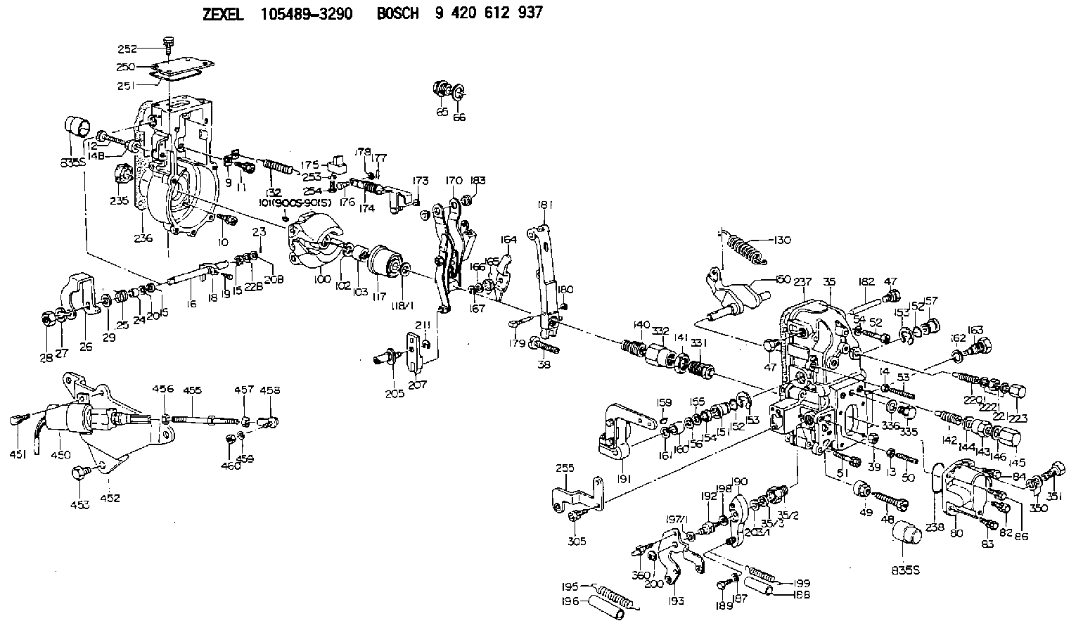
9 420 612 937
9420612937
ZEXEL
105489-3290
1054893290
Rating:
Scheme ###:
| 1. | [1] | 154004-4621 | GOVERNOR HOUSING |
| 9. | [1] | 154350-6000 | PLATE |
| 10. | [4] | 139006-4100 | BLEEDER SCREW |
| 11. | [4] | 139006-5800 | BLEEDER SCREW |
| 12. | [1] | 154010-8100 | BLEEDER SCREW M8P1.25L65 |
| 13. | [1] | 013020-6040 | UNION NUT M6P1H5 |
| 14. | [1] | 154011-0100 | HEXAGON NUT |
| 14B. | [1] | 154011-2300 | UNION NUT |
| 15. | [2] | 139608-0100 | PACKING RING |
| 15. | [2] | 139608-0100 | PACKING RING |
| 16. | [1] | 155004-3600 | LEVER SHAFT |
| 18. | [1] | 155003-2101 | CONTROL LEVER |
| 19. | [1] | 155006-0700 | BLEEDER SCREW |
| 20. | [1] | 139308-0900 | PLAIN WASHER D16&8T1 |
| 20B. | [1] | 139308-1000 | PLAIN WASHER D16&8T1.5 |
| 22B. | [0] | 029310-8050 | SHIM D13.5&8T0.5 |
| 22B. | [7] | 139408-1500 | SHIM |
| 23. | [1] | 025520-1210 | SPLIT PIN |
| 24. | [1] | 154206-2000 | BUSHING |
| 25. | [1] | 154327-3600 | COILED SPRING |
| 26. | [1] | 154380-9900 | CONTROL LEVER |
| 27. | [1] | 014110-8440 | LOCKING WASHER |
| 28. | [1] | 013020-8040 | UNION NUT M8P1.25H7 |
| 29. | [1] | 139408-1400 | SHIM |
| 29B. | [0] | 139408-1400 | SHIM |
| 29C. | [0] | 139408-1500 | SHIM |
| 35. | [1] | 154515-0620 | GOVERNOR COVER |
| 35/2. | [1] | 154321-2000 | BUSHING |
| 35/3. | [1] | 139610-0600 | PACKING RING |
| 38. | [1] | 154031-3401 | FLAT-HEAD SCREW |
| 39. | [1] | 029201-0160 | UNION NUT |
| 47. | [2] | 154036-1800 | CAPSULE |
| 47. | [2] | 154036-1800 | CAPSULE |
| 48. | [1] | 154010-6000 | BLEEDER SCREW M10P1.25L55 |
| 48B. | [1] | 154010-7700 | BLEEDER SCREW M10P1.25L51 |
| 49. | [1] | 154011-2200 | UNION NUT |
| 50. | [1] | 155615-2300 | FLAT-HEAD SCREW |
| 51. | [5] | 020106-4540 | BLEEDER SCREW M6P1.0L45 |
| 52. | [2] | 029010-6850 | BLEEDER SCREW |
| 53. | [1] | 154010-0100 | FLAT-HEAD SCREW |
| 54. | [2] | 014110-6440 | LOCKING WASHER |
| 65. | [1] | 153021-5000 | CAP |
| 66. | [1] | 139524-0000 | GASKET |
| 80. | [1] | 154063-5620 | COVER |
| 82. | [1] | 020006-1640 | BLEEDER SCREW M6P1L16 4T |
| 83. | [1] | 029020-6210 | BLEEDER SCREW |
| 84. | [1] | 020006-1640 | BLEEDER SCREW M6P1L16 4T |
| 86. | [1] | 029020-6210 | BLEEDER SCREW |
| 100. | [1] | 154100-9220 | FLYWEIGHT ASSEMBLY |
| 101. | [1] | 025803-1310 | WOODRUFF KEY |
| 102. | [1] | 029321-2020 | LOCKING WASHER |
| 103. | [1] | 139212-0000 | UNION NUT |
| 117. | [1] | 154123-2320 | SLIDING PIECE |
| 118/1. | [0] | 029311-0010 | SHIM D14&10.1T0.2 |
| 118/1. | [0] | 029311-0180 | SHIM D14&10.1T0.3 |
| 118/1. | [0] | 029311-0190 | SHIM D14&10.1T0.40 |
| 118/1. | [0] | 029311-0210 | SHIM D14&10.1T1 |
| 118/1. | [0] | 139410-0000 | SHIM D14.0&10.1T0.5 |
| 118/1. | [0] | 139410-0100 | SHIM D14.0&10.1T1.5 |
| 118/1. | [0] | 139410-3000 | SHIM D14&10.1T2.0 |
| 118/1. | [0] | 139410-3100 | SHIM D14&10.1T3.0 |
| 118/1. | [0] | 139410-3200 | SHIM D14&10.1T4.0 |
| 130. | [1] | 154150-9000 | GOVERNOR SPRING |
| 132. | [1] | 154154-3700 | COILED SPRING |
| 140. | [1] | 154183-8020 | HEADLESS SCREW |
| 141. | [1] | 139218-0100 | UNION NUT |
| 142. | [1] | 154242-3320 | HEADLESS SCREW |
| 143. | [1] | 154242-3200 | UNION NUT |
| 144. | [1] | 139516-0100 | GASKET |
| 145. | [1] | 154159-1800 | CAP NUT |
| 146. | [1] | 139516-0100 | GASKET |
| 150. | [1] | 154200-5801 | SWIVELLING LEVER |
| 151. | [1] | 154200-5501 | BUSHING |
| 152. | [2] | 139719-0000 | O-RING |
| 152. | [2] | 139719-0000 | O-RING |
| 153. | [2] | 154354-3900 | LOCKING WASHER |
| 153. | [2] | 154354-3900 | LOCKING WASHER |
| 154. | [1] | 139612-0000 | PACKING RING |
| 155. | [1] | 139411-0100 | SHIM D22.0&12.0T0.40 |
| 156. | [0] | 139411-0200 | SHIM D18.0&12.0T0.10 |
| 156B. | [0] | 139411-0300 | SHIM D18.0&12.0T0.20 |
| 156C. | [0] | 139411-0400 | SHIM D18.0&12.0T0.30 |
| 157. | [1] | 154204-3500 | BUSHING |
| 159. | [1] | 025803-1310 | WOODRUFF KEY |
| 160. | [1] | 154206-2300 | BUSHING |
| 161. | [0] | 154206-2400 | PLAIN WASHER D20.5&12.2T1 |
| 162. | [1] | 139516-0100 | GASKET |
| 163. | [1] | 154401-3201 | BLEEDER SCREW |
| 164. | [1] | 154243-0820 | CONTROL LEVER |
| 165. | [1] | 154327-6100 | COILED SPRING |
| 166. | [1] | 029310-8320 | SHIM D16.5&8T0.2 |
| 167. | [1] | 154356-3600 | LOCKING WASHER |
| 170. | [1] | 154216-7020 | FORK LEVER |
| 173. | [1] | 016010-0540 | LOCKING WASHER |
| 174. | [1] | 154235-0820 | STRAP |
| 175. | [1] | 154232-1821 | CONNECTOR |
| 176. | [1] | 159231-4900 | BEARING PIN |
| 177. | [1] | 155402-3800 | SAFETY PIN |
| 178. | [1] | 029310-5170 | SHIM D8&5.3T0.5 |
| 179. | [1] | 154238-0201 | BEARING PIN |
| 180. | [1] | 016010-0540 | LOCKING WASHER |
| 181. | [1] | 154236-9721 | TENSIONING LEVER |
| 182. | [1] | 154237-1200 | BEARING PIN |
| 183. | [2] | 154237-1300 | BUSHING |
| 187. | [1] | 014110-6440 | LOCKING WASHER |
| 188. | [1] | 154156-1500 | TUBE |
| 189. | [1] | 154357-6320 | BLEEDER SCREW |
| 190. | [1] | 154360-2700 | CONTROL LEVER |
| 191. | [1] | 154349-7520 | CONTROL LEVER |
| 192. | [1] | 154371-8300 | BLEEDER SCREW |
| 193. | [1] | 154363-8320 | CONTROL LEVER |
| 195. | [1] | 154317-1000 | COILED SPRING |
| 196. | [1] | 154156-1300 | TUBE |
| 197/1. | [0] | 029310-8610 | SHIM D10.5&8.5T0.1 |
| 197/1. | [0] | 029310-8620 | SHIM D10.5&8.5T0.15 |
| 197/1. | [0] | 029310-8630 | SHIM D10.5&8.5T0.2 |
| 197/1. | [0] | 029310-8650 | SHIM D10.5&8.5T0.5 |
| 198. | [1] | 014110-8440 | LOCKING WASHER |
| 199. | [1] | 154317-2000 | COILED SPRING |
| 200. | [1] | 016010-0740 | LOCKING WASHER |
| 203/1. | [0] | 029311-0640 | SHIM D26.0&10.2T0.95 |
| 203/1. | [0] | 029311-0650 | SHIM D26.0&10.2T0.20 |
| 203/1. | [0] | 029311-0660 | SHIM D26.0&10.2T0.25 |
| 203/1. | [0] | 029311-0670 | SHIM D26.0&10.2T0.30 |
| 203/1. | [0] | 029311-0680 | SHIM D26.0&10.2T0.35 |
| 203/1. | [0] | 029311-0690 | SHIM D26.0&10.2T0.40 |
| 203/1. | [0] | 029311-0700 | SHIM D26.0&10.2T0.50 |
| 203/1. | [0] | 139410-1400 | SHIM D26&10.2T0.7 |
| 203/1. | [0] | 139410-1500 | SHIM D26&10.2T0.9 |
| 203/1. | [0] | 139410-1600 | SHIM D26&10.2T0.8 |
| 203/1. | [0] | 139410-2700 | SHIM D26&10.2T0.6 |
| 205. | [1] | 154324-4100 | LEVER SHAFT |
| 207. | [1] | 154326-0300 | CONTROL LEVER |
| 211. | [1] | 016010-0840 | LOCKING WASHER |
| 220. | [1] | 154050-7720 | HEADLESS SCREW |
| 221. | [1] | 029201-2130 | UNION NUT M12P1.0H6 |
| 222. | [2] | 139512-0000 | GASKET D17.2&12.2T1.0 |
| 223. | [1] | 154159-1200 | CAP NUT |
| 235. | [1] | 155412-5200 | IMPELLER WHEEL |
| 236. | [1] | 154371-5600 | GASKET |
| 237. | [1] | 154390-0200 | GASKET |
| 238. | [1] | 139756-0200 | O-RING |
| 250. | [1] | 154063-9800 | COVER |
| 251. | [1] | 154419-2500 | SEAL RING |
| 252. | [4] | 020106-1640 | BLEEDER SCREW M6P1.0L14 |
| 253. | [1] | 029320-5020 | LOCKING WASHER |
| 254. | [1] | 010535-1040 | FLAT-HEAD SCREW M5P0.8L10 |
| 255. | [1] | 154359-4820 | BRACKET |
| 305. | [2] | 020118-1240 | BLEEDER SCREW M8P1.25L12 |
| 331. | [1] | 154188-0320 | HEADLESS SCREW |
| 332. | [1] | 139218-0500 | UNION NUT |
| 335. | [1] | 154352-2600 | CAPSULE |
| 336. | [1] | 139516-0100 | GASKET |
| 350. | [2] | 139512-0000 | GASKET D17.2&12.2T1.0 |
| 351. | [1] | 139812-0100 | EYE BOLT |
| 360. | [1] | 154357-7000 | BEARING PIN |
| 450. | [1] | 154410-4300 | SOLENOID |
| 451. | [2] | 020106-1040 | BLEEDER SCREW M6P1L12 |
| 452. | [1] | 154373-6200 | BRACKET |
| 453. | [3] | 139016-0700 | BLEEDER SCREW |
| 455. | [1] | 154373-6300 | LEVER SHAFT |
| 456. | [1] | 013020-6040 | UNION NUT M6P1H5 |
| 457. | [1] | 029200-5130 | UNION NUT |
| 458. | [1] | 159227-4100 | JOINT CONNECTION |
| 459. | [1] | 014110-5440 | LOCKING WASHER |
| 460. | [1] | 013010-5240 | UNION NUT M5P0.8H4 |
| 900S. | [1] | 025803-1310 | WOODRUFF KEY |
| 901S. | [1] | 025803-1610 | WOODRUFF KEY |
Include in #1:
106991-1270
as GOVERNOR
Cross reference number
Zexel num
Bosch num
Firm num
Name
Information:
1. Disconnect the batteries. 2. Remove top panel (1), front panel (2) and the rear panel from the enclosure. 3. Remove the bolt holding ground wires (5) to the frame. Remove wire ties (4) to separate the ground wires. Remove two screws and cover (3). 4. Remove three bolts (7) to disconnect the power bars from the main circuit breaker. Remove the insulation material from power bar (6). Remove bolts (8) holding ground bar (9) to the panel. Put identification on the wires for assembly purposes.5. Disconnect wires (10) from the terminal strip. Disconnect wires (11) from the voltage regulator. 6. Disconnect wires (12) from the inside of the control panel. 7. Remove bolts (13) and disconnect the small gage wire from each power bar. 8. Disconnect wire loom (14) from the generator housing and from the inside of the enclosure at three places. Remove the bolts and lower panel (15). Be sure all wires are free from the enclosure 9. Attach tooling (A) and a hoist to the enclosure as shown. Remove four bolts that fasten the enclosure to the base. Remove the enclosure. The weight of the enclosure is 1258 kg (570 lb.). The following steps are for the installation of the control panel enclosure.10. Use a hoist and tooling (A) to put the enclosure in position on the base. Install the four bolts that hold it to the base.11. Connect wire loom (14) to the generator housing and to the inside of the enclosure at three places. Install lower panel (15).12. Connect small gage wire to each power bar with bolts (13).13. Connect wires (12) to the inside of the control panel.14. Connect wires (10) to the terminal strip. Connect wires (11) to the voltage regulator.15. Connect ground bar (9) to the panel with two bolts (8). Wrap insulation material around power bar (6). Connect the power bars to the main circuit breaker with three bolts (7).16. Connect ground wires (5) to the frame and install wire ties (4) to hold the wires together. Install cover (3) with two screws.17. Install the rear, front and top panels on the enclosure.18. Connect the batteries.Remove Control Panel Enclosure (Standby)
The photographs shown are of a 3306B Standby Generator. The procedure is the same for the 3406B Standby Generator. 1. Remove door (1).2. Remove two bolts (2) from cover (3). 3. Remove doors (4).4. Remove fourteen bolts (7) and cover (5).5. Remove the battery charger. See the topic, Remove And Install Battery Charger.6. Remove the bolts and cover (6).7. Remove the three bolts located above the control panel and remove cover (3). 8. Identify and disconnect all the wires from breaker (9) and grounding buss (10).9. Remove bolts (8), bracket (11), and breaker (9). 10. Identify and disconnect all wires (12) between the generator and the control panels from the terminal strips on the control panels.11. Identify and disconnect all wires between the engine and control panels from the terminal strips on the control panels.12. Remove bolts (13). 13.
The photographs shown are of a 3306B Standby Generator. The procedure is the same for the 3406B Standby Generator. 1. Remove door (1).2. Remove two bolts (2) from cover (3). 3. Remove doors (4).4. Remove fourteen bolts (7) and cover (5).5. Remove the battery charger. See the topic, Remove And Install Battery Charger.6. Remove the bolts and cover (6).7. Remove the three bolts located above the control panel and remove cover (3). 8. Identify and disconnect all the wires from breaker (9) and grounding buss (10).9. Remove bolts (8), bracket (11), and breaker (9). 10. Identify and disconnect all wires (12) between the generator and the control panels from the terminal strips on the control panels.11. Identify and disconnect all wires between the engine and control panels from the terminal strips on the control panels.12. Remove bolts (13). 13.