Information governor
BOSCH
9 420 612 254
9420612254
ZEXEL
105489-3190
1054893190
MITSUBISHI
ME730248
me730248
Rating:
Scheme ###:
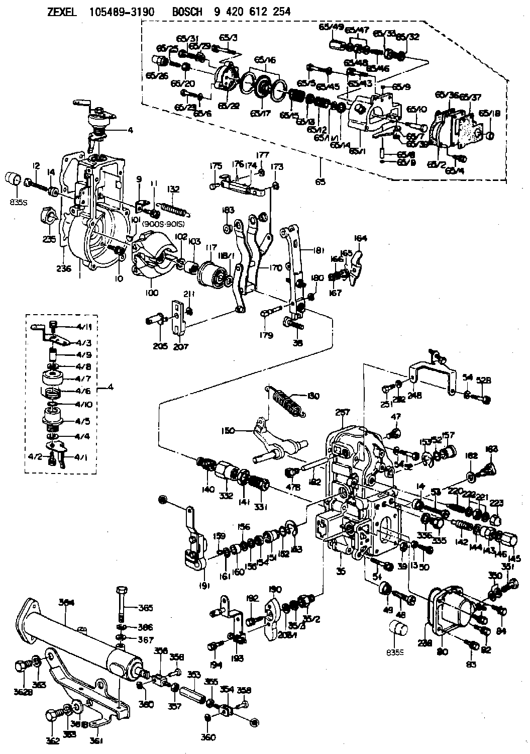
| 1. | [1] | 154004-0100 | GOVERNOR HOUSING |
| 4. | [1] | 154365-2120 | CONTROL LEVER |
| 4. | [1] | 154365-2120 | CONTROL LEVER |
| 4/1. | [1] | 154304-6200 | CONTROL LEVER |
| 4/2. | [1] | 154352-2000 | BLEEDER SCREW |
| 4/3. | [1] | 154365-2100 | CONTROL LEVER |
| 4/4. | [1] | 029311-0230 | SHIM D18&10.3T0.5 |
| 4/5. | [1] | 154321-1500 | BUSHING |
| 4/6. | [1] | 154327-6600 | COILED SPRING |
| 4/7. | [1] | 154322-0100 | CAP |
| 4/8. | [1] | 029311-0220 | SHIM D18&10.3T0.2 |
| 4/9. | [1] | 154324-2700 | LEVER SHAFT |
| 4/10. | [1] | 029631-0030 | O-RING &9.8W2.3 |
| 4/11. | [1] | 020006-1240 | BLEEDER SCREW M6P1L12 4T |
| 9. | [1] | 154350-6000 | PLATE |
| 10. | [4] | 020106-2040 | BLEEDER SCREW M6P1L20 |
| 11. | [4] | 020106-1840 | BLEEDER SCREW M6P1L18 |
| 12. | [1] | 154013-0600 | BLEEDER SCREW |
| 13. | [1] | 013020-6040 | UNION NUT M6P1H5 |
| 14. | [2] | 154011-2300 | UNION NUT |
| 14. | [2] | 154011-2300 | UNION NUT |
| 35. | [1] | 154515-4820 | GOVERNOR COVER |
| 35/2. | [1] | 154321-2000 | BUSHING |
| 35/3. | [1] | 029621-0080 | PACKING RING |
| 38. | [1] | 154031-3401 | FLAT-HEAD SCREW |
| 39. | [1] | 029201-0160 | UNION NUT |
| 47. | [1] | 154036-1900 | CAPSULE |
| 47B. | [1] | 154036-1800 | CAPSULE |
| 48. | [1] | 154010-7700 | BLEEDER SCREW M10P1.25L51 |
| 48B. | [1] | 154010-7100 | BLEEDER SCREW M10P1.25L47 |
| 49. | [1] | 154011-2200 | UNION NUT |
| 50. | [1] | 155615-1900 | BLEEDER SCREW |
| 51. | [5] | 020106-4540 | BLEEDER SCREW M6P1.0L45 |
| 52. | [1] | 010006-6040 | BLEEDER SCREW |
| 52B. | [1] | 029010-6850 | BLEEDER SCREW |
| 53. | [1] | 154010-7200 | BLEEDER SCREW M8P1.25L62 |
| 53B. | [1] | 154010-8100 | BLEEDER SCREW M8P1.25L65 |
| 54. | [2] | 014110-6440 | LOCKING WASHER |
| 54. | [2] | 014110-6440 | LOCKING WASHER |
| 65. | [1] | 154419-6420 | MANIFOLD-PRESSURE COMP. |
| 65/1. | [1] | 154408-6621 | DIAPHRAGM HOUSING |
| 65/1B. | [1] | 134009-0000 | SPACER BUSHING |
| 65/2. | [1] | 154408-2400 | SPACER BUSHING |
| 65/3. | [2] | 020106-2240 | BLEEDER SCREW |
| 65/4. | [2] | 020106-1640 | BLEEDER SCREW M6P1.0L14 |
| 65/5. | [1] | 029010-6830 | BLEEDER SCREW |
| 65/6. | [1] | 014110-6440 | LOCKING WASHER |
| 65/7. | [1] | 154408-6700 | CONTROL LEVER |
| 65/8. | [1] | 154406-5000 | BEARING PIN |
| 65/9. | [2] | 154406-5100 | CAPSULE |
| 65/9. | [2] | 154406-5100 | CAPSULE |
| 65/10. | [1] | 154400-5700 | STOP PIN |
| 65/11/1. | [0] | 029311-2190 | SHIM D17.7&12T1.0 |
| 65/11/1. | [0] | 029311-2200 | SHIM D17.7&12T1.1 |
| 65/11/1. | [0] | 029311-2210 | SHIM D17.7&12T1.2 |
| 65/11/1. | [0] | 029311-2220 | SHIM D17.7&12T1.3 |
| 65/11/1. | [0] | 029311-2230 | SHIM D17.7&12T1.4 |
| 65/12. | [1] | 154411-1000 | COILED SPRING |
| 65/13. | [1] | 154406-5200 | SLOTTED WASHER |
| 65/14. | [0] | 029312-0180 | SHIM D25.5&20T0.5 |
| 65/14B. | [0] | 029312-0210 | SHIM D25.5&20T0.2 |
| 65/15. | [1] | 154411-2900 | COILED SPRING |
| 65/16. | [2] | 154413-2600 | GASKET |
| 65/17. | [1] | 154400-7720 | DIAPHRAGM |
| 65/20. | [1] | 023040-6040 | UNION NUT |
| 65/22. | [1] | 154404-5000 | COVER |
| 65/23. | [1] | 139006-0900 | BLEEDER SCREW |
| 65/25. | [1] | 154404-1600 | FLAT-HEAD SCREW L26.00 |
| 65/26. | [1] | 154406-7800 | CAP NUT |
| 65/29. | [2] | 026510-1340 | GASKET D13.4&10.2T1 |
| 65/31. | [1] | 029731-0180 | EYE BOLT |
| 65/32. | [1] | 026510-1340 | GASKET D13.4&10.2T1 |
| 65/33. | [1] | 154036-1600 | ADAPTOR |
| 65/36. | [1] | 154390-0800 | GASKET |
| 65/37. | [1] | 154390-0900 | GASKET |
| 65/39. | [1] | 029310-5160 | SHIM D11.5&5.2T0.50 |
| 65/43. | [2] | 020106-2540 | BLEEDER SCREW M6P1L25 |
| 65/45. | [1] | 014110-6440 | LOCKING WASHER |
| 65/46. | [1] | 154034-1600 | FLAT-HEAD SCREW L30 |
| 65/47. | [2] | 026506-1040 | GASKET D9.9&6.2T1 |
| 65/48. | [1] | 029240-6010 | UNION NUT M6P1.0H5* |
| 65/49. | [1] | 154035-1900 | CAP NUT |
| 80. | [1] | 154063-6521 | COVER |
| 82. | [1] | 020006-1640 | BLEEDER SCREW M6P1L16 4T |
| 83. | [1] | 029020-6210 | BLEEDER SCREW |
| 84. | [1] | 020006-1640 | BLEEDER SCREW M6P1L16 4T |
| 86. | [1] | 029020-6210 | BLEEDER SCREW |
| 100. | [1] | 154100-9220 | FLYWEIGHT ASSEMBLY |
| 101. | [1] | 025803-1310 | WOODRUFF KEY |
| 102. | [1] | 029321-2020 | LOCKING WASHER |
| 103. | [1] | 139212-0000 | UNION NUT |
| 117. | [1] | 154123-2320 | SLIDING PIECE |
| 118/1. | [0] | 029311-0010 | SHIM D14&10.1T0.2 |
| 118/1. | [0] | 029311-0180 | SHIM D14&10.1T0.3 |
| 118/1. | [0] | 029311-0190 | SHIM D14&10.1T0.40 |
| 118/1. | [0] | 029311-0210 | SHIM D14&10.1T1 |
| 118/1. | [0] | 139410-0000 | SHIM D14.0&10.1T0.5 |
| 118/1. | [0] | 139410-0100 | SHIM D14.0&10.1T1.5 |
| 118/1. | [0] | 139410-3000 | SHIM D14&10.1T2.0 |
| 118/1. | [0] | 139410-3100 | SHIM D14&10.1T3.0 |
| 118/1. | [0] | 139410-3200 | SHIM D14&10.1T4.0 |
| 130. | [1] | 154150-7900 | GOVERNOR SPRING |
| 132. | [1] | 154154-0701 | COILED SPRING |
| 140. | [1] | 154183-7820 | HEADLESS SCREW |
| 141. | [1] | 139218-0100 | UNION NUT |
| 142. | [1] | 154242-5120 | HEADLESS SCREW |
| 143. | [1] | 154242-3200 | UNION NUT |
| 144. | [1] | 026516-2040 | GASKET D19.9&16.2T1 |
| 145. | [1] | 154159-1800 | CAP NUT |
| 146. | [1] | 029331-6130 | GASKET |
| 150. | [1] | 154200-5601 | SWIVELLING LEVER |
| 151. | [1] | 154200-5501 | BUSHING |
| 152. | [2] | 139700-0000 | O-RING |
| 152. | [2] | 139700-0000 | O-RING |
| 153. | [2] | 154354-3900 | LOCKING WASHER |
| 153. | [2] | 154354-3900 | LOCKING WASHER |
| 154. | [1] | 139610-0101 | PACKING RING |
| 155. | [1] | 139411-0100 | SHIM D22.0&12.0T0.40 |
| 156. | [0] | 139411-0200 | SHIM D18.0&12.0T0.10 |
| 156B. | [0] | 139411-0300 | SHIM D18.0&12.0T0.20 |
| 156C. | [0] | 139411-0400 | SHIM D18.0&12.0T0.30 |
| 157. | [1] | 154204-3500 | BUSHING |
| 159. | [1] | 025803-1310 | WOODRUFF KEY |
| 160. | [1] | 154206-2300 | BUSHING |
| 161. | [0] | 154206-2400 | PLAIN WASHER D20.5&12.2T1 |
| 162. | [1] | 029331-6050 | GASKET |
| 163. | [1] | 154401-3201 | BLEEDER SCREW |
| 164. | [1] | 154243-0820 | CONTROL LEVER |
| 165. | [1] | 154327-6100 | COILED SPRING |
| 166. | [1] | 029310-8320 | SHIM D16.5&8T0.2 |
| 167. | [1] | 154356-3600 | LOCKING WASHER |
| 170. | [1] | 154216-7020 | FORK LEVER |
| 173. | [1] | 016010-0540 | LOCKING WASHER |
| 174. | [1] | 154235-0920 | STRAP |
| 175. | [1] | 159231-4900 | BEARING PIN |
| 176. | [1] | 155402-3800 | SAFETY PIN |
| 177. | [1] | 029310-5170 | SHIM D8&5.3T0.5 |
| 179. | [1] | 154238-0201 | BEARING PIN |
| 180. | [1] | 016010-0540 | LOCKING WASHER |
| 181. | [1] | 154236-9721 | TENSIONING LEVER |
| 182. | [1] | 154237-1200 | BEARING PIN |
| 183. | [2] | 154237-1300 | BUSHING |
| 190. | [1] | 154360-2700 | CONTROL LEVER |
| 191. | [1] | 154349-4920 | CONTROL LEVER |
| 192. | [1] | 020006-1670 | BLEEDER SCREW M6P1L16 7T |
| 193. | [1] | 154368-4920 | CONTROL LEVER |
| 194. | [2] | 020006-1240 | BLEEDER SCREW M6P1L12 4T |
| 203/1. | [0] | 029311-0640 | SHIM D26.0&10.2T0.95 |
| 203/1. | [0] | 029311-0650 | SHIM D26.0&10.2T0.20 |
| 203/1. | [0] | 029311-0660 | SHIM D26.0&10.2T0.25 |
| 203/1. | [0] | 029311-0670 | SHIM D26.0&10.2T0.30 |
| 203/1. | [0] | 029311-0680 | SHIM D26.0&10.2T0.35 |
| 203/1. | [0] | 029311-0690 | SHIM D26.0&10.2T0.40 |
| 203/1. | [0] | 029311-0700 | SHIM D26.0&10.2T0.50 |
| 203/1. | [0] | 139410-1400 | SHIM D26&10.2T0.7 |
| 203/1. | [0] | 139410-1500 | SHIM D26&10.2T0.9 |
| 203/1. | [0] | 139410-1600 | SHIM D26&10.2T0.8 |
| 203/1. | [0] | 139410-2700 | SHIM D26&10.2T0.6 |
| 205. | [1] | 154324-2900 | LEVER SHAFT |
| 207. | [1] | 154326-0300 | CONTROL LEVER |
| 211. | [1] | 016010-0840 | LOCKING WASHER |
| 220. | [1] | 154050-6820 | HEADLESS SCREW |
| 221. | [1] | 029201-2130 | UNION NUT M12P1.0H6 |
| 222. | [2] | 026512-1540 | GASKET D15.4&12.2T1.50 |
| 223. | [1] | 154159-0100 | CAP NUT |
| 235. | [1] | 155412-5200 | IMPELLER WHEEL |
| 236. | [1] | 154371-5600 | GASKET |
| 237. | [1] | 154390-0200 | GASKET |
| 238. | [1] | 139700-0100 | O-RING |
| 248. | [1] | 154357-9720 | BRACKET |
| 251. | [1] | 010065-1240 | BLEEDER SCREW M5P0.8L12 |
| 252. | [1] | 014110-5440 | LOCKING WASHER |
| 331. | [1] | 154179-4120 | HEADLESS SCREW |
| 332. | [1] | 139218-0500 | UNION NUT |
| 335. | [1] | 154352-2600 | CAPSULE |
| 336. | [1] | 029331-6030 | GASKET |
| 350. | [2] | 026512-1840 | GASKET D17.9&12.2T1.50 |
| 351. | [1] | 153556-4800 | EYE BOLT |
| 353. | [1] | 154354-3800 | UNION NUT M6P1H30 |
| 353. | [1] | 154354-3800 | UNION NUT M6P1H30 |
| 353B. | [1] | 154351-9200 | UNION NUT M6P1H40 |
| 354. | [1] | 154352-4300 | CLEVIS |
| 355. | [1] | 013020-6040 | UNION NUT M6P1H5 |
| 356. | [1] | 154351-9400 | CLEVIS |
| 357. | [1] | 029200-6210 | UNION NUT |
| 358. | [2] | 154604-2400 | BEARING PIN |
| 358. | [2] | 154604-2400 | BEARING PIN |
| 360. | [2] | 016010-0640 | LOCKING WASHER |
| 360. | [2] | 016010-0640 | LOCKING WASHER |
| 361. | [1] | 154372-7520 | BRACKET |
| 361B. | [1] | 139316-0100 | PLAIN WASHER |
| 362. | [2] | 139016-0400 | BLEEDER SCREW |
| 362B. | [1] | 029001-6050 | BLEEDER SCREW |
| 363. | [3] | 014111-6440 | LOCKING WASHER |
| 364. | [1] | 154354-6120 | CONTROL CYLINDER |
| 365. | [2] | 010110-7540 | BLEEDER SCREW |
| 366. | [2] | 014111-0440 | LOCKING WASHER |
| 367. | [2] | 014011-0140 | PLAIN WASHER D22&10.5T1.6 |
| 835S. | [3] | 154062-1700 | CAP D20L32 |
| 835S. | [3] | 154062-1700 | CAP D20L32 |
| 900S. | [1] | 025803-1310 | WOODRUFF KEY |
| 901S. | [1] | 025803-1610 | WOODRUFF KEY |
Include in #1:
106873-2381
as GOVERNOR
Cross reference number
Zexel num
Bosch num
Firm num
Name
105489-3190
ME730248 MITSUBISHI
GOVERNOR
K 14JN MECHANICAL GOVERNOR GOV RFD GOV
K 14JN MECHANICAL GOVERNOR GOV RFD GOV
Information:
Start By:a. remove valve covers 1. Remove bolts (1) that hold the valve cover bases to the cylinder head assembly. Remove valve cover bases (2). 2. Use tool (A) to loosen fuel injection line (3) from fuel injection nozzle (4). 3. Use tool (B) to loosen the nut at the fuel injection line adapter end. Remove inner fuel injection lines (3). Install caps and plugs on all fuel injection line openings to keep dirt out of the fuel system. 4. Remove bolts (5) that hold the rocker shaft assemblies to the cylinder head assembly.5. Remove rocker shaft assemblies (6). 6. Put identification marks on the push rods as to their location in the engine. Remove push rods (7). 7. Put identification marks on the bridges as to their location in the engine. Remove bridges (8) from the dowels on the cylinder head assembly.Install Rocker Shaft Assemblies And Push Rods
1. Put clean engine oil on the bridges and dowels. Install the original bridges in their respective locations. New bridges can be mixed.2. Install bridges (8) on the bridge dowels. While firmly pressing 0.5 to 4.5 kg (1 to 10 lb.) straight down on the top contact surface of the bridge, turn the adjusting screw clockwise until contact is made with the valve stem. Turn the screw an additional 20° to 30° (1/3 to 1/2 of 1 hex on nut). This will straighten the dowel in the guide and compensate for the slack in the threads. Hold the adjusting screw in this position, and tighten the locknut to a torque of 30 4 N m (22 3 lb.ft.). Install original push rods in their respective locations in the engine. New push rods can be mixed.3. Install push rods (7). 4. Put rocker shaft assemblies (6) in position on the cylinder head assembly.5. Put clean engine oil on the threads of bolts (5) that hold the shaft assemblies in place. Tighten the bolts first to a torque of 270 25 N m (200 18 lb.ft.). Start with the bolt in the center of the rocker shaft assembly. Tighten the bolts again to a torque of 450 20 N m (330 15 lb.ft.). Tighten the bolts again by hand to a torque of 450 20 N m (330 15 lb.ft.).
Do not cause damage to the O-ring seals on the inner fuel lines.
6. Install inner fuel injection lines (3). Tighten the fuel injection line adapter nuts (9) to a torque of 40 7 N m (30 5 lb.ft.) with tool (B).7. Tighten fuel injection line nut (10) to a torque of 40 7 N m (30 5 lb.ft.) with tool (A).8. Make adjustments to the valves until the intake valve clearance is 0.38 mm (.015 in.) and the exhaust valve clearance is 0.76 mm (.030 in.). See Valve Clearance Setting in Testing And Adjusting. Tighten the locknut to a torque of 30 4 N m (22 3 lb.ft.) and