Information governor
BOSCH
9 420 613 530
9420613530
ZEXEL
105489-2641
1054892641
HINO
223005950A
223005950a
Rating:
Scheme ###:
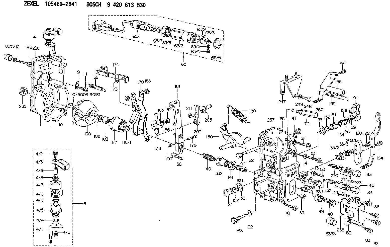
| 1. | [1] | 154004-1300 | GOVERNOR HOUSING |
| 4. | [1] | 154366-6320 | CONTROL LEVER |
| 4. | [1] | 154366-6320 | CONTROL LEVER |
| 4/1. | [1] | 154304-6200 | CONTROL LEVER |
| 4/2. | [2] | 154352-2000 | BLEEDER SCREW |
| 4/2. | [2] | 154352-2000 | BLEEDER SCREW |
| 4/3. | [1] | 154366-6300 | CONTROL LEVER |
| 4/4. | [1] | 029311-0230 | SHIM D18&10.3T0.5 |
| 4/5. | [1] | 154321-1500 | BUSHING |
| 4/6. | [1] | 154327-4100 | COILED SPRING |
| 4/7. | [1] | 154322-0100 | CAP |
| 4/8. | [1] | 029311-0220 | SHIM D18&10.3T0.2 |
| 4/9. | [1] | 154324-2700 | LEVER SHAFT |
| 4/10. | [1] | 029631-0030 | O-RING &9.8W2.3 |
| 9. | [1] | 154353-5601 | PLATE |
| 10. | [4] | 020106-2040 | BLEEDER SCREW M6P1L20 |
| 11. | [4] | 020106-1840 | BLEEDER SCREW M6P1L18 |
| 12. | [1] | 154010-7300 | BLEEDER SCREW M8P1.25L60 |
| 13. | [1] | 013020-6040 | UNION NUT M6P1H5 |
| 14. | [1] | 154011-0100 | HEXAGON NUT |
| 14B. | [1] | 154011-2300 | UNION NUT |
| 35. | [1] | 154514-8220 | GOVERNOR COVER |
| 35/2. | [1] | 154321-2000 | BUSHING |
| 35/3. | [1] | 029621-0080 | PACKING RING |
| 38. | [1] | 154031-3401 | FLAT-HEAD SCREW |
| 39. | [1] | 029201-0160 | UNION NUT |
| 47. | [2] | 154036-1800 | CAPSULE |
| 47. | [2] | 154036-1800 | CAPSULE |
| 48. | [1] | 154010-8200 | BLEEDER SCREW |
| 48B. | [1] | 154010-7100 | BLEEDER SCREW M10P1.25L47 |
| 49. | [1] | 154011-2200 | UNION NUT |
| 50. | [1] | 155615-2300 | FLAT-HEAD SCREW |
| 51. | [5] | 020106-4540 | BLEEDER SCREW M6P1.0L45 |
| 52. | [2] | 020306-6340 | BLEEDER SCREW |
| 53. | [1] | 154010-3100 | BLEEDER SCREW |
| 54. | [2] | 014110-6440 | LOCKING WASHER |
| 65. | [1] | 154610-3120 | RACK SENSOR ASSY |
| 65/1. | [1] | 479743-9520 | RACK SENSOR ASSY |
| 65/2. | [1] | 154614-2500 | JOINT CONNECTION |
| 65/3. | [1] | 154614-2900 | BLOCK |
| 65/4. | [1] | 010234-1040 | HEX-SOCKET-HEAD CAP SCREW |
| 65/5. | [1] | 014110-4440 | LOCKING WASHER |
| 65/6. | [1] | 026524-3040 | GASKET |
| 65/7. | [1] | 029310-6280 | SHIM D11.5&6.4T1.50 |
| 65/8. | [1] | 154614-1900 | UNION NUT |
| 65/9. | [1] | 154614-3300 | BEARING PIN |
| 70. | [1] | 154055-3420 | HEADLESS SCREW |
| 80. | [1] | 154063-4100 | COVER |
| 82. | [1] | 029020-6210 | BLEEDER SCREW |
| 83. | [1] | 029020-6210 | BLEEDER SCREW |
| 84. | [1] | 020006-1640 | BLEEDER SCREW M6P1L16 4T |
| 86. | [1] | 020006-1640 | BLEEDER SCREW M6P1L16 4T |
| 100. | [1] | 154100-9220 | FLYWEIGHT ASSEMBLY |
| 101. | [1] | 025803-1310 | WOODRUFF KEY |
| 102. | [1] | 029321-2020 | LOCKING WASHER |
| 103. | [1] | 139212-0000 | UNION NUT |
| 117. | [1] | 154123-2320 | SLIDING PIECE |
| 118/1. | [0] | 029311-0010 | SHIM D14&10.1T0.2 |
| 118/1. | [0] | 029311-0180 | SHIM D14&10.1T0.3 |
| 118/1. | [0] | 029311-0190 | SHIM D14&10.1T0.40 |
| 118/1. | [0] | 029311-0210 | SHIM D14&10.1T1 |
| 118/1. | [0] | 139410-0000 | SHIM D14.0&10.1T0.5 |
| 118/1. | [0] | 139410-0100 | SHIM D14.0&10.1T1.5 |
| 118/1. | [0] | 139410-3000 | SHIM D14&10.1T2.0 |
| 118/1. | [0] | 139410-3100 | SHIM D14&10.1T3.0 |
| 118/1. | [0] | 139410-3200 | SHIM D14&10.1T4.0 |
| 130. | [1] | 154150-7900 | GOVERNOR SPRING |
| 132. | [1] | 154154-4100 | COILED SPRING |
| 140. | [1] | 154183-6620 | HEADLESS SCREW |
| 141. | [1] | 139218-0100 | UNION NUT |
| 142. | [1] | 154242-5220 | HEADLESS SCREW |
| 143. | [1] | 154242-3200 | UNION NUT |
| 144. | [1] | 026516-2040 | GASKET D19.9&16.2T1 |
| 145. | [1] | 154159-1800 | CAP NUT |
| 146. | [1] | 029331-6130 | GASKET |
| 150. | [1] | 154200-5401 | SWIVELLING LEVER |
| 151. | [1] | 154200-5501 | BUSHING |
| 152. | [2] | 139700-0000 | O-RING |
| 152. | [2] | 139700-0000 | O-RING |
| 153. | [2] | 154354-3900 | LOCKING WASHER |
| 154. | [1] | 139610-0101 | PACKING RING |
| 155. | [1] | 139411-0100 | SHIM D22.0&12.0T0.40 |
| 155. | [1] | 139411-0100 | SHIM D22.0&12.0T0.40 |
| 156. | [0] | 139411-0200 | SHIM D18.0&12.0T0.10 |
| 156B. | [0] | 139411-0300 | SHIM D18.0&12.0T0.20 |
| 156C. | [0] | 139411-0400 | SHIM D18.0&12.0T0.30 |
| 157. | [1] | 154204-3500 | BUSHING |
| 159. | [1] | 025803-1310 | WOODRUFF KEY |
| 162. | [1] | 029331-6050 | GASKET |
| 163. | [1] | 154401-3201 | BLEEDER SCREW |
| 164. | [1] | 154243-0720 | CONTROL LEVER |
| 165. | [1] | 154327-6000 | COILED SPRING |
| 166. | [1] | 029310-8320 | SHIM D16.5&8T0.2 |
| 167. | [1] | 154356-3600 | LOCKING WASHER |
| 170. | [1] | 154217-7020 | FORK LEVER |
| 173. | [1] | 016010-0540 | LOCKING WASHER |
| 174. | [1] | 154230-8120 | STRAP |
| 179. | [1] | 154238-0201 | BEARING PIN |
| 180. | [1] | 016010-0540 | LOCKING WASHER |
| 181. | [1] | 154239-0420 | TENSIONING LEVER |
| 182. | [1] | 154237-1200 | BEARING PIN |
| 183. | [2] | 154237-1300 | BUSHING |
| 190. | [1] | 154360-2800 | CONTROL LEVER |
| 191. | [1] | 154340-4320 | CONTROL LEVER |
| 192. | [1] | 020006-1670 | BLEEDER SCREW M6P1L16 7T |
| 193. | [1] | 154385-1920 | CONTROL LEVER |
| 194. | [2] | 020006-1240 | BLEEDER SCREW M6P1L12 4T |
| 195. | [2] | 154317-9700 | COILED SPRING |
| 196. | [2] | 154156-1300 | TUBE |
| 203/1. | [0] | 029311-0640 | SHIM D26.0&10.2T0.95 |
| 203/1. | [0] | 029311-0650 | SHIM D26.0&10.2T0.20 |
| 203/1. | [0] | 029311-0660 | SHIM D26.0&10.2T0.25 |
| 203/1. | [0] | 029311-0670 | SHIM D26.0&10.2T0.30 |
| 203/1. | [0] | 029311-0680 | SHIM D26.0&10.2T0.35 |
| 203/1. | [0] | 029311-0690 | SHIM D26.0&10.2T0.40 |
| 203/1. | [0] | 029311-0700 | SHIM D26.0&10.2T0.50 |
| 203/1. | [0] | 139410-1400 | SHIM D26&10.2T0.7 |
| 203/1. | [0] | 139410-1500 | SHIM D26&10.2T0.9 |
| 203/1. | [0] | 139410-1600 | SHIM D26&10.2T0.8 |
| 203/1. | [0] | 139410-2700 | SHIM D26&10.2T0.6 |
| 205. | [1] | 154324-4100 | LEVER SHAFT |
| 207. | [1] | 154326-0300 | CONTROL LEVER |
| 211. | [1] | 016010-0840 | LOCKING WASHER |
| 220. | [1] | 154050-8220 | HEADLESS SCREW |
| 221. | [1] | 029201-2140 | UNION NUT |
| 222. | [2] | 026512-1540 | GASKET D15.4&12.2T1.50 |
| 223. | [1] | 154159-1200 | CAP NUT |
| 235. | [1] | 155412-5200 | IMPELLER WHEEL |
| 236. | [1] | 154371-5600 | GASKET |
| 237. | [1] | 154390-0200 | GASKET |
| 238. | [1] | 139700-0100 | O-RING |
| 247. | [1] | 154213-7021 | BRACKET |
| 248. | [1] | 010038-1440 | BLEEDER SCREW M8P1.25L14 |
| 249. | [1] | 014110-8440 | LOCKING WASHER |
| 331. | [1] | 154179-9920 | HEADLESS SCREW |
| 332. | [1] | 139218-0500 | UNION NUT |
| 335. | [1] | 154352-2600 | CAPSULE |
| 336. | [1] | 029331-6030 | GASKET |
| 350. | [1] | 154356-0221 | BRACKET |
| 351. | [3] | 029010-5340 | BLEEDER SCREW |
| 900S. | [1] | 025803-1310 | WOODRUFF KEY |
| 901S. | [1] | 025803-1610 | WOODRUFF KEY |
Cross reference number
Zexel num
Bosch num
Firm num
Name
105489-2641
223005950A HINO
GOVERNOR
K 14JN MECHANICAL GOVERNOR GOV RFD GOV
K 14JN MECHANICAL GOVERNOR GOV RFD GOV
105489-2641
223006100A HINO
GOVERNOR
A K 14JN MECHANICAL GOVERNOR GOV RFD GOV
A K 14JN MECHANICAL GOVERNOR GOV RFD GOV
Information:
The heat baths listed in Chart B meet the specified requirements and can be purchased from:Cole-Parmer Instruments Co.
7425 North Oakpark Ave.
Niles, IL, 60714 U.S.A.
Phone (800) 323-4340
Fax: (708) 647-9660
* Heat Bath Fluid The heat bath fluid must be able to obtain and maintain the required contactor actuation and deactuation temperatures. For the temperatures required for the calibration procedure, silicone fluid must be used. Silicone fluid has a temperature range between 10° C (50° F) and 230° C (446° F). Silicone fluid can be purchased from Cole-Parmer by ordering G-01294-40. The fluid comes in a 3.8 Liter (1 gal) container.
Use extreme caution around heat baths with high temperature fluids. High temperature fluids can cause severe burns.
Calibration Procedure
Use the following procedure to test and calibrate the temperature contactors.1. If connected, disconnect the contactor from the power supply. Mark the terminal location and disconnect the three wires from terminals 1, 2, and 4.
High voltage electrical shock is possible. The contactor must be disconnected from the power supply and the wires disconnected from terminals 1, 2, and 4. Failure to follow this recommendation can result in serious bodily injury.
2. Locate and record the part number of the temperature contactor in Chart A. This will determine the actuation and deactuation temperatures. If the temperature contactor is used in extreme ambient temperatures there will be a scale deviation from the required actuation and deactuation temperatures. Refer to the "Calculating Scale Correction for Severe Temperature Applications" section in this Special Instruction.
Temperature Contactor
(1) Housing cover. (2) Housing cover screws. (3) Temperature probe. (4) Capillary tube.3. Loosen housing cover screws (2) and remove housing cover (1).4. Fill the heat bath unit with silicone fluid and heat it to approximately 5° C (10° F) below the actuation temperature setting. Do not immerse the temperature probe at this time.
Nomenclature Of Internal Parts
(5). Lock screw. (6) Range spindle. (7) Range scale. (8) Differential spindle. (9) Differential scale.5. Loosen lock screw (5).6. Adjust range spindle (6) to a setting above the desired actuation setting determined in Step 2. Determine the setting by using range scale (7).7. Adjust the differential spindle (8) to the approximate mechanical differential temperature using differential scale (9). Mechanical differential temperature is the difference between the actuation and deactuation temperature settings.
Temperature Control Function For Actuation And Deactuation (specifically shown for 7C-3888 Contactor)
Adjusting Temperature and Differential Settings On The Temperature Contactor
This example shows the temperature set at 66° C with an 8° C differential setting. This results in a deactuation temperature of 58° C and actuation temperature of 66° C. (Refer to "Temperature Control Function For Actuation And Deactuation" illustration.)8. Fully immerse temperature probe (3) in the silicone fluid. Increase the heat bath temperature to the specified actuation temperature.9. When the actuation temperature has stabilized, very slowly turn range spindle (6) counterclockwise until the contact actuates. This will be accompanied by an audible "click".
When Contact Actuates, Terminals 1 And 4 Will Have Continuity10. Use a 6V-7070 Multimeter, or equivalent, to verify the actuation of the contactor. Check for continuity between