Information governor
BOSCH
9 420 612 613
9420612613
ZEXEL
105489-2041
1054892041
ISUZU
1157704880
1157704880

Rating:
Scheme ###:
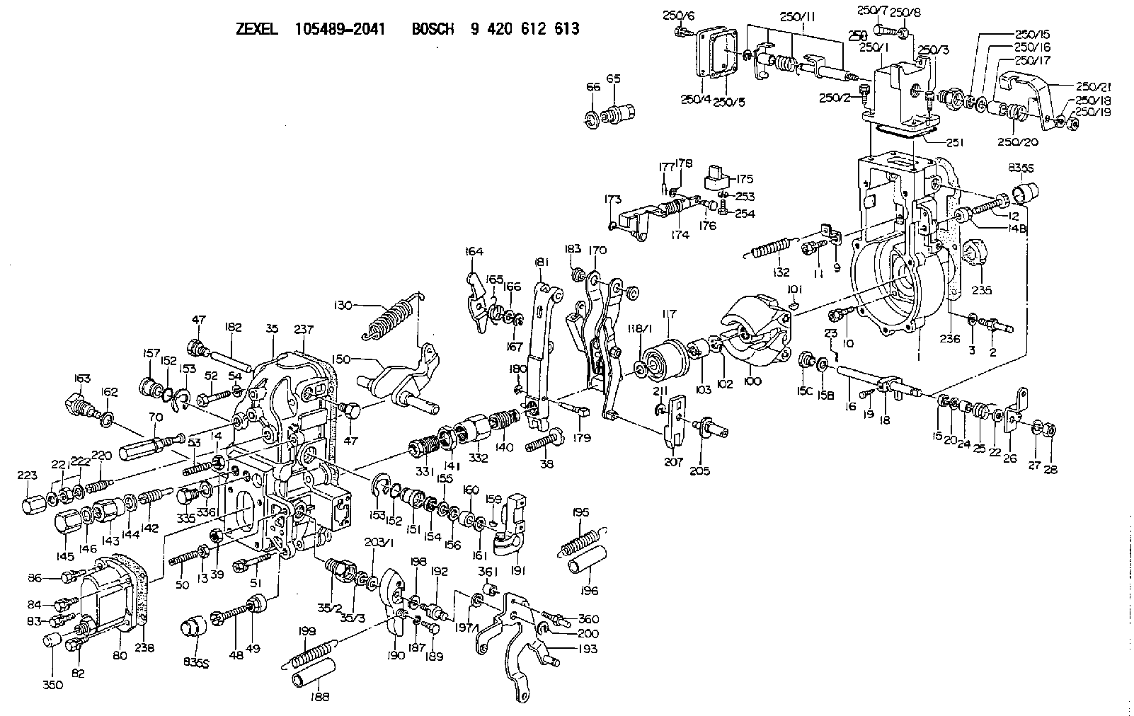
| 1. | [1] | 154004-6320 | GOVERNOR HOUSING |
| 2. | [1] | 154012-4620 | BLEEDER SCREW |
| 3. | [1] | 014110-8440 | LOCKING WASHER |
| 9. | [1] | 154350-6000 | PLATE |
| 10. | [4] | 020106-2040 | BLEEDER SCREW M6P1L20 |
| 11. | [4] | 020106-1840 | BLEEDER SCREW M6P1L18 |
| 12. | [1] | 154010-8100 | BLEEDER SCREW M8P1.25L65 |
| 13. | [1] | 013020-6040 | UNION NUT M6P1H5 |
| 14. | [1] | 154011-0100 | HEXAGON NUT |
| 14B. | [1] | 154011-2300 | UNION NUT |
| 15. | [1] | 139608-0300 | PACKING RING |
| 15B. | [1] | 026516-2040 | GASKET D19.9&16.2T1 |
| 15C. | [1] | 154372-3900 | CAPSULE |
| 16. | [1] | 155003-3320 | LEVER SHAFT |
| 18. | [1] | 155003-2101 | CONTROL LEVER |
| 19. | [1] | 155006-0100 | BLEEDER SCREW |
| 20. | [1] | 139408-0700 | SHIM |
| 22. | [0] | 029310-8040 | SHIM D13.5&8T0.2 |
| 22B. | [0] | 029310-8050 | SHIM D13.5&8T0.5 |
| 23. | [1] | 025520-1210 | SPLIT PIN |
| 24. | [1] | 154206-2000 | BUSHING |
| 25. | [1] | 154327-8600 | COILED SPRING |
| 26. | [1] | 154380-0600 | CONTROL LEVER |
| 27. | [1] | 014110-8440 | LOCKING WASHER |
| 28. | [1] | 013020-8040 | UNION NUT M8P1.25H7 |
| 35. | [1] | 154515-3420 | GOVERNOR COVER |
| 35/2. | [1] | 154321-2000 | BUSHING |
| 35/3. | [1] | 139610-0600 | PACKING RING |
| 38. | [1] | 154031-3401 | FLAT-HEAD SCREW |
| 39. | [1] | 029201-0160 | UNION NUT |
| 47. | [2] | 154036-1800 | CAPSULE |
| 47. | [2] | 154036-1800 | CAPSULE |
| 48. | [1] | 154010-7900 | BLEEDER SCREW M10P1.25L58 |
| 48B. | [1] | 154010-6000 | BLEEDER SCREW M10P1.25L55 |
| 49. | [1] | 154011-2200 | UNION NUT |
| 50. | [1] | 155615-2300 | FLAT-HEAD SCREW |
| 51. | [5] | 020106-4540 | BLEEDER SCREW M6P1.0L45 |
| 52. | [2] | 029010-6850 | BLEEDER SCREW |
| 53. | [1] | 154010-0100 | FLAT-HEAD SCREW |
| 54. | [2] | 014110-6440 | LOCKING WASHER |
| 65. | [1] | 153021-5000 | CAP |
| 66. | [1] | 139524-0000 | GASKET |
| 70. | [1] | 154055-2520 | HEADLESS SCREW |
| 80. | [1] | 154063-5320 | COVER |
| 82. | [1] | 029020-6210 | BLEEDER SCREW |
| 83. | [1] | 020006-1640 | BLEEDER SCREW M6P1L16 4T |
| 84. | [1] | 029020-6210 | BLEEDER SCREW |
| 86. | [1] | 020006-1640 | BLEEDER SCREW M6P1L16 4T |
| 100. | [1] | 154100-9220 | FLYWEIGHT ASSEMBLY |
| 101. | [1] | 025803-1610 | WOODRUFF KEY |
| 102. | [1] | 029321-2020 | LOCKING WASHER |
| 103. | [1] | 139212-0000 | UNION NUT |
| 117. | [1] | 154123-2320 | SLIDING PIECE |
| 118/1. | [0] | 029311-0010 | SHIM D14&10.1T0.2 |
| 118/1. | [0] | 029311-0180 | SHIM D14&10.1T0.3 |
| 118/1. | [0] | 029311-0190 | SHIM D14&10.1T0.40 |
| 118/1. | [0] | 029311-0210 | SHIM D14&10.1T1 |
| 118/1. | [0] | 139410-0000 | SHIM D14.0&10.1T0.5 |
| 118/1. | [0] | 139410-0100 | SHIM D14.0&10.1T1.5 |
| 118/1. | [0] | 139410-3000 | SHIM D14&10.1T2.0 |
| 118/1. | [0] | 139410-3100 | SHIM D14&10.1T3.0 |
| 118/1. | [0] | 139410-3200 | SHIM D14&10.1T4.0 |
| 130. | [1] | 154150-7900 | GOVERNOR SPRING |
| 132. | [1] | 154154-0701 | COILED SPRING |
| 140. | [1] | 154183-2120 | HEADLESS SCREW |
| 141. | [1] | 139218-0100 | UNION NUT |
| 142. | [1] | 154242-3520 | HEADLESS SCREW |
| 143. | [1] | 154242-3200 | UNION NUT |
| 144. | [1] | 139516-0100 | GASKET |
| 145. | [1] | 154159-1800 | CAP NUT |
| 146. | [1] | 139516-0100 | GASKET |
| 150. | [1] | 154200-5701 | SWIVELLING LEVER |
| 151. | [1] | 154200-5501 | BUSHING |
| 152. | [2] | 139719-0000 | O-RING |
| 152. | [2] | 139719-0000 | O-RING |
| 153. | [2] | 154354-3900 | LOCKING WASHER |
| 153. | [2] | 154354-3900 | LOCKING WASHER |
| 154. | [1] | 139612-0000 | PACKING RING |
| 155. | [1] | 139411-0100 | SHIM D22.0&12.0T0.40 |
| 156. | [0] | 139411-0200 | SHIM D18.0&12.0T0.10 |
| 156B. | [0] | 139411-0300 | SHIM D18.0&12.0T0.20 |
| 156C. | [0] | 139411-0400 | SHIM D18.0&12.0T0.30 |
| 157. | [1] | 154204-3500 | BUSHING |
| 159. | [1] | 025803-1310 | WOODRUFF KEY |
| 160. | [1] | 154206-2300 | BUSHING |
| 161. | [0] | 154206-2400 | PLAIN WASHER D20.5&12.2T1 |
| 162. | [1] | 139516-0100 | GASKET |
| 163. | [1] | 154401-3201 | BLEEDER SCREW |
| 164. | [1] | 154243-0720 | CONTROL LEVER |
| 165. | [1] | 154327-6000 | COILED SPRING |
| 166. | [1] | 029310-8320 | SHIM D16.5&8T0.2 |
| 167. | [1] | 154356-3600 | LOCKING WASHER |
| 170. | [1] | 154217-6520 | FORK LEVER |
| 173. | [1] | 016010-0540 | LOCKING WASHER |
| 174. | [1] | 154235-1220 | STRAP |
| 175. | [1] | 154232-1821 | CONNECTOR |
| 176. | [1] | 154222-4900 | BEARING PIN |
| 177. | [1] | 155402-3800 | SAFETY PIN |
| 178. | [1] | 029310-5170 | SHIM D8&5.3T0.5 |
| 179. | [1] | 154238-0701 | BEARING PIN |
| 180. | [1] | 016010-0540 | LOCKING WASHER |
| 181. | [1] | 154239-2420 | TENSIONING LEVER |
| 182. | [1] | 154237-1200 | BEARING PIN |
| 183. | [2] | 154237-1800 | BUSHING |
| 187. | [1] | 014110-6440 | LOCKING WASHER |
| 188. | [1] | 154156-1500 | TUBE |
| 189. | [1] | 154357-6320 | BLEEDER SCREW |
| 190. | [1] | 154360-2800 | CONTROL LEVER |
| 191. | [1] | 154340-1920 | CONTROL LEVER |
| 192. | [1] | 154371-8300 | BLEEDER SCREW |
| 193. | [1] | 154369-8420 | CONTROL LEVER |
| 195. | [2] | 154317-0600 | COILED SPRING |
| 196. | [2] | 154156-0600 | TUBE |
| 197/1. | [0] | 029310-8610 | SHIM D10.5&8.5T0.1 |
| 197/1. | [0] | 029310-8620 | SHIM D10.5&8.5T0.15 |
| 197/1. | [0] | 029310-8630 | SHIM D10.5&8.5T0.2 |
| 197/1. | [0] | 029310-8650 | SHIM D10.5&8.5T0.5 |
| 198. | [1] | 014110-8440 | LOCKING WASHER |
| 199. | [1] | 154317-0900 | COILED SPRING |
| 200. | [1] | 016010-0740 | LOCKING WASHER |
| 203/1. | [0] | 029311-0640 | SHIM D26.0&10.2T0.95 |
| 203/1. | [0] | 029311-0650 | SHIM D26.0&10.2T0.20 |
| 203/1. | [0] | 029311-0660 | SHIM D26.0&10.2T0.25 |
| 203/1. | [0] | 029311-0670 | SHIM D26.0&10.2T0.30 |
| 203/1. | [0] | 029311-0680 | SHIM D26.0&10.2T0.35 |
| 203/1. | [0] | 029311-0690 | SHIM D26.0&10.2T0.40 |
| 203/1. | [0] | 029311-0700 | SHIM D26.0&10.2T0.50 |
| 203/1. | [0] | 139410-1400 | SHIM D26&10.2T0.7 |
| 203/1. | [0] | 139410-1500 | SHIM D26&10.2T0.9 |
| 203/1. | [0] | 139410-1600 | SHIM D26&10.2T0.8 |
| 203/1. | [0] | 139410-2700 | SHIM D26&10.2T0.6 |
| 205. | [1] | 154324-3500 | LEVER SHAFT |
| 207. | [1] | 154326-7320 | CONTROL LEVER |
| 211. | [1] | 016010-0840 | LOCKING WASHER |
| 220. | [1] | 154050-6820 | HEADLESS SCREW |
| 221. | [1] | 029201-2140 | UNION NUT |
| 222. | [2] | 139512-0000 | GASKET D17.2&12.2T1.0 |
| 223. | [1] | 154159-1200 | CAP NUT |
| 235. | [1] | 155412-5200 | IMPELLER WHEEL |
| 236. | [1] | 154371-5600 | GASKET |
| 237. | [1] | 154390-0200 | GASKET |
| 238. | [1] | 154390-1400 | GASKET |
| 250. | [1] | 154414-8720 | STARTING FUEL AIDS |
| 250/1. | [1] | 154414-7720 | GOVERNOR HOUSING |
| 250/2. | [3] | 020106-1640 | BLEEDER SCREW M6P1.0L14 |
| 250/3. | [1] | 029020-6210 | BLEEDER SCREW |
| 250/4. | [1] | 154414-5300 | COVER |
| 250/5. | [1] | 154414-5400 | GASKET |
| 250/6. | [4] | 020105-1040 | BLEEDER SCREW M5P0.8L10 |
| 250/7. | [1] | 153141-1500 | BLEEDER SCREW |
| 250/8. | [1] | 029240-6010 | UNION NUT M6P1.0H5* |
| 250/11. | [1] | 154414-8520 | CONTROL LEVER |
| 250/15. | [1] | 139610-0600 | PACKING RING |
| 250/16. | [0] | 029311-0700 | SHIM D26.0&10.2T0.50 |
| 250/17. | [1] | 154414-5900 | BUSHING |
| 250/18. | [1] | 014110-6440 | LOCKING WASHER |
| 250/19. | [1] | 013010-8040 | UNION NUT M8P0.9H7 |
| 250/20. | [1] | 154414-8100 | COILED SPRING |
| 250/21. | [1] | 154414-8600 | CONTROL LEVER |
| 251. | [1] | 154419-2500 | SEAL RING |
| 253. | [1] | 029320-5020 | LOCKING WASHER |
| 254. | [1] | 010535-1040 | FLAT-HEAD SCREW M5P0.8L10 |
| 331. | [1] | 154188-0220 | HEADLESS SCREW |
| 332. | [1] | 139218-0500 | UNION NUT |
| 335. | [1] | 154352-2600 | CAPSULE |
| 336. | [1] | 139516-0100 | GASKET |
| 350. | [1] | 154359-4200 | CAP |
| 360. | [1] | 010006-2540 | BLEEDER SCREW M6P1L25 4T |
| 361. | [1] | 154357-3100 | BUSHING |
| 835S. | [2] | 154062-1700 | CAP D20L32 |
| 835S. | [2] | 154062-1700 | CAP D20L32 |
Include in #1:
106671-1661
as GOVERNOR
Cross reference number
Zexel num
Bosch num
Firm num
Name
Information:
Literature Information
This manual contains safety, operation instructions, lubrication and maintenance information. This manual should be stored in or near the engine area in a literature holder or literature storage area. Read, study and keep it with the literature and engine information.Some photographs or illustrations in this manual show details or attachments that may be different from your engine. Guards and covers may have been removed for illustrative purposes. Continuing improvement and advancement of product design may have caused changes to your engine which are not included in this manual. Whenever a question arises regarding your engine, or this manual, please consult your Caterpillar dealer for the latest available information. Safety
The safety section lists basic safety precautions. In addition, this section identifies hazardous, warning situations. Read and understand the basic precautions listed in the safety section before operating or performing lubrication, maintenance and repair on this product.Operation
Operating techniques outlined in this manual are basic. Skill and techniques develop as the operator gains knowledge of the engine and its capabilities, and to assist with developing the skills and techniques required to operate the engine more efficiently and economically.The operation section is a reference for operators, and photographs and illustrations guide the operator through procedures of inspecting, starting, operating and stopping the engine. This section also includes a discussion of GSC display window indicators, features and controls, and electronic diagnostic information.Maintenance
The maintenance section is a guide to engine care. The illustrated, step-by-step instructions are grouped by fuel consumption, service hours and/or calendar time maintenance intervals. Items in the Maintenance Schedule are referenced to detailed instructions that follow.Use fuel consumption or service hours to determine intervals. Calendar intervals shown (daily, annually, etc.) may be used instead of service meter intervals if they provide more convenient schedules and approximate the indicated service meter reading.Recommended service should always be performed at the service hour interval. The actual operating environment of the engine also governs the maintenance schedule. Therefore, under extremely severe, dusty, wet or freezing cold operating conditions, more frequent lubrication and maintenance than is specified in the Maintenance Schedule may be necessary.The Maintenance Schedule items are organized for a Preventive Maintenance Management Program. If the Preventive Maintenance Program is followed, a periodic tune-up is not required. The implementation of a Preventive Maintenance Management Program should minimize operating costs through cost avoidances resulting from reductions in unscheduled downtime and failures.Maintenance Intervals
Perform maintenance on items at multiples of the original requirement. Each level and/or individual items in each level should be shifted ahead or back depending upon your specific maintenance practices, operation and application. We recommend that the maintenance schedules be reproduced and displayed near the engine as a convenient reminder. We also recommend that a maintenance record be maintained as part of the engine's permanent record. See the Maintenance Records section in this manual for information regarding documents that are generally accepted as proof of maintenance or repair. Your authorized Caterpillar engine dealer can assist you in tailoring your Maintenance Schedule