Information governor
BOSCH
9 420 612 933
9420612933
ZEXEL
105489-2031
1054892031
ISUZU
1157703581
1157703581
Rating:
Scheme ###:
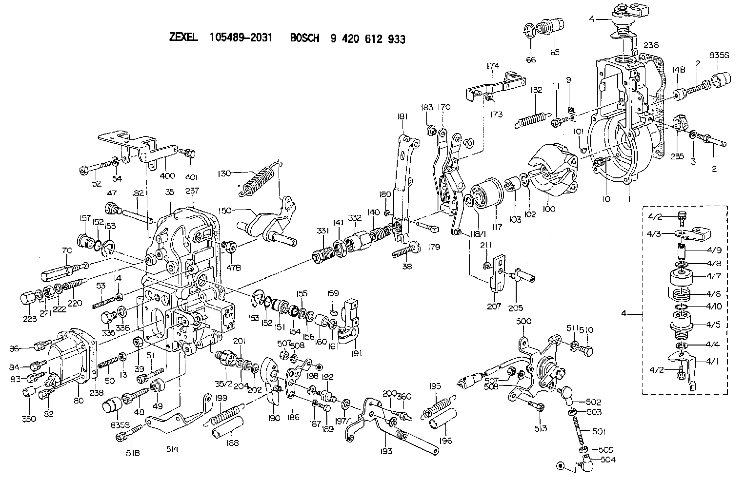
| 1. | [1] | 154004-2000 | GOVERNOR HOUSING |
| 2. | [1] | 154012-2820 | BLEEDER SCREW |
| 3. | [1] | 014110-8440 | LOCKING WASHER |
| 4. | [1] | 154380-3820 | CONTROL LEVER |
| 4. | [1] | 154380-3820 | CONTROL LEVER |
| 4/1. | [1] | 154304-6200 | CONTROL LEVER |
| 4/2. | [2] | 154352-2000 | BLEEDER SCREW |
| 4/2. | [2] | 154352-2000 | BLEEDER SCREW |
| 4/3. | [1] | 154366-1900 | CONTROL LEVER |
| 4/4. | [1] | 029311-0230 | SHIM D18&10.3T0.5 |
| 4/5. | [1] | 154321-1500 | BUSHING |
| 4/6. | [1] | 154327-2901 | COILED SPRING |
| 4/7. | [1] | 154322-0100 | CAP |
| 4/8. | [1] | 029311-0220 | SHIM D18&10.3T0.2 |
| 4/9. | [1] | 154324-2700 | LEVER SHAFT |
| 4/10. | [1] | 139710-0300 | O-RING |
| 9. | [1] | 154353-5601 | PLATE |
| 10. | [4] | 020106-2040 | BLEEDER SCREW M6P1L20 |
| 11. | [4] | 020106-1840 | BLEEDER SCREW M6P1L18 |
| 12. | [1] | 154010-7200 | BLEEDER SCREW M8P1.25L62 |
| 13. | [1] | 013020-6040 | UNION NUT M6P1H5 |
| 14. | [1] | 154011-0100 | HEXAGON NUT |
| 14B. | [1] | 154011-2300 | UNION NUT |
| 35. | [1] | 154515-3120 | GOVERNOR COVER |
| 35/2. | [1] | 154321-3000 | BUSHING |
| 38. | [1] | 154031-3401 | FLAT-HEAD SCREW |
| 39. | [1] | 029201-0160 | UNION NUT |
| 47. | [1] | 154036-1800 | CAPSULE |
| 47B. | [1] | 154036-1900 | CAPSULE |
| 48. | [1] | 154010-6000 | BLEEDER SCREW M10P1.25L55 |
| 48B. | [1] | 154010-7700 | BLEEDER SCREW M10P1.25L51 |
| 49. | [1] | 154011-2200 | UNION NUT |
| 50. | [1] | 155615-2300 | FLAT-HEAD SCREW |
| 51. | [3] | 020106-4540 | BLEEDER SCREW M6P1.0L45 |
| 51B. | [2] | 020106-5040 | BLEEDER SCREW |
| 52. | [2] | 010006-6040 | BLEEDER SCREW |
| 53. | [1] | 154010-0100 | FLAT-HEAD SCREW |
| 54. | [2] | 014110-6440 | LOCKING WASHER |
| 65. | [1] | 153021-5000 | CAP |
| 66. | [1] | 139524-0000 | GASKET |
| 70. | [1] | 154055-2020 | HEADLESS SCREW |
| 80. | [1] | 154063-5320 | COVER |
| 82. | [1] | 029020-6210 | BLEEDER SCREW |
| 83. | [1] | 020006-1640 | BLEEDER SCREW M6P1L16 4T |
| 84. | [1] | 029020-6210 | BLEEDER SCREW |
| 86. | [1] | 020006-1640 | BLEEDER SCREW M6P1L16 4T |
| 100. | [1] | 154100-9220 | FLYWEIGHT ASSEMBLY |
| 101. | [1] | 025803-1610 | WOODRUFF KEY |
| 102. | [1] | 029321-2020 | LOCKING WASHER |
| 103. | [1] | 139212-0000 | UNION NUT |
| 117. | [1] | 154123-2320 | SLIDING PIECE |
| 118/1. | [0] | 029311-0010 | SHIM D14&10.1T0.2 |
| 118/1. | [0] | 029311-0180 | SHIM D14&10.1T0.3 |
| 118/1. | [0] | 029311-0190 | SHIM D14&10.1T0.40 |
| 118/1. | [0] | 029311-0210 | SHIM D14&10.1T1 |
| 118/1. | [0] | 139410-0000 | SHIM D14.0&10.1T0.5 |
| 118/1. | [0] | 139410-0100 | SHIM D14.0&10.1T1.5 |
| 118/1. | [0] | 139410-3000 | SHIM D14&10.1T2.0 |
| 118/1. | [0] | 139410-3100 | SHIM D14&10.1T3.0 |
| 118/1. | [0] | 139410-3200 | SHIM D14&10.1T4.0 |
| 130. | [1] | 154150-9400 | GOVERNOR SPRING |
| 132. | [1] | 154154-0701 | COILED SPRING |
| 140. | [1] | 154183-2720 | HEADLESS SCREW |
| 141. | [1] | 139218-0100 | UNION NUT |
| 150. | [1] | 154200-5701 | SWIVELLING LEVER |
| 151. | [1] | 154200-5501 | BUSHING |
| 152. | [2] | 139719-0000 | O-RING |
| 152. | [2] | 139719-0000 | O-RING |
| 153. | [2] | 154354-3900 | LOCKING WASHER |
| 153. | [2] | 154354-3900 | LOCKING WASHER |
| 154. | [1] | 139612-0000 | PACKING RING |
| 155. | [1] | 139411-0100 | SHIM D22.0&12.0T0.40 |
| 156. | [0] | 139411-0200 | SHIM D18.0&12.0T0.10 |
| 156B. | [0] | 139411-0300 | SHIM D18.0&12.0T0.20 |
| 156C. | [0] | 139411-0400 | SHIM D18.0&12.0T0.30 |
| 157. | [1] | 154204-3500 | BUSHING |
| 159. | [1] | 025803-1310 | WOODRUFF KEY |
| 160. | [1] | 154206-2300 | BUSHING |
| 161. | [0] | 154206-2400 | PLAIN WASHER D20.5&12.2T1 |
| 170. | [1] | 154217-5520 | FORK LEVER |
| 173. | [1] | 016010-0540 | LOCKING WASHER |
| 174. | [1] | 154230-8120 | STRAP |
| 179. | [1] | 154238-0701 | BEARING PIN |
| 180. | [1] | 016010-0540 | LOCKING WASHER |
| 181. | [1] | 154239-0020 | TENSIONING LEVER |
| 182. | [1] | 154237-1200 | BEARING PIN |
| 183. | [2] | 154237-1800 | BUSHING |
| 186. | [1] | 154374-4500 | CONTROL LEVER |
| 187. | [1] | 014110-6440 | LOCKING WASHER |
| 188. | [1] | 154156-1500 | TUBE |
| 189. | [1] | 154357-6520 | BLEEDER SCREW |
| 190. | [1] | 154369-5900 | CONTROL LEVER |
| 191. | [1] | 154340-1920 | CONTROL LEVER |
| 192. | [1] | 154357-4501 | BLEEDER SCREW |
| 193. | [1] | 154385-9620 | CONTROL LEVER |
| 195. | [1] | 154317-0500 | COILED SPRING |
| 196. | [1] | 154156-1700 | TUBE |
| 197/1. | [0] | 029310-8610 | SHIM D10.5&8.5T0.1 |
| 197/1. | [0] | 029310-8620 | SHIM D10.5&8.5T0.15 |
| 197/1. | [0] | 029310-8630 | SHIM D10.5&8.5T0.2 |
| 197/1. | [0] | 029310-8650 | SHIM D10.5&8.5T0.5 |
| 198. | [1] | 014110-8440 | LOCKING WASHER |
| 199. | [1] | 154317-0900 | COILED SPRING |
| 200. | [1] | 016010-0740 | LOCKING WASHER |
| 201. | [1] | 139411-0600 | SHIM |
| 202. | [1] | 159238-3000 | LOCKING WASHER |
| 204. | [1] | 139610-0800 | PACKING RING |
| 205. | [1] | 154324-5300 | LEVER SHAFT |
| 207. | [1] | 154326-7320 | CONTROL LEVER |
| 211. | [1] | 016010-0840 | LOCKING WASHER |
| 220. | [1] | 154050-6820 | HEADLESS SCREW |
| 221. | [1] | 029201-2140 | UNION NUT |
| 222. | [2] | 139512-0000 | GASKET D17.2&12.2T1.0 |
| 223. | [1] | 154159-1200 | CAP NUT |
| 235. | [1] | 155412-5200 | IMPELLER WHEEL |
| 236. | [1] | 154371-5600 | GASKET |
| 237. | [1] | 154390-0200 | GASKET |
| 238. | [1] | 154390-1400 | GASKET |
| 331. | [1] | 154179-5920 | HEADLESS SCREW |
| 332. | [1] | 139218-0500 | UNION NUT |
| 335. | [1] | 154352-2600 | CAPSULE |
| 336. | [1] | 029331-6030 | GASKET |
| 350. | [1] | 154359-4200 | CAP |
| 360. | [1] | 154357-7000 | BEARING PIN |
| 400. | [1] | 154359-0020 | BRACKET |
| 401. | [1] | 020006-1240 | BLEEDER SCREW M6P1L12 4T |
| 500. | [1] | 154600-8720 | LOAD SENSOR ASSY |
| 501. | [1] | 154604-8600 | LEVER SHAFT |
| 502. | [1] | 159227-4000 | JOINT CONNECTION |
| 503. | [1] | 013020-5240 | UNION NUT M5P0.8H4 |
| 504. | [1] | 159227-4100 | JOINT CONNECTION |
| 505. | [1] | 029200-5130 | UNION NUT |
| 507. | [2] | 013010-5240 | UNION NUT M5P0.8H4 |
| 507. | [2] | 013010-5240 | UNION NUT M5P0.8H4 |
| 508. | [2] | 014110-5440 | LOCKING WASHER |
| 508. | [2] | 014110-5440 | LOCKING WASHER |
| 510. | [1] | 010010-1440 | BLEEDER SCREW M10P1.5L14 |
| 511. | [1] | 014111-0440 | LOCKING WASHER |
| 513. | [1] | 020106-1240 | BLEEDER SCREW M6P1.0L12 |
| 514. | [1] | 154372-0000 | BRACKET |
Include in #1:
106693-6011
as GOVERNOR
Cross reference number
Zexel num
Bosch num
Firm num
Name
Information:
You must read and understand the warnings and instructions contained in the Safety section of this manual before performing any operation or maintenance procedures.Cooling System (Extended Life Coolant Only)
Drain/Flush/Replace Coolant
Only clean water is needed to clean and flush the cooling system when ELC is drained and replaced.Drain
1. Stop the engine and allow the engine to cool. Loosen the coolant filler cap slowly to relieve any pressure, and remove the cap.2. Open the cooling system drain valve (if equipped). If not equipped with a drain valve, remove the engine block drain plug. Remove the oil cooler drain plug. Remove the drain plug from the bottom of the water pump housing. Allow the coolant to drain.
Dispose of used engine coolant properly or recycle. Various methods have been proposed to reclaim used coolant for reuse in engine cooling systems. The full distillation procedure is the only method acceptable by Caterpillar to reclaim the used coolant.
For information regarding disposal and recycling of used coolant, contact your Caterpillar dealer or contact Caterpillar Service Technology Group:Outside Illinois: 1-800-542-TOOLInside Illinois: 1-800-541-TOOLCanada: 1-800-523-TOOLFlush
3. Flush the cooling system with clean water to remove any debris.4. Close the drain valve (if equipped). Clean the drain plugs. Clean the drain plug receptacles. Install the drain plugs. Refer to the Torque Specifications section in this manual.5. Fill the cooling system with clean water. Install the filler cap. Operate the engine until the temperature reaches 49 to 66°C (150 to 120°F).6. Stop the engine and allow the engine to cool. Loosen the cooling system filler cap slowly to relieve any pressure, and remove the cap. Open the drain valve (if equipped) or remove the cooling system drain plugs. Allow the water to drain. Flush the cooling system with clean water.7. Repeat steps 5 and 6.Fill
8. Fill the cooling system with ELC. Refer to the refill capacities chart in this manual for the amount of ELC needed to refill your system.9. Start and run the engine with the filler cap removed. Allow the ELC to warm, the thermostat to open, and the coolant level to stabilize. Add ELC if necessary to bring the coolant to the proper level.10. Clean the filler cap. Clean the filler cap receptacle. Inspect the filler cap gasket. If the gasket is damaged, discard the old filler cap and install a new filler cap. If the gasket is not damaged, use a 9S-8140 Pressurized Pump Group to pressure test the filler cap. The correct filler cap pressure is stamped on the face of the filler cap. If the filler cap does not hold the correct pressure, install a new filler cap.11. Install the filler cap. Start the engine. Inspect for coolant leaks and proper operating temperature.