Information governor
BOSCH
9 420 612 932
9420612932
ZEXEL
105489-2030
1054892030

Rating:
Scheme ###:
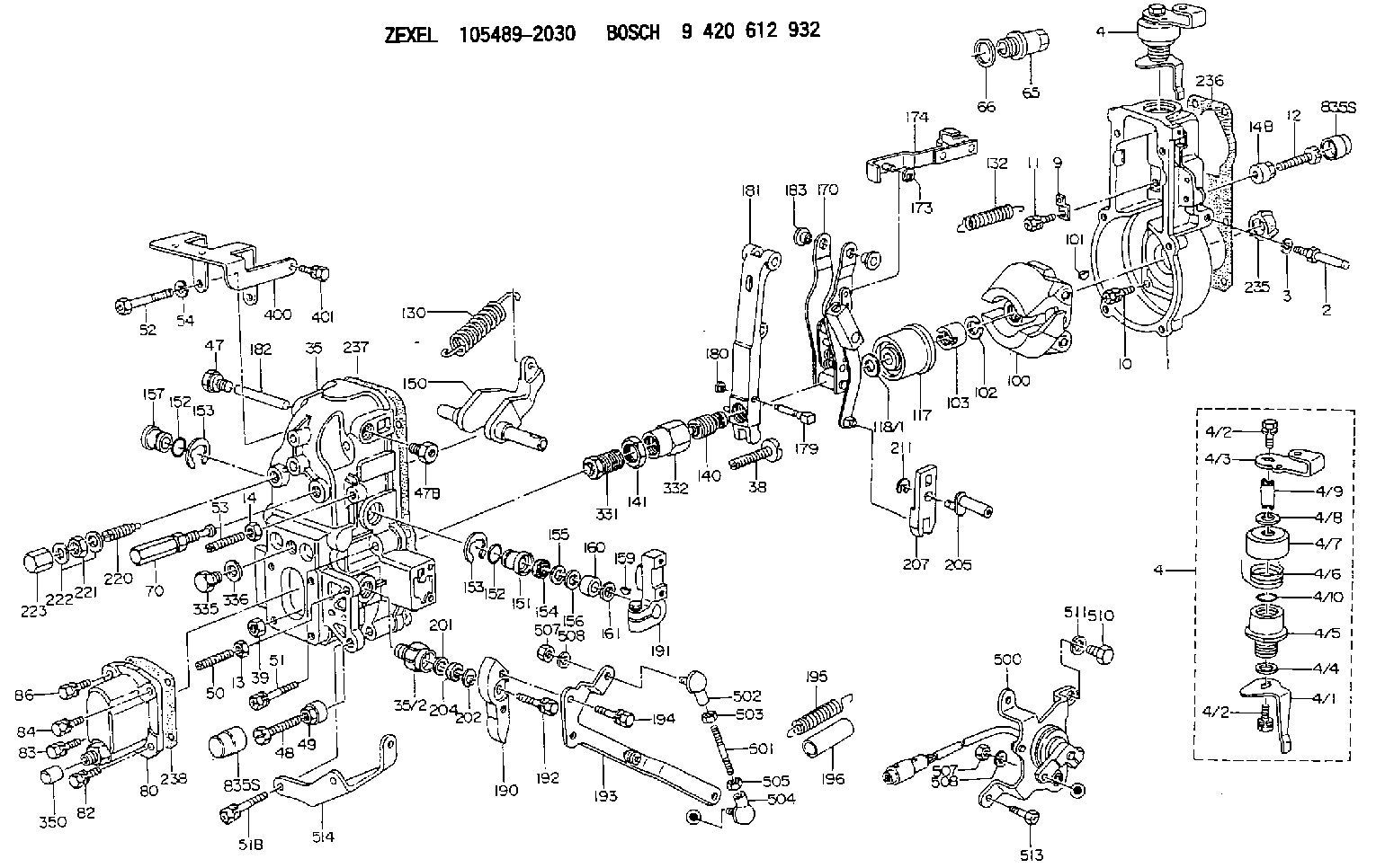
| 1. | [1] | 154004-2000 | GOVERNOR HOUSING |
| 2. | [1] | 154012-3820 | BLEEDER SCREW |
| 3. | [1] | 014110-8440 | LOCKING WASHER |
| 4. | [1] | 154380-3820 | CONTROL LEVER |
| 4. | [1] | 154380-3820 | CONTROL LEVER |
| 4/1. | [1] | 154304-6200 | CONTROL LEVER |
| 4/2. | [2] | 154352-2000 | BLEEDER SCREW |
| 4/2. | [2] | 154352-2000 | BLEEDER SCREW |
| 4/3. | [1] | 154366-1900 | CONTROL LEVER |
| 4/4. | [1] | 029311-0230 | SHIM D18&10.3T0.5 |
| 4/5. | [1] | 154321-1500 | BUSHING |
| 4/6. | [1] | 154327-2901 | COILED SPRING |
| 4/7. | [1] | 154322-0100 | CAP |
| 4/8. | [1] | 029311-0220 | SHIM D18&10.3T0.2 |
| 4/9. | [1] | 154324-2700 | LEVER SHAFT |
| 4/10. | [1] | 139710-0300 | O-RING |
| 9. | [1] | 154353-5601 | PLATE |
| 10. | [4] | 020106-2040 | BLEEDER SCREW M6P1L20 |
| 11. | [4] | 020106-1840 | BLEEDER SCREW M6P1L18 |
| 12. | [1] | 154010-7200 | BLEEDER SCREW M8P1.25L62 |
| 13. | [1] | 013020-6040 | UNION NUT M6P1H5 |
| 14. | [1] | 154011-0100 | HEXAGON NUT |
| 14B. | [1] | 154011-2300 | UNION NUT |
| 35. | [1] | 154515-3120 | GOVERNOR COVER |
| 35/2. | [1] | 154321-3000 | BUSHING |
| 38. | [1] | 154031-3401 | FLAT-HEAD SCREW |
| 39. | [1] | 029201-0160 | UNION NUT |
| 47. | [1] | 154036-1800 | CAPSULE |
| 47B. | [1] | 154036-1900 | CAPSULE |
| 48. | [1] | 154010-6000 | BLEEDER SCREW M10P1.25L55 |
| 48B. | [1] | 154010-7700 | BLEEDER SCREW M10P1.25L51 |
| 49. | [1] | 154011-2200 | UNION NUT |
| 50. | [1] | 155615-2300 | FLAT-HEAD SCREW |
| 51. | [3] | 020106-4540 | BLEEDER SCREW M6P1.0L45 |
| 51B. | [2] | 020106-5040 | BLEEDER SCREW |
| 52. | [2] | 010006-6040 | BLEEDER SCREW |
| 53. | [1] | 154010-0100 | FLAT-HEAD SCREW |
| 54. | [2] | 014110-6440 | LOCKING WASHER |
| 65. | [1] | 153021-5000 | CAP |
| 66. | [1] | 139524-0000 | GASKET |
| 70. | [1] | 154055-2020 | HEADLESS SCREW |
| 80. | [1] | 154063-5320 | COVER |
| 82. | [1] | 029020-6210 | BLEEDER SCREW |
| 83. | [1] | 020006-1640 | BLEEDER SCREW M6P1L16 4T |
| 84. | [1] | 029020-6210 | BLEEDER SCREW |
| 86. | [1] | 020006-1640 | BLEEDER SCREW M6P1L16 4T |
| 100. | [1] | 154100-9220 | FLYWEIGHT ASSEMBLY |
| 101. | [1] | 025803-1610 | WOODRUFF KEY |
| 102. | [1] | 029321-2020 | LOCKING WASHER |
| 103. | [1] | 139212-0000 | UNION NUT |
| 117. | [1] | 154123-2320 | SLIDING PIECE |
| 118/1. | [0] | 029311-0010 | SHIM D14&10.1T0.2 |
| 118/1. | [0] | 029311-0180 | SHIM D14&10.1T0.3 |
| 118/1. | [0] | 029311-0190 | SHIM D14&10.1T0.40 |
| 118/1. | [0] | 029311-0210 | SHIM D14&10.1T1 |
| 118/1. | [0] | 139410-0000 | SHIM D14.0&10.1T0.5 |
| 118/1. | [0] | 139410-0100 | SHIM D14.0&10.1T1.5 |
| 118/1. | [0] | 139410-3000 | SHIM D14&10.1T2.0 |
| 118/1. | [0] | 139410-3100 | SHIM D14&10.1T3.0 |
| 118/1. | [0] | 139410-3200 | SHIM D14&10.1T4.0 |
| 130. | [1] | 154150-9400 | GOVERNOR SPRING |
| 132. | [1] | 154154-0701 | COILED SPRING |
| 140. | [1] | 154183-2720 | HEADLESS SCREW |
| 141. | [1] | 139218-0100 | UNION NUT |
| 150. | [1] | 154200-5701 | SWIVELLING LEVER |
| 151. | [1] | 154200-5501 | BUSHING |
| 152. | [2] | 139719-0000 | O-RING |
| 152. | [2] | 139719-0000 | O-RING |
| 153. | [2] | 154354-3900 | LOCKING WASHER |
| 153. | [2] | 154354-3900 | LOCKING WASHER |
| 154. | [1] | 139612-0000 | PACKING RING |
| 155. | [1] | 139411-0100 | SHIM D22.0&12.0T0.40 |
| 156. | [0] | 139411-0200 | SHIM D18.0&12.0T0.10 |
| 156B. | [0] | 139411-0300 | SHIM D18.0&12.0T0.20 |
| 156C. | [0] | 139411-0400 | SHIM D18.0&12.0T0.30 |
| 157. | [1] | 154204-3500 | BUSHING |
| 159. | [1] | 025803-1310 | WOODRUFF KEY |
| 160. | [1] | 154206-2300 | BUSHING |
| 161. | [0] | 154206-2400 | PLAIN WASHER D20.5&12.2T1 |
| 170. | [1] | 154217-5520 | FORK LEVER |
| 173. | [1] | 016010-0540 | LOCKING WASHER |
| 174. | [1] | 154230-8120 | STRAP |
| 179. | [1] | 154238-0701 | BEARING PIN |
| 180. | [1] | 016010-0540 | LOCKING WASHER |
| 181. | [1] | 154239-0020 | TENSIONING LEVER |
| 182. | [1] | 154237-1200 | BEARING PIN |
| 183. | [2] | 154237-1800 | BUSHING |
| 190. | [1] | 154369-5900 | CONTROL LEVER |
| 191. | [1] | 154340-1920 | CONTROL LEVER |
| 192. | [1] | 020006-1670 | BLEEDER SCREW M6P1L16 7T |
| 193. | [1] | 154369-8320 | CONTROL LEVER |
| 194. | [2] | 020006-2540 | BLEEDER SCREW M6P1L25 |
| 195. | [1] | 154317-0500 | COILED SPRING |
| 196. | [1] | 154156-1700 | TUBE |
| 201. | [1] | 139411-0600 | SHIM |
| 202. | [1] | 159238-3000 | LOCKING WASHER |
| 204. | [1] | 139610-0800 | PACKING RING |
| 205. | [1] | 154324-5300 | LEVER SHAFT |
| 207. | [1] | 154326-7320 | CONTROL LEVER |
| 211. | [1] | 016010-0840 | LOCKING WASHER |
| 220. | [1] | 154050-6820 | HEADLESS SCREW |
| 221. | [1] | 029201-2140 | UNION NUT |
| 222. | [2] | 139512-0000 | GASKET D17.2&12.2T1.0 |
| 223. | [1] | 154159-1200 | CAP NUT |
| 235. | [1] | 155412-5200 | IMPELLER WHEEL |
| 236. | [1] | 154371-5600 | GASKET |
| 237. | [1] | 154390-0200 | GASKET |
| 238. | [1] | 154390-1400 | GASKET |
| 331. | [1] | 154179-5920 | HEADLESS SCREW |
| 332. | [1] | 139218-0500 | UNION NUT |
| 335. | [1] | 154352-2600 | CAPSULE |
| 336. | [1] | 029331-6030 | GASKET |
| 350. | [1] | 154359-4200 | CAP |
| 400. | [1] | 154359-0020 | BRACKET |
| 401. | [1] | 020006-1240 | BLEEDER SCREW M6P1L12 4T |
| 500. | [1] | 154600-8720 | LOAD SENSOR ASSY |
| 501. | [1] | 154604-6500 | LEVER SHAFT |
| 502. | [1] | 159227-4000 | JOINT CONNECTION |
| 503. | [1] | 013020-5240 | UNION NUT M5P0.8H4 |
| 504. | [1] | 159227-4100 | JOINT CONNECTION |
| 505. | [1] | 029200-5130 | UNION NUT |
| 507. | [2] | 013010-5240 | UNION NUT M5P0.8H4 |
| 507. | [2] | 013010-5240 | UNION NUT M5P0.8H4 |
| 508. | [2] | 014110-5440 | LOCKING WASHER |
| 508. | [2] | 014110-5440 | LOCKING WASHER |
| 510. | [1] | 010010-1440 | BLEEDER SCREW M10P1.5L14 |
| 511. | [1] | 014111-0440 | LOCKING WASHER |
| 513. | [1] | 020106-1240 | BLEEDER SCREW M6P1.0L12 |
| 514. | [1] | 154372-0000 | BRACKET |
Include in #1:
106693-6010
as GOVERNOR
Cross reference number
Zexel num
Bosch num
Firm num
Name
Information:
Abnormal engine running, smoke emission, and engine knock can be symptoms of nozzle malfunction. Each nozzle must be isolated one at a time in order to determine the malfunctioning nozzle.1. Start the engine.
A nozzle will be damaged if the top of the nozzle turns in the body. The engine will be damaged if a defective nozzle is used because the fuel spray pattern that comes out of the nozzle will be incorrect. Nozzles can be permanently damaged by twisting if only one wrench is used to loosen or tighten the fuel line nuts. Do NOT let the tops of the nozzles turn when the fuel lines are loosened. Use one wrench to hold the nozzle and another to loosen the fuel line nut.
2. Loosen each fuel line nut at the fuel injection pump, one at a time. A cloth or similar material must be used to prevent fuel from spraying on the hot exhaust components. Tighten each nut before loosening the next nut.3. A defective nozzle may be identified when a fuel line nut is loosened and: * the exhaust smoking is partially or completely eliminated* engine performance is not affectedA nozzle suspected of being defective should be removed. A new nozzle should be installed in the cylinder to determine if the removed nozzle is defective.Removing and Installing Fuel Injection Nozzles
Special tooling is required to remove and install nozzles. Refer to the Service Manual for information. Consult with your Caterpillar dealer for assistance.Inspect, Rebuild, or Exchange
If the engine is operated until the components fail, additional engine damage can result. Caterpillar recommends that the following components be inspected in order to ensure reliable engine performance:* Jacket Water Pump* Raw/Sea Water Pump* Alternator* Starting Motor* Air Compressor Caterpillar RecommendationTo minimize downtime, Caterpillar recommends the use of Remanufactured components (subject to availability) as the most cost effective option. Removal and InstallationRefer to the Service Manual or contact your Caterpillar dealer for assistance with removal and installation of engine components.Water Pumps
A failed water pump might cause severe engine overheating problems that could result in cracks in the cylinder head, a piston seizure or other potential damage to the engine.Visually inspect the water pump for leaks. If leaking is observed, replace all seals. Refer to the service manual for the disassembly and assembly procedure.Inspect the component for wear, cracks, pin holes and proper operation. Refer to the service manual or consult with your Caterpillar dealer if repair or replacement is needed.Raw/Sea Water Pump
If the pump flow is reduced or if the pump can not self-prime, check for excessive wear of the impellers and the port plates. Refer to the Service Manual for the disassembly and assembly procedure. Rebuild or exchange the pump if necessary.Alternator
Caterpillar recommends a scheduled inspection of the alternator. Inspect the alternator for loose connections and proper battery charging. Inspect the ammeter gauge during engine operation to ensure the batteries and/or electrical system is performing correctly. Make repairs as necessary. Refer to the Service Manual.Check the alternator and battery charger for