Information governor
BOSCH
F 019 Z2F 008
f019z2f008
ZEXEL
105489-1520
1054891520
ISUZU
1157702880
1157702880
Rating:
Scheme ###:
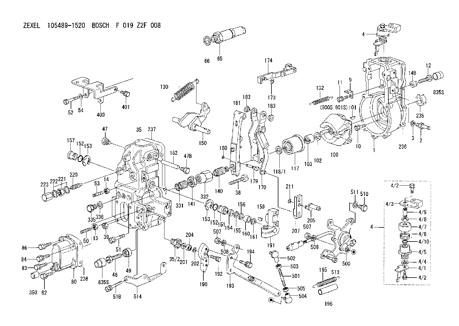
| 1. | [1] | 154004-2000 | GOVERNOR HOUSING |
| 2. | [1] | 154012-3820 | BLEEDER SCREW |
| 3. | [1] | 014110-8440 | LOCKING WASHER |
| 4. | [1] | 154366-1920 | CONTROL LEVER |
| 4. | [1] | 154366-1920 | CONTROL LEVER |
| 4/1. | [1] | 154304-6200 | CONTROL LEVER |
| 4/2. | [2] | 154352-2000 | BLEEDER SCREW |
| 4/2. | [2] | 154352-2000 | BLEEDER SCREW |
| 4/3. | [1] | 154366-1900 | CONTROL LEVER |
| 4/4. | [1] | 029311-0230 | SHIM D18&10.3T0.5 |
| 4/5. | [1] | 154321-1500 | BUSHING |
| 4/6. | [1] | 154327-2901 | COILED SPRING |
| 4/7. | [1] | 154322-0100 | CAP |
| 4/8. | [1] | 029311-0220 | SHIM D18&10.3T0.2 |
| 4/9. | [1] | 154324-2700 | LEVER SHAFT |
| 4/10. | [1] | 029631-0030 | O-RING &9.8W2.3 |
| 9. | [1] | 154353-5601 | PLATE |
| 10. | [4] | 020106-2040 | BLEEDER SCREW M6P1L20 |
| 11. | [4] | 020106-1840 | BLEEDER SCREW M6P1L18 |
| 12. | [1] | 154010-8100 | BLEEDER SCREW M8P1.25L65 |
| 13. | [1] | 029240-6010 | UNION NUT M6P1.0H5* |
| 14. | [1] | 154011-0100 | HEXAGON NUT |
| 14B. | [1] | 154011-2300 | UNION NUT |
| 35. | [1] | 154515-0020 | GOVERNOR COVER |
| 35/2. | [1] | 154321-3000 | BUSHING |
| 38. | [1] | 154031-3401 | FLAT-HEAD SCREW |
| 39. | [1] | 029201-0160 | UNION NUT |
| 47. | [1] | 154036-1800 | CAPSULE |
| 47B. | [1] | 154036-1900 | CAPSULE |
| 48. | [1] | 154010-6000 | BLEEDER SCREW M10P1.25L55 |
| 48B. | [1] | 154010-7700 | BLEEDER SCREW M10P1.25L51 |
| 49. | [1] | 154011-2200 | UNION NUT |
| 50. | [1] | 155615-2300 | FLAT-HEAD SCREW |
| 51. | [3] | 020106-4540 | BLEEDER SCREW M6P1.0L45 |
| 51B. | [2] | 020106-5040 | BLEEDER SCREW |
| 52. | [2] | 010006-6040 | BLEEDER SCREW |
| 53. | [1] | 154010-0100 | FLAT-HEAD SCREW |
| 54. | [2] | 014110-6440 | LOCKING WASHER |
| 65. | [1] | 153043-5220 | STOPPING DEVICE |
| 66. | [1] | 026524-3040 | GASKET |
| 80. | [1] | 154063-5320 | COVER |
| 82. | [1] | 029020-6210 | BLEEDER SCREW |
| 83. | [1] | 020006-1640 | BLEEDER SCREW M6P1L16 4T |
| 84. | [1] | 029020-6210 | BLEEDER SCREW |
| 86. | [1] | 020006-1640 | BLEEDER SCREW M6P1L16 4T |
| 100. | [1] | 154100-9220 | FLYWEIGHT ASSEMBLY |
| 101. | [1] | 025803-1310 | WOODRUFF KEY |
| 102. | [1] | 029321-2020 | LOCKING WASHER |
| 103. | [1] | 139212-0000 | UNION NUT |
| 117. | [1] | 154123-2320 | SLIDING PIECE |
| 118/1. | [0] | 029311-0010 | SHIM D14&10.1T0.2 |
| 118/1. | [0] | 029311-0180 | SHIM D14&10.1T0.3 |
| 118/1. | [0] | 029311-0190 | SHIM D14&10.1T0.40 |
| 118/1. | [0] | 029311-0210 | SHIM D14&10.1T1 |
| 118/1. | [0] | 139410-0000 | SHIM D14.0&10.1T0.5 |
| 118/1. | [0] | 139410-0100 | SHIM D14.0&10.1T1.5 |
| 118/1. | [0] | 139410-3000 | SHIM D14&10.1T2.0 |
| 118/1. | [0] | 139410-3100 | SHIM D14&10.1T3.0 |
| 118/1. | [0] | 139410-3200 | SHIM D14&10.1T4.0 |
| 130. | [1] | 154150-9000 | GOVERNOR SPRING |
| 132. | [1] | 154154-0701 | COILED SPRING |
| 140. | [1] | 154183-2720 | HEADLESS SCREW |
| 141. | [1] | 139218-0100 | UNION NUT |
| 150. | [1] | 154200-5701 | SWIVELLING LEVER |
| 151. | [1] | 154200-5501 | BUSHING |
| 152. | [2] | 139700-0000 | O-RING |
| 152. | [2] | 139700-0000 | O-RING |
| 153. | [2] | 154354-3900 | LOCKING WASHER |
| 153. | [2] | 154354-3900 | LOCKING WASHER |
| 154. | [1] | 139610-0101 | PACKING RING |
| 155. | [1] | 139411-0100 | SHIM D22.0&12.0T0.40 |
| 156. | [0] | 139411-0200 | SHIM D18.0&12.0T0.10 |
| 156B. | [0] | 139411-0300 | SHIM D18.0&12.0T0.20 |
| 156C. | [0] | 139411-0400 | SHIM D18.0&12.0T0.30 |
| 157. | [1] | 154204-3500 | BUSHING |
| 159. | [1] | 025803-1310 | WOODRUFF KEY |
| 160. | [1] | 154206-2300 | BUSHING |
| 161. | [0] | 154206-2400 | PLAIN WASHER D20.5&12.2T1 |
| 170. | [1] | 154216-8321 | FORK LEVER |
| 173. | [1] | 016010-0540 | LOCKING WASHER |
| 174. | [1] | 154230-8120 | STRAP |
| 179. | [1] | 154238-0701 | BEARING PIN |
| 180. | [1] | 016010-0540 | LOCKING WASHER |
| 181. | [1] | 154236-9220 | TENSIONING LEVER |
| 182. | [1] | 154237-1200 | BEARING PIN |
| 183. | [2] | 154237-1800 | BUSHING |
| 183. | [2] | 154237-1800 | BUSHING |
| 190. | [1] | 154369-1800 | CONTROL LEVER |
| 191. | [1] | 154340-1920 | CONTROL LEVER |
| 192. | [1] | 020006-1670 | BLEEDER SCREW M6P1L16 7T |
| 193. | [1] | 154369-1920 | CONTROL LEVER |
| 194. | [2] | 020006-2540 | BLEEDER SCREW M6P1L25 |
| 195. | [1] | 154317-0500 | COILED SPRING |
| 196. | [1] | 154156-1700 | TUBE |
| 201. | [1] | 139411-0600 | SHIM |
| 202. | [1] | 159238-3000 | LOCKING WASHER |
| 204. | [1] | 139610-0800 | PACKING RING |
| 205. | [1] | 154324-5300 | LEVER SHAFT |
| 207. | [1] | 154326-6522 | CONTROL LEVER |
| 211. | [1] | 016010-0840 | LOCKING WASHER |
| 220. | [1] | 154050-6820 | HEADLESS SCREW |
| 221. | [1] | 029201-2140 | UNION NUT |
| 222. | [2] | 139512-0000 | GASKET D17.2&12.2T1.0 |
| 223. | [1] | 154159-1200 | CAP NUT |
| 235. | [1] | 155412-5200 | IMPELLER WHEEL |
| 236. | [1] | 154371-5600 | GASKET |
| 237. | [1] | 154390-0200 | GASKET |
| 238. | [1] | 154390-1400 | GASKET |
| 331. | [1] | 154179-5020 | HEADLESS SCREW |
| 332. | [1] | 139218-0500 | UNION NUT |
| 335. | [1] | 154352-2600 | CAPSULE |
| 336. | [1] | 029331-6030 | GASKET |
| 350. | [1] | 154359-4200 | CAP |
| 400. | [1] | 154359-0020 | BRACKET |
| 401. | [1] | 020106-1240 | BLEEDER SCREW M6P1.0L12 |
| 500. | [1] | 154600-8720 | LOAD SENSOR ASSY |
| 501. | [1] | 154604-6500 | LEVER SHAFT |
| 502. | [1] | 159227-4000 | JOINT CONNECTION |
| 503. | [1] | 013020-5240 | UNION NUT M5P0.8H4 |
| 504. | [1] | 159227-4100 | JOINT CONNECTION |
| 505. | [1] | 029200-5130 | UNION NUT |
| 507. | [2] | 013010-5240 | UNION NUT M5P0.8H4 |
| 507. | [2] | 013010-5240 | UNION NUT M5P0.8H4 |
| 508. | [2] | 014110-5440 | LOCKING WASHER |
| 508. | [2] | 014110-5440 | LOCKING WASHER |
| 510. | [1] | 010010-1440 | BLEEDER SCREW M10P1.5L14 |
| 511. | [1] | 014111-0440 | LOCKING WASHER |
| 513. | [1] | 020106-1240 | BLEEDER SCREW M6P1.0L12 |
| 514. | [1] | 154372-0000 | BRACKET |
| 835S. | [2] | 154062-1700 | CAP D20L32 |
| 835S. | [2] | 154062-1700 | CAP D20L32 |
| 900S. | [1] | 025803-1310 | WOODRUFF KEY |
| 901S. | [1] | 025803-1610 | WOODRUFF KEY |
Include in #1:
106693-1880
as GOVERNOR
Cross reference number
Zexel num
Bosch num
Firm num
Name
Information:
Exhaust brakes should not be used as a primary or service brake.
Auxiliary engine braking devices are approved for use on the 3176 Engine.Compression Brake
Operation (Jacobs Brake)
Compression brakes should not be used as a primary or service brake.Do not allow the engine to exceed 2300 rpm. However, engines equipped with a compression brake should not normally be operated above 2100 rpm.
The compression brake is an engine attachment that converts a diesel engine into an air compressor. Its function is to slow the vehicle and reduce brake wear.Operating Controls-Compression Brake
The compression brake controls may include a dash mounted module or an ON/OFF switch and a three position switch with "LO," "MED" and "HI" depending on how many cylinders of braking desired. Refer to the OEM vehicle manual for the type of operating controls that your vehicle is equipped with.Some applications are equipped with a multi-position switch to provide variable retarding capability. Operators should become familiar with the controls on their vehicles.The 3176 ECM monitors the clutch, brake, throttle position and engine rpm to determine when the compression brake can operate. It may take up to two seconds before compression brake activates.Since the compression brake is most effective at rated engine speed, gear selection is very important. Gearing down the vehicle, within the limits of rated engine speed, makes the engine brake a more effective retarder. Maximum retarding occurs at higher engine speeds.However, a compression brake equipped engine should not be operated above 2100 rpm.Cruise Control (If Equipped) OFF
With the Cruise Control (CC) in the OFF position the compression brake will function like any vehicle and engine that is not equipped with Cruise Control (CC).Cruise Control (If Equipped) ON
The driver must apply the service brake approximately two seconds and then release the service brake pedal. If the retarder "LATCH" mode has been programmed, the retarder will continue to slow the vehicle. To release or deactivate the retarder, the clutch or throttle foot pedal must be depressed or the engine rpm drop to 950 rpm.When using "COAST" mode, the compression brake should activate within two seconds after the brake pedal is applied and remain on as long as the brake pedal is applied. At the time the brake pedal is applied, the Cruise Control (CC) will deactivate.For information on adjustment to compression brake slave piston lash, refer to the Maintenance Schedule for Engine Valve Lash.Refer to the Truck Engine Application and Installation Guide, LEBT8121 April, 1988 for more information. Refer to the Systems Operation Test and Adjust in the Service Manual or to Jacobs Brake Troubleshooting Manual, SENR4251 for information regarding this auxiliary braking system.