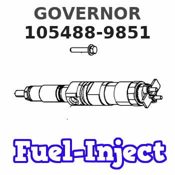
Information governor
BOSCH
F 019 Z4E 965
f019z4e965
ZEXEL
105488-9851
1054889851
HINO
223003671A
223003671a
Rating:
Scheme ###:
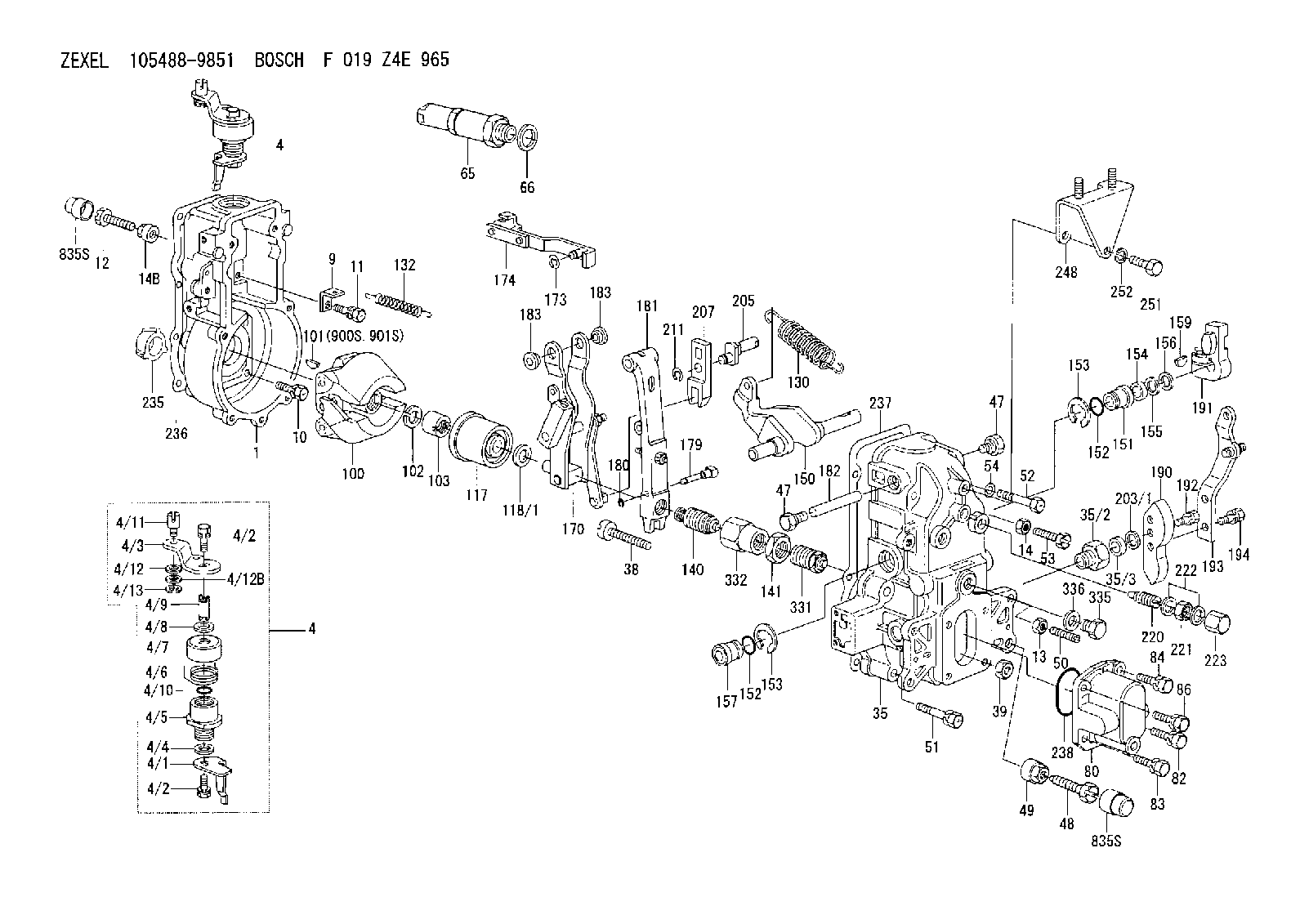
| 1. | [1] | 154004-1300 | GOVERNOR HOUSING |
| 4. | [1] | 154304-8221 | CONTROL LEVER |
| 4. | [1] | 154304-8221 | CONTROL LEVER |
| 4/1. | [1] | 154304-6200 | CONTROL LEVER |
| 4/2. | [2] | 154352-2000 | BLEEDER SCREW |
| 4/2. | [2] | 154352-2000 | BLEEDER SCREW |
| 4/3. | [1] | 154304-3300 | CONTROL LEVER |
| 4/4. | [1] | 029311-0230 | SHIM D18&10.3T0.5 |
| 4/5. | [1] | 154321-1500 | BUSHING |
| 4/6. | [1] | 154327-4100 | COILED SPRING |
| 4/7. | [1] | 154322-0100 | CAP |
| 4/8. | [1] | 029311-0220 | SHIM D18&10.3T0.2 |
| 4/9. | [1] | 154324-2700 | LEVER SHAFT |
| 4/10. | [1] | 029631-0030 | O-RING &9.8W2.3 |
| 4/11. | [1] | 154353-3701 | BEARING PIN |
| 4/12. | [1] | 014010-6140 | PLAIN WASHER D13&6.5T1 |
| 4/12B. | [0] | 029310-6040 | SHIM |
| 4/13. | [1] | 016010-0540 | LOCKING WASHER |
| 9. | [1] | 154353-5601 | PLATE |
| 10. | [4] | 020106-2040 | BLEEDER SCREW M6P1L20 |
| 11. | [4] | 020106-1840 | BLEEDER SCREW M6P1L18 |
| 12. | [1] | 154010-7300 | BLEEDER SCREW M8P1.25L60 |
| 13. | [1] | 013020-6040 | UNION NUT M6P1H5 |
| 14. | [1] | 154011-0100 | HEXAGON NUT |
| 14B. | [1] | 154011-2300 | UNION NUT |
| 35. | [1] | 154513-3920 | GOVERNOR COVER |
| 35/2. | [1] | 154321-2000 | BUSHING |
| 35/3. | [1] | 029621-0080 | PACKING RING |
| 38. | [1] | 154031-3401 | FLAT-HEAD SCREW |
| 39. | [1] | 029201-0160 | UNION NUT |
| 47. | [2] | 154036-1800 | CAPSULE |
| 47. | [2] | 154036-1800 | CAPSULE |
| 48. | [1] | 154010-7700 | BLEEDER SCREW M10P1.25L51 |
| 48B. | [1] | 154010-7100 | BLEEDER SCREW M10P1.25L47 |
| 49. | [1] | 154011-2200 | UNION NUT |
| 50. | [1] | 155615-2300 | FLAT-HEAD SCREW |
| 51. | [5] | 020106-4540 | BLEEDER SCREW M6P1.0L45 |
| 52. | [2] | 020306-6340 | BLEEDER SCREW |
| 53. | [1] | 154010-3100 | BLEEDER SCREW |
| 54. | [2] | 014110-6440 | LOCKING WASHER |
| 65. | [1] | 153043-5820 | STOPPING DEVICE |
| 66. | [1] | 026524-3040 | GASKET |
| 80. | [1] | 154063-4100 | COVER |
| 82. | [1] | 029020-6210 | BLEEDER SCREW |
| 83. | [1] | 029020-6210 | BLEEDER SCREW |
| 84. | [1] | 020006-1640 | BLEEDER SCREW M6P1L16 4T |
| 86. | [1] | 020006-1640 | BLEEDER SCREW M6P1L16 4T |
| 100. | [1] | 154100-9220 | FLYWEIGHT ASSEMBLY |
| 101. | [1] | 025803-1310 | WOODRUFF KEY |
| 102. | [1] | 029321-2020 | LOCKING WASHER |
| 103. | [1] | 139212-0000 | UNION NUT |
| 117. | [1] | 154123-2320 | SLIDING PIECE |
| 118/1. | [0] | 029311-0010 | SHIM D14&10.1T0.2 |
| 118/1. | [0] | 029311-0180 | SHIM D14&10.1T0.3 |
| 118/1. | [0] | 029311-0190 | SHIM D14&10.1T0.40 |
| 118/1. | [0] | 029311-0210 | SHIM D14&10.1T1 |
| 118/1. | [0] | 139410-0000 | SHIM D14.0&10.1T0.5 |
| 118/1. | [0] | 139410-0100 | SHIM D14.0&10.1T1.5 |
| 118/1. | [0] | 139410-3000 | SHIM D14&10.1T2.0 |
| 118/1. | [0] | 139410-3100 | SHIM D14&10.1T3.0 |
| 118/1. | [0] | 139410-3200 | SHIM D14&10.1T4.0 |
| 130. | [1] | 154150-9000 | GOVERNOR SPRING |
| 132. | [1] | 154154-0701 | COILED SPRING |
| 140. | [1] | 154183-0020 | HEADLESS SCREW |
| 141. | [1] | 139218-0100 | UNION NUT |
| 150. | [1] | 154200-5401 | SWIVELLING LEVER |
| 151. | [1] | 154200-5501 | BUSHING |
| 152. | [2] | 139700-0000 | O-RING |
| 152. | [2] | 139700-0000 | O-RING |
| 153. | [2] | 154354-3900 | LOCKING WASHER |
| 153. | [2] | 154354-3900 | LOCKING WASHER |
| 154. | [1] | 139610-0101 | PACKING RING |
| 155. | [1] | 139411-0100 | SHIM D22.0&12.0T0.40 |
| 156. | [0] | 139411-0200 | SHIM D18.0&12.0T0.10 |
| 156B. | [0] | 139411-0300 | SHIM D18.0&12.0T0.20 |
| 156C. | [0] | 139411-0400 | SHIM D18.0&12.0T0.30 |
| 157. | [1] | 154204-3500 | BUSHING |
| 159. | [1] | 025803-1310 | WOODRUFF KEY |
| 170. | [1] | 154216-8420 | FORK LEVER |
| 173. | [1] | 016010-0540 | LOCKING WASHER |
| 174. | [1] | 154230-8120 | STRAP |
| 179. | [1] | 154238-0201 | BEARING PIN |
| 180. | [1] | 016010-0540 | LOCKING WASHER |
| 181. | [1] | 154236-6320 | TENSIONING LEVER |
| 182. | [1] | 154237-1200 | BEARING PIN |
| 183. | [2] | 154237-1300 | BUSHING |
| 183. | [2] | 154237-1300 | BUSHING |
| 190. | [1] | 154360-2800 | CONTROL LEVER |
| 191. | [1] | 154340-4320 | CONTROL LEVER |
| 192. | [1] | 020006-1670 | BLEEDER SCREW M6P1L16 7T |
| 193. | [1] | 154361-4420 | CONTROL LEVER |
| 194. | [2] | 020006-1240 | BLEEDER SCREW M6P1L12 4T |
| 203/1. | [0] | 029311-0640 | SHIM D26.0&10.2T0.95 |
| 203/1. | [0] | 029311-0650 | SHIM D26.0&10.2T0.20 |
| 203/1. | [0] | 029311-0660 | SHIM D26.0&10.2T0.25 |
| 203/1. | [0] | 029311-0670 | SHIM D26.0&10.2T0.30 |
| 203/1. | [0] | 029311-0680 | SHIM D26.0&10.2T0.35 |
| 203/1. | [0] | 029311-0690 | SHIM D26.0&10.2T0.40 |
| 203/1. | [0] | 029311-0700 | SHIM D26.0&10.2T0.50 |
| 203/1. | [0] | 139410-1400 | SHIM D26&10.2T0.7 |
| 203/1. | [0] | 139410-1500 | SHIM D26&10.2T0.9 |
| 203/1. | [0] | 139410-1600 | SHIM D26&10.2T0.8 |
| 203/1. | [0] | 139410-2700 | SHIM D26&10.2T0.6 |
| 205. | [1] | 154324-4100 | LEVER SHAFT |
| 207. | [1] | 154326-0300 | CONTROL LEVER |
| 211. | [1] | 016010-0840 | LOCKING WASHER |
| 220. | [1] | 154050-6220 | HEADLESS SCREW |
| 221. | [1] | 029201-2140 | UNION NUT |
| 222. | [2] | 026512-1540 | GASKET D15.4&12.2T1.50 |
| 223. | [1] | 154159-1200 | CAP NUT |
| 235. | [1] | 155412-5200 | IMPELLER WHEEL |
| 236. | [1] | 154371-5600 | GASKET |
| 237. | [1] | 154390-0200 | GASKET |
| 238. | [1] | 139700-0100 | O-RING |
| 248. | [1] | 154213-7021 | BRACKET |
| 251. | [1] | 010038-1440 | BLEEDER SCREW M8P1.25L14 |
| 252. | [1] | 014110-8440 | LOCKING WASHER |
| 331. | [1] | 154179-5720 | HEADLESS SCREW |
| 332. | [1] | 139218-0200 | UNION NUT |
| 335. | [1] | 154352-2600 | CAPSULE |
| 336. | [1] | 029331-6030 | GASKET |
| 835S. | [2] | 154062-1700 | CAP D20L32 |
| 835S. | [2] | 154062-1700 | CAP D20L32 |
| 900S. | [1] | 025803-1310 | WOODRUFF KEY |
| 901S. | [1] | 025803-1610 | WOODRUFF KEY |
Include in #1:
106871-3821
as GOVERNOR
Cross reference number
Zexel num
Bosch num
Firm num
Name
105488-9851
223003671A HINO
GOVERNOR
K 14JN MECHANICAL GOVERNOR GOV RFD GOV
K 14JN MECHANICAL GOVERNOR GOV RFD GOV
Information:
Tachometer Drive
Use a short fiber grease, No. 2 Grade for most temperatures, or No. 0 or No. 1 for extremely low temperatures. Wipe surrounding area with a clean rag before removing plug. Remove plug. Install grease fitting. Apply two strokes of lubricant through the fitting. Remove grease fitting. Replace plug.Governor Control Cross Shaft Bearings (1673)
Engines Before 69D3625)
Use a short fiber grease No. 2 Grade for most temperatures, or No. 0 or No. 1 for extremely low temperatures. Apply 1 stroke of lubricant through fitting at each end of shaft.Valve Adjustment
1673C
Make valve adjustment with engine stopped and cold. Remove the flywheel timing cover and rotate flywheel in direction of engine rotation until "TC 1-6 cyl" mark aligns with timing pointer. Remove valve cover and observe position of valves to determine if No. 1 or No. 6 piston is on compression stroke. Both the inlet and exhaust valves will be closed on compression stroke.1. With No. 1 piston at TDC on compression, check lash on exhaust valves for cylinders 1, 3 and 5, and inlet valves for cylinders 1, 2 and 4.2. To adjust, loosen valve adjusting locknut and turn adjusting screw to allow feeler gauge to pass between top of valve stem and the valve rocker arm.3. Set lash at .015" (0.38 mm) for inlet and .025" (0.63 mm) for exhaust valves.4. Tighten adjusting screw locknut and check lash clearance.5. Turn flywheel 360° in direction of engine rotation. Align flywheel timing mark with pointer. No. 6 cylinder will be at TDC compression stroke (valves closed).6. Check lash on exhaust valves for cylinders 2, 4 and 6, and inlet valves for cylinders 3, 5 and 6. Adjust valves if necessary.1674
Make valve lash adjustment with engine stopped. TDC of the No. 1 piston on the compression stroke is the reference point. The No. 1 piston will be at TDC when the No. 1 and No. 6 flywheel timing mark aligns with the timing pointer. Compression stroke is when all the No. 1 piston valves are closed.1. With No. 1 piston at TDC compression stroke, adjust lash on 1, 3 and 5 exhaust and 1, 2 and 4 inlet valves.2. Turn adjusting screw counterclockwise 2 clicks or more to provide clearance between rocker assembly and valve.3. Turn adjusting screw clockwise to obtain zero lash. There should be no free rocker movement or adjusting screw button lateral movement. The adjusting screw button can still be rotated by finger pressure even when it is in contact with valve stem and clearance is zero. Turning the adjusting screw clockwise beyond this point will force the valve off its seat, and final lash setting will be incorrect.4. To adjust, turn adjustment screw counterclockwise 10 clicks (.020") (0.51 mm) for the exhaust valves and 4 clicks (.008") (0.20 mm) for the inlet valves. (One click is equal to .002") (0.05 mm).5. Turn crankshaft 360° clockwise, (direction of normal rotation) viewing from front. Align flywheel timing mark with timing pointer. a) Adjust 2, 4 and 6 exhaust