Information governor
BOSCH
F 019 Z1E 644
f019z1e644
ZEXEL
105488-9391
1054889391
Rating:
Scheme ###:
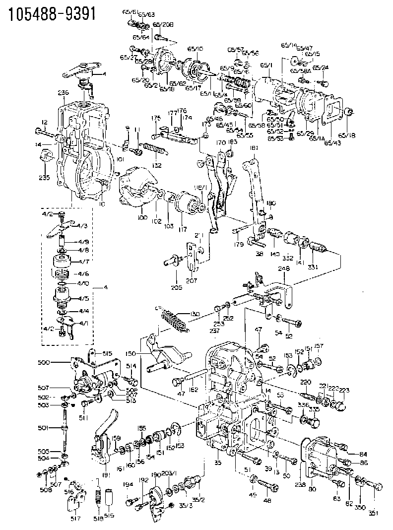
| 1. | [1] | 154004-0100 | GOVERNOR HOUSING |
| 4. | [1] | 154365-0320 | CONTROL LEVER |
| 4. | [1] | 154365-0320 | CONTROL LEVER |
| 4/1. | [1] | 154304-0100 | CONTROL LEVER |
| 4/2. | [2] | 154352-2000 | BLEEDER SCREW |
| 4/2. | [2] | 154352-2000 | BLEEDER SCREW |
| 4/3. | [1] | 154365-0300 | CONTROL LEVER |
| 4/4. | [1] | 029311-0230 | SHIM D18&10.3T0.5 |
| 4/5. | [1] | 154321-1500 | BUSHING |
| 4/6. | [1] | 154327-2901 | COILED SPRING |
| 4/7. | [1] | 154322-0100 | CAP |
| 4/8. | [1] | 029311-0220 | SHIM D18&10.3T0.2 |
| 4/9. | [1] | 154324-2700 | LEVER SHAFT |
| 4/10. | [1] | 029631-0030 | O-RING &9.8W2.3 |
| 9. | [1] | 154350-6000 | PLATE |
| 10. | [4] | 020106-2040 | BLEEDER SCREW M6P1L20 |
| 11. | [4] | 020106-1840 | BLEEDER SCREW M6P1L18 |
| 12. | [1] | 154010-2900 | BLEEDER SCREW |
| 13. | [1] | 029240-6010 | UNION NUT M6P1.0H5* |
| 14. | [2] | 154011-0100 | HEXAGON NUT |
| 14. | [2] | 154011-0100 | HEXAGON NUT |
| 35. | [1] | 154514-2820 | GOVERNOR COVER |
| 35/2. | [1] | 154321-2000 | BUSHING |
| 35/3. | [1] | 029621-0080 | PACKING RING |
| 38. | [1] | 154031-3401 | FLAT-HEAD SCREW |
| 39. | [1] | 029201-0160 | UNION NUT |
| 47. | [2] | 154036-1900 | CAPSULE |
| 47. | [2] | 154036-1900 | CAPSULE |
| 48. | [1] | 154010-5500 | BLEEDER SCREW M10P1.25L42 |
| 49. | [1] | 154011-2100 | UNION NUT |
| 50. | [1] | 155615-1900 | BLEEDER SCREW |
| 51. | [5] | 020106-4540 | BLEEDER SCREW M6P1.0L45 |
| 52. | [2] | 010006-6040 | BLEEDER SCREW |
| 52. | [2] | 010006-6040 | BLEEDER SCREW |
| 53. | [1] | 154010-3100 | BLEEDER SCREW |
| 54. | [2] | 014110-6440 | LOCKING WASHER |
| 54. | [2] | 014110-6440 | LOCKING WASHER |
| 65. | [1] | 154417-8621 | MANIFOLD-PRESSURE COMP. |
| 65/1. | [1] | 154412-0122 | GOVERNOR HOUSING |
| 65/1A. | [1] | 154412-0201 | SPACER BUSHING |
| 65/1B. | [1] | 134009-0000 | SPACER BUSHING |
| 65/4. | [1] | 154413-0500 | BUSHING |
| 65/9. | [1] | 154411-1800 | COILED SPRING |
| 65/10. | [1] | 154400-8220 | DIAPHRAGM |
| 65/11. | [1] | 154412-4101 | STOP PIN |
| 65/14. | [1] | 154406-5500 | SLOTTED WASHER |
| 65/15. | [1] | 013020-6040 | UNION NUT M6P1H5 |
| 65/16. | [1] | 154402-4800 | COILED SPRING |
| 65/17. | [2] | 154413-2600 | GASKET |
| 65/18. | [1] | 154404-5000 | COVER |
| 65/20. | [2] | 029010-6310 | BLEEDER SCREW |
| 65/20B. | [1] | 020106-4540 | BLEEDER SCREW M6P1.0L45 |
| 65/21. | [2] | 014110-6440 | LOCKING WASHER |
| 65/24. | [2] | 020106-2040 | BLEEDER SCREW M6P1L20 |
| 65/27. | [1] | 029731-0180 | EYE BOLT |
| 65/28. | [2] | 026510-1340 | GASKET D13.4&10.2T1 |
| 65/29. | [1] | 154390-2200 | GASKET |
| 65/43. | [1] | 154390-2300 | GASKET |
| 65/45. | [1] | 029331-8040 | GASKET |
| 65/46. | [1] | 154406-5800 | FLAT-HEAD SCREW |
| 65/47. | [1] | 014110-6440 | LOCKING WASHER |
| 65/50. | [1] | 154406-6800 | PLAIN WASHER |
| 65/51. | [1] | 154412-3900 | CONTROL LEVER |
| 65/52. | [1] | 014110-4440 | LOCKING WASHER |
| 65/53. | [1] | 010234-0820 | HEX-SOCKET-HEAD CAP SCREW |
| 65/54. | [1] | 013030-6040 | UNION NUT M6P1H3.6 |
| 65/55. | [1] | 154404-1500 | FLAT-HEAD SCREW L22.00 |
| 65/55B. | [1] | 154404-1600 | FLAT-HEAD SCREW L26.00 |
| 65/56. | [1] | 029331-2130 | GASKET |
| 65/57. | [1] | 154406-6500 | FLAT-HEAD SCREW |
| 65/58. | [2] | 020106-2840 | BLEEDER SCREW |
| 65/58A. | [1] | 020106-1440 | BLEEDER SCREW M6P1.0L14 |
| 65/59. | [1] | 010006-7040 | BLEEDER SCREW M6P1L70 |
| 65/60. | [1] | 014110-6440 | LOCKING WASHER |
| 65/61. | [1] | 154035-1600 | CAP NUT |
| 65/62. | [1] | 154404-4400 | FLAT-HEAD SCREW |
| 65/63. | [1] | 013030-6040 | UNION NUT M6P1H3.6 |
| 65/64. | [2] | 026506-1040 | GASKET D9.9&6.2T1 |
| 66. | [1] | 026524-3040 | GASKET |
| 80. | [1] | 154063-8620 | COVER |
| 82. | [1] | 020006-1640 | BLEEDER SCREW M6P1L16 4T |
| 83. | [1] | 029020-6210 | BLEEDER SCREW |
| 84. | [1] | 020006-1640 | BLEEDER SCREW M6P1L16 4T |
| 86. | [1] | 029020-6210 | BLEEDER SCREW |
| 100. | [1] | 154100-9220 | FLYWEIGHT ASSEMBLY |
| 101. | [1] | 025803-1310 | WOODRUFF KEY |
| 102. | [1] | 029321-2020 | LOCKING WASHER |
| 103. | [1] | 139212-0000 | UNION NUT |
| 117. | [1] | 154123-2320 | SLIDING PIECE |
| 118/1. | [0] | 029311-0010 | SHIM D14&10.1T0.2 |
| 118/1. | [0] | 029311-0180 | SHIM D14&10.1T0.3 |
| 118/1. | [0] | 029311-0190 | SHIM D14&10.1T0.40 |
| 118/1. | [0] | 029311-0210 | SHIM D14&10.1T1 |
| 118/1. | [0] | 139410-0000 | SHIM D14.0&10.1T0.5 |
| 118/1. | [0] | 139410-0100 | SHIM D14.0&10.1T1.5 |
| 118/1. | [0] | 139410-3000 | SHIM D14&10.1T2.0 |
| 118/1. | [0] | 139410-3100 | SHIM D14&10.1T3.0 |
| 118/1. | [0] | 139410-3200 | SHIM D14&10.1T4.0 |
| 130. | [1] | 154150-9400 | GOVERNOR SPRING |
| 132. | [1] | 154154-0701 | COILED SPRING |
| 140. | [1] | 154183-2420 | HEADLESS SCREW |
| 141. | [1] | 139218-0100 | UNION NUT |
| 150. | [1] | 154200-5601 | SWIVELLING LEVER |
| 151. | [1] | 154200-5501 | BUSHING |
| 151. | [1] | 154200-5501 | BUSHING |
| 152. | [2] | 139700-0000 | O-RING |
| 152. | [2] | 139700-0000 | O-RING |
| 153. | [2] | 154354-3900 | LOCKING WASHER |
| 153. | [2] | 154354-3900 | LOCKING WASHER |
| 154. | [1] | 139610-0101 | PACKING RING |
| 155. | [1] | 139411-0100 | SHIM D22.0&12.0T0.40 |
| 156. | [0] | 139411-0200 | SHIM D18.0&12.0T0.10 |
| 156B. | [0] | 139411-0300 | SHIM D18.0&12.0T0.20 |
| 156C. | [0] | 139411-0400 | SHIM D18.0&12.0T0.30 |
| 157. | [1] | 154204-3500 | BUSHING |
| 159. | [1] | 025803-1310 | WOODRUFF KEY |
| 160. | [1] | 154206-2300 | BUSHING |
| 161. | [0] | 154206-2400 | PLAIN WASHER D20.5&12.2T1 |
| 170. | [1] | 154217-1320 | FORK LEVER |
| 173. | [1] | 016010-0540 | LOCKING WASHER |
| 174. | [1] | 154234-4320 | STRAP |
| 175. | [1] | 154222-4900 | BEARING PIN |
| 176. | [1] | 155402-3800 | SAFETY PIN |
| 177. | [1] | 029310-5170 | SHIM D8&5.3T0.5 |
| 179. | [1] | 154238-0201 | BEARING PIN |
| 180. | [1] | 016010-0540 | LOCKING WASHER |
| 181. | [1] | 154236-5620 | TENSIONING LEVER |
| 182. | [1] | 154237-1200 | BEARING PIN |
| 183. | [2] | 154237-1300 | BUSHING |
| 190. | [1] | 154363-5720 | CONTROL LEVER |
| 191. | [1] | 154347-7120 | CONTROL LEVER |
| 192. | [1] | 020006-1670 | BLEEDER SCREW M6P1L16 7T |
| 194. | [2] | 020006-2840 | BLEEDER SCREW M6P1L28 |
| 203/1. | [0] | 029311-0640 | SHIM D26.0&10.2T0.95 |
| 203/1. | [0] | 029311-0650 | SHIM D26.0&10.2T0.20 |
| 203/1. | [0] | 029311-0660 | SHIM D26.0&10.2T0.25 |
| 203/1. | [0] | 029311-0670 | SHIM D26.0&10.2T0.30 |
| 203/1. | [0] | 029311-0680 | SHIM D26.0&10.2T0.35 |
| 203/1. | [0] | 029311-0690 | SHIM D26.0&10.2T0.40 |
| 203/1. | [0] | 029311-0700 | SHIM D26.0&10.2T0.50 |
| 203/1. | [0] | 139410-1400 | SHIM D26&10.2T0.7 |
| 203/1. | [0] | 139410-1500 | SHIM D26&10.2T0.9 |
| 203/1. | [0] | 139410-1600 | SHIM D26&10.2T0.8 |
| 203/1. | [0] | 139410-2700 | SHIM D26&10.2T0.6 |
| 205. | [1] | 154324-2900 | LEVER SHAFT |
| 207. | [1] | 154326-0300 | CONTROL LEVER |
| 211. | [1] | 016010-0840 | LOCKING WASHER |
| 220. | [1] | 154050-7720 | HEADLESS SCREW |
| 221. | [1] | 029201-2140 | UNION NUT |
| 222. | [2] | 026512-1540 | GASKET D15.4&12.2T1.50 |
| 223. | [1] | 154159-1200 | CAP NUT |
| 235. | [1] | 155412-5200 | IMPELLER WHEEL |
| 236. | [1] | 154371-5600 | GASKET |
| 237. | [1] | 154390-0200 | GASKET |
| 238. | [1] | 139700-0100 | O-RING |
| 248. | [1] | 154370-2221 | BRACKET |
| 252. | [1] | 014110-5440 | LOCKING WASHER |
| 253. | [1] | 010065-1240 | BLEEDER SCREW M5P0.8L12 |
| 331. | [1] | 154179-1620 | HEADLESS SCREW |
| 332. | [1] | 139218-0200 | UNION NUT |
| 335. | [1] | 154352-2600 | CAPSULE |
| 336. | [1] | 029331-6030 | GASKET |
| 350. | [2] | 029331-2120 | GASKET |
| 351. | [1] | 029731-2040 | EYE BOLT |
| 500. | [1] | 154600-7320 | LOAD SENSOR ASSY |
| 501. | [1] | 154604-2500 | LEVER SHAFT |
| 502. | [1] | 154604-1700 | BEARING PIN |
| 503. | [1] | 013020-5240 | UNION NUT M5P0.8H4 |
| 504. | [1] | 154604-1800 | BEARING PIN |
| 505. | [1] | 029200-5130 | UNION NUT |
| 507. | [4] | 029310-5280 | SHIM D10.5&5T0.5 |
| 507. | [4] | 029310-5280 | SHIM D10.5&5T0.5 |
| 507. | [4] | 029310-5280 | SHIM D10.5&5T0.5 |
| 508. | [2] | 016010-0540 | LOCKING WASHER |
| 508. | [2] | 016010-0540 | LOCKING WASHER |
| 511. | [1] | 020106-1240 | BLEEDER SCREW M6P1.0L12 |
| 513. | [1] | 014010-6140 | PLAIN WASHER D13&6.5T1 |
| 514. | [2] | 020018-1640 | BLEEDER SCREW M8P1.25L16 4T |
| 515. | [1] | 154604-4400 | PLATE |
| 516. | [1] | 154359-0820 | PLATE |
| 517. | [1] | 154359-0720 | PLATE |
| 518. | [1] | 154317-2900 | COILED SPRING |
| 519. | [1] | 154156-1300 | TUBE |
| 900S. | [1] | 025803-1310 | WOODRUFF KEY |
| 901S. | [1] | 025803-1610 | WOODRUFF KEY |
Include in #1:
106691-0220
as GOVERNOR
Cross reference number
Zexel num
Bosch num
Firm num
Name
105488-9391
F 019 Z1E 644
GOVERNOR
* K
* K
Information:
1. Fasten straps and a hoist to the turbocharger.2. Disconnect tube assemblies (1) and (4) from the turbocharger cartridge assembly.3. Remove four bolts (3) and then remove turbocharger (2). Weight of the turbocharger is 23 kg (51 lb.). The following steps are for the installation of the turbocharger.4. Put turbocharger (2) in position with bolts (3).5. Connect tube assemblies (1) and (4) to the turbocharger cartridge assembly.Disassemble Turbocharger
Start By:a. remove turbocharger 1. Install the turbocharger in tool group (A). Put alignment marks on the three housings of the turbocharger for correct installation and alignment at assembly. Remove "V" clamp (2) and compressor housing (1). 2. Remove "V" clamp (3). Remove cartridge housing (5) from turbine housing (4).
When the nut is loosened, do not put a side force on the shaft. This can result in a bent shaft.
3. Install tool (C) in tool (B), and put the cartridge assembly in tool (C) as shown. Use tool (D) to remove the nut that holds compressor wheel (6). 4. Put the cartridge assembly in tool (E), and use a press (if necessary) to remove compressor wheel (6) from the turbine wheel and shaft assembly. Do not let the turbine wheel and shaft assembly fall during removal of the compressor wheel from the turbine wheel and shaft. 5. Remove seal ring (7) and shroud (8) from turbine wheel and shaft assembly (9). 6. Bend the tabs of the locks from bolts (10), and remove the bolts and locks.7. Remove backplate assembly (11) from the cartridge housing. 8. Remove spacer (12) from backplate assembly (11). Remove seal rings (13) from spacer (12). 9. Remove collar (14), thrust bearing (15) and O-ring seal (16) from the cartridge housing. 10. Remove top bearing (17) and the washer from the cartridge housing. Put a long dye mark on the top face of bearing (17).11. Use tool (F), and remove the two rings that hold the top and bottom bearings in position. Remove the bottom bearings and washer. Put a short dye mark on the bearing. The dye marks are used for identification of the bearings when they are installed.12. Use tool (F), and remove the last ring that holds the bottom bearing in position from the cartridge housing.13. Check all the parts of the turbocharger for damage. If the parts are damaged, use new parts for replacement. See Special Instruction Form No. SMHS6854 for Turbocharger Reconditioning. Also see Guidelines For Reusable Parts, Form No. SEBF8018.Assemble Turbocharger
1. Make sure that all of the oil passages in the turbocharger cartridge housing are clean and free of dirt and foreign material.2. Put clean engine oil on all parts of the cartridge assembly.
Rings (18), (21) and (22) must be installed with the round edge of the outside diameter of the rings toward the bearings.
3. Install ring (21) in the cartridge housing with tool (F).4. Install washer (19) and bearing (20) in the cartridge housing. Make sure the short dye mark on bearing (20) is up. 5. Install rings (18) and
Have questions with 105488-9391?
Group cross 105488-9391 ZEXEL
Hino
Isuzu
Nissan-Diesel
Mitsubishi
Nissan-Diesel
105488-9391
F 019 Z1E 644
GOVERNOR