Information governor
BOSCH
F 019 Z2F 256
f019z2f256
ZEXEL
105488-8951
1054888951
HINO
223003100B
223003100b
Rating:
Scheme ###:
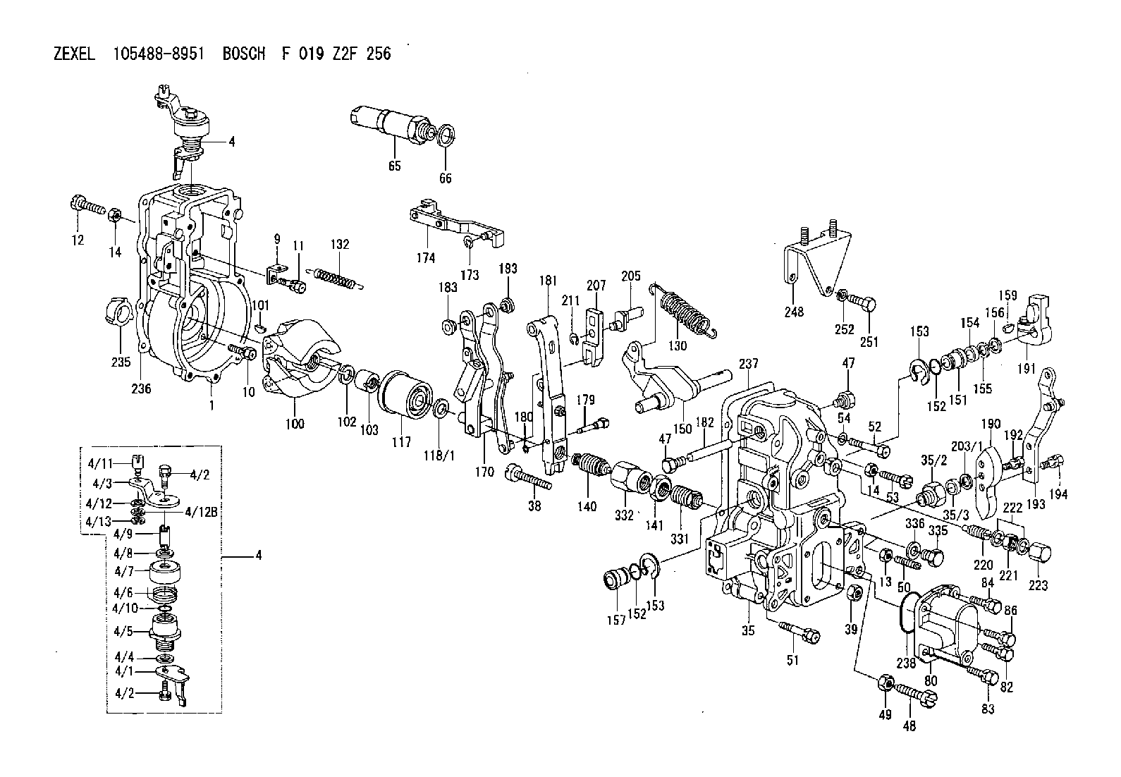
| 1. | [1] | 154004-1300 | GOVERNOR HOUSING |
| 4. | [1] | 154304-8221 | CONTROL LEVER |
| 4. | [1] | 154304-8221 | CONTROL LEVER |
| 4/1. | [1] | 154304-6200 | CONTROL LEVER |
| 4/2. | [2] | 154352-2000 | BLEEDER SCREW |
| 4/2. | [2] | 154352-2000 | BLEEDER SCREW |
| 4/3. | [1] | 154304-3300 | CONTROL LEVER |
| 4/4. | [1] | 029311-0230 | SHIM D18&10.3T0.5 |
| 4/5. | [1] | 154321-1500 | BUSHING |
| 4/6. | [1] | 154327-4100 | COILED SPRING |
| 4/7. | [1] | 154322-0100 | CAP |
| 4/8. | [1] | 029311-0220 | SHIM D18&10.3T0.2 |
| 4/9. | [1] | 154324-2700 | LEVER SHAFT |
| 4/10. | [1] | 029631-0030 | O-RING &9.8W2.3 |
| 4/11. | [1] | 154353-3701 | BEARING PIN |
| 4/12. | [1] | 014010-6140 | PLAIN WASHER D13&6.5T1 |
| 4/12B. | [0] | 029310-6040 | SHIM |
| 4/13. | [1] | 016010-0540 | LOCKING WASHER |
| 9. | [1] | 154353-5601 | PLATE |
| 10. | [4] | 020106-2040 | BLEEDER SCREW M6P1L20 |
| 11. | [4] | 020106-1840 | BLEEDER SCREW M6P1L18 |
| 12. | [1] | 154010-2900 | BLEEDER SCREW |
| 13. | [1] | 029240-6010 | UNION NUT M6P1.0H5* |
| 14. | [2] | 154011-0100 | HEXAGON NUT |
| 14. | [2] | 154011-0100 | HEXAGON NUT |
| 35. | [1] | 154513-3920 | GOVERNOR COVER |
| 35/2. | [1] | 154321-2000 | BUSHING |
| 35/3. | [1] | 029621-0080 | PACKING RING |
| 38. | [1] | 154031-3401 | FLAT-HEAD SCREW |
| 39. | [1] | 029201-0160 | UNION NUT |
| 47. | [2] | 154036-1800 | CAPSULE |
| 47. | [2] | 154036-1800 | CAPSULE |
| 48. | [1] | 154010-5500 | BLEEDER SCREW M10P1.25L42 |
| 49. | [1] | 154011-2100 | UNION NUT |
| 50. | [1] | 155615-2300 | FLAT-HEAD SCREW |
| 51. | [5] | 020106-4540 | BLEEDER SCREW M6P1.0L45 |
| 52. | [2] | 020306-6340 | BLEEDER SCREW |
| 53. | [1] | 154010-3100 | BLEEDER SCREW |
| 54. | [2] | 014110-6440 | LOCKING WASHER |
| 65. | [1] | 153043-5820 | STOPPING DEVICE |
| 66. | [1] | 026524-3040 | GASKET |
| 80. | [1] | 154063-4100 | COVER |
| 82. | [1] | 029020-6210 | BLEEDER SCREW |
| 83. | [1] | 029020-6210 | BLEEDER SCREW |
| 84. | [1] | 020006-1640 | BLEEDER SCREW M6P1L16 4T |
| 86. | [1] | 020006-1640 | BLEEDER SCREW M6P1L16 4T |
| 100. | [1] | 154100-9220 | FLYWEIGHT ASSEMBLY |
| 101. | [1] | 025803-1610 | WOODRUFF KEY |
| 102. | [1] | 029321-2020 | LOCKING WASHER |
| 103. | [1] | 139212-0000 | UNION NUT |
| 117. | [1] | 154123-2320 | SLIDING PIECE |
| 118/1. | [0] | 029311-0010 | SHIM D14&10.1T0.2 |
| 118/1. | [0] | 029311-0180 | SHIM D14&10.1T0.3 |
| 118/1. | [0] | 029311-0190 | SHIM D14&10.1T0.40 |
| 118/1. | [0] | 029311-0210 | SHIM D14&10.1T1 |
| 118/1. | [0] | 139410-0000 | SHIM D14.0&10.1T0.5 |
| 118/1. | [0] | 139410-0100 | SHIM D14.0&10.1T1.5 |
| 118/1. | [0] | 139410-3000 | SHIM D14&10.1T2.0 |
| 118/1. | [0] | 139410-3100 | SHIM D14&10.1T3.0 |
| 118/1. | [0] | 139410-3200 | SHIM D14&10.1T4.0 |
| 130. | [1] | 154150-8300 | GOVERNOR SPRING |
| 132. | [1] | 154154-0701 | COILED SPRING |
| 140. | [1] | 154183-1720 | HEADLESS SCREW |
| 141. | [1] | 139218-0100 | UNION NUT |
| 150. | [1] | 154200-5400 | SWIVELLING LEVER |
| 151. | [2] | 154200-5500 | BUSHING |
| 152. | [2] | 139700-0000 | O-RING |
| 152. | [2] | 139700-0000 | O-RING |
| 153. | [2] | 154354-3900 | LOCKING WASHER |
| 153. | [2] | 154354-3900 | LOCKING WASHER |
| 154. | [1] | 139610-0101 | PACKING RING |
| 155. | [1] | 139411-0100 | SHIM D22.0&12.0T0.40 |
| 156. | [0] | 139411-0200 | SHIM D18.0&12.0T0.10 |
| 156B. | [0] | 139411-0300 | SHIM D18.0&12.0T0.20 |
| 156C. | [0] | 139411-0400 | SHIM D18.0&12.0T0.30 |
| 157. | [1] | 139902-0000 | CAPSULE |
| 159. | [1] | 025803-1310 | WOODRUFF KEY |
| 170. | [1] | 154216-8420 | FORK LEVER |
| 173. | [1] | 016010-0540 | LOCKING WASHER |
| 174. | [1] | 154230-8120 | STRAP |
| 179. | [1] | 154238-0201 | BEARING PIN |
| 180. | [1] | 016010-0540 | LOCKING WASHER |
| 181. | [1] | 154236-6320 | TENSIONING LEVER |
| 182. | [1] | 154237-1200 | BEARING PIN |
| 183. | [2] | 154237-1300 | BUSHING |
| 183. | [2] | 154237-1300 | BUSHING |
| 190. | [1] | 154360-2800 | CONTROL LEVER |
| 191. | [1] | 154340-4320 | CONTROL LEVER |
| 192. | [1] | 020006-1670 | BLEEDER SCREW M6P1L16 7T |
| 193. | [1] | 154361-4420 | CONTROL LEVER |
| 194. | [2] | 020006-1240 | BLEEDER SCREW M6P1L12 4T |
| 203/1. | [0] | 029311-0640 | SHIM D26.0&10.2T0.95 |
| 203/1. | [0] | 029311-0650 | SHIM D26.0&10.2T0.20 |
| 203/1. | [0] | 029311-0660 | SHIM D26.0&10.2T0.25 |
| 203/1. | [0] | 029311-0670 | SHIM D26.0&10.2T0.30 |
| 203/1. | [0] | 029311-0680 | SHIM D26.0&10.2T0.35 |
| 203/1. | [0] | 029311-0690 | SHIM D26.0&10.2T0.40 |
| 203/1. | [0] | 029311-0700 | SHIM D26.0&10.2T0.50 |
| 203/1. | [0] | 139410-1400 | SHIM D26&10.2T0.7 |
| 203/1. | [0] | 139410-1500 | SHIM D26&10.2T0.9 |
| 203/1. | [0] | 139410-1600 | SHIM D26&10.2T0.8 |
| 203/1. | [0] | 139410-2700 | SHIM D26&10.2T0.6 |
| 205. | [1] | 154324-4100 | LEVER SHAFT |
| 207. | [1] | 154326-0300 | CONTROL LEVER |
| 211. | [1] | 016010-0840 | LOCKING WASHER |
| 220. | [1] | 154050-6220 | HEADLESS SCREW |
| 221. | [1] | 029201-2140 | UNION NUT |
| 222. | [2] | 026512-1540 | GASKET D15.4&12.2T1.50 |
| 223. | [1] | 154159-1200 | CAP NUT |
| 235. | [1] | 155412-5200 | IMPELLER WHEEL |
| 236. | [1] | 154371-5600 | GASKET |
| 237. | [1] | 154390-0200 | GASKET |
| 238. | [1] | 139700-0100 | O-RING |
| 248. | [1] | 154213-7021 | BRACKET |
| 251. | [1] | 010038-1440 | BLEEDER SCREW M8P1.25L14 |
| 252. | [1] | 014110-8440 | LOCKING WASHER |
| 331. | [1] | 154179-7420 | HEADLESS SCREW |
| 332. | [1] | 139218-0200 | UNION NUT |
| 335. | [1] | 154352-2600 | CAPSULE |
| 336. | [1] | 029331-6030 | GASKET |
Include in #1:
106871-3622
as GOVERNOR
Cross reference number
Zexel num
Bosch num
Firm num
Name
105488-8951
F 019 Z2F 256
223003100B HINO
GOVERNOR
* K
* K
Information:
Start By:
Do not let the tops of the nozzles turn while the fuel lines are loosened. The nozzles will be damaged if the top of the nozzle turns in the body. Defective fuel nozzles will damage the engine due to improper spray patterns.
a. remove fuel injection lines
Keep all parts clean from contaminants. Contaminants put into the system may cause rapid wear and shortened component life.
1. Remove clamp (1). 2. Install tool (A). Turn screw (2) out until the button on the screw almost makes contact with the inside of the nozzle puller. Tilt the tool approximately 45° and place it over the nozzle.3. Tilt the nozzle puller (A) up so the inside lip of the puller is under the stepped diameter of the nozzle.4. Turn screw (2) down until the button goes into the bolt hole for the nozzle hold down clamp.
Do not exceed a torque of 17 N m (13 lb ft) on the screw in tooling (A) to remove the nozzle. Added force can cause the stem of the nozzle to bend or break off.
5. Turn screw (2) to lift the nozzle out of its bore. If necessary, after the nozzle is loose in its bore, move it up and down to help loosen any carbon and make removal easier. 6. If the nozzle can not be removed with tooling (A), tooling (B) must be used. When tooling (B) is used, the nozzle normally can not be used again, and a new nozzle will need to be installed as a replacement.
Hold tool (B) so the center line of tool (B) is the same as the extended center line of fuel injection nozzle (2). This will prevent distortion of the fuel injection nozzle which can cause the nozzle to bend or break off.
7. Remove the protective cap and install tooling (B).8. Use the slide hammer to remove fuel injection nozzle (3).9. Remove the compression seal.10. For nozzles removed using tool (A), remove the carbon dam seal on the end of the nozzle. The following steps are for the installation of the fuel injection nozzles. Tool (C) must be modified by drilling it out to a diameter of 8.5 mm (.344 in) and to a depth of 1.5 mm (.060 in) before it can be used on the 8N7002 Fuel Injection Nozzle.11. Use tool (C) to install carbon dam seal (4).12. To clean the nozzles, see Special Instruction SEHS7292 for the use of tooling (D).13. Install new compression seal (5). 14. Use tool (E) to clean the bore for the fuel injection nozzle. 15. Install fuel injection nozzle (6).
Do not let the tops of the fuel nozzles turn when the fuel lines are tightened. The nozzles will be damaged if the top of the nozzle turns in the body.
End By:a. install fuel injection lines
Have questions with 105488-8951?
Group cross 105488-8951 ZEXEL
Hino
105488-8951
F 019 Z2F 256
223003100B
GOVERNOR