Information governor
BOSCH
F 019 Z2F 087
f019z2f087
ZEXEL
105488-8482
1054888482
Rating:
Scheme ###:
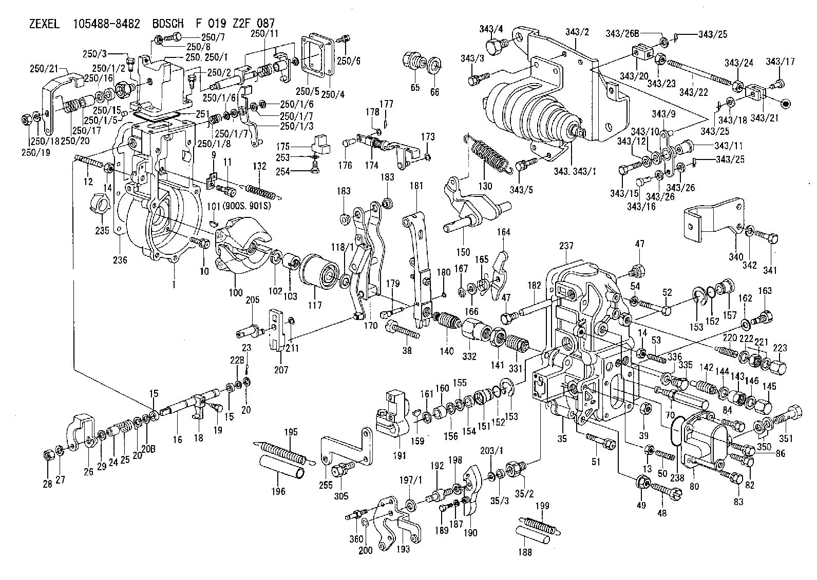
| 1. | [1] | 154004-4621 | GOVERNOR HOUSING |
| 9. | [1] | 154353-5601 | PLATE |
| 10. | [4] | 020106-2040 | BLEEDER SCREW M6P1L20 |
| 11. | [4] | 020106-1840 | BLEEDER SCREW M6P1L18 |
| 12. | [1] | 154010-0100 | FLAT-HEAD SCREW |
| 13. | [1] | 029240-6010 | UNION NUT M6P1.0H5* |
| 14. | [2] | 154011-0100 | HEXAGON NUT |
| 14. | [2] | 154011-0100 | HEXAGON NUT |
| 15. | [2] | 029620-8050 | PACKING RING |
| 15. | [2] | 029620-8050 | PACKING RING |
| 16. | [1] | 155004-3600 | LEVER SHAFT |
| 18. | [1] | 155003-2101 | CONTROL LEVER |
| 19. | [1] | 155006-0700 | BLEEDER SCREW |
| 20. | [1] | 139308-0900 | PLAIN WASHER D16&8T1 |
| 20. | [1] | 139308-0900 | PLAIN WASHER D16&8T1 |
| 20B. | [1] | 139308-1000 | PLAIN WASHER D16&8T1.5 |
| 20C. | [1] | 139408-1500 | SHIM |
| 22B. | [0] | 029310-8050 | SHIM D13.5&8T0.5 |
| 22B. | [7] | 139408-1500 | SHIM |
| 23. | [1] | 025520-1210 | SPLIT PIN |
| 24. | [1] | 154206-6300 | BUSHING |
| 25. | [1] | 154327-3600 | COILED SPRING |
| 26. | [1] | 154365-6500 | CONTROL LEVER |
| 27. | [1] | 014110-8440 | LOCKING WASHER |
| 28. | [1] | 013020-8040 | UNION NUT M8P1.25H7 |
| 29. | [1] | 139408-1400 | SHIM |
| 29B. | [0] | 139408-1400 | SHIM |
| 29C. | [0] | 139408-1500 | SHIM |
| 35. | [1] | 154514-0020 | GOVERNOR COVER |
| 35/2. | [1] | 154321-2000 | BUSHING |
| 35/3. | [1] | 029621-0080 | PACKING RING |
| 38. | [1] | 154031-3401 | FLAT-HEAD SCREW |
| 39. | [1] | 029201-0160 | UNION NUT |
| 47. | [2] | 154036-1800 | CAPSULE |
| 47. | [2] | 154036-1800 | CAPSULE |
| 48. | [1] | 154010-5500 | BLEEDER SCREW M10P1.25L42 |
| 49. | [1] | 154011-2100 | UNION NUT |
| 50. | [1] | 155615-2300 | FLAT-HEAD SCREW |
| 51. | [5] | 020106-4540 | BLEEDER SCREW M6P1.0L45 |
| 52. | [2] | 029010-6850 | BLEEDER SCREW |
| 53. | [1] | 154010-0100 | FLAT-HEAD SCREW |
| 54. | [2] | 014110-6440 | LOCKING WASHER |
| 65. | [1] | 153021-5000 | CAP |
| 66. | [1] | 026524-3040 | GASKET |
| 70. | [1] | 154055-1420 | HEADLESS SCREW |
| 80. | [1] | 154063-5620 | COVER |
| 82. | [1] | 020006-1640 | BLEEDER SCREW M6P1L16 4T |
| 83. | [1] | 029020-6210 | BLEEDER SCREW |
| 84. | [1] | 020006-1640 | BLEEDER SCREW M6P1L16 4T |
| 86. | [1] | 029020-6210 | BLEEDER SCREW |
| 100. | [1] | 154100-9320 | FLYWEIGHT ASSEMBLY |
| 101. | [1] | 025803-1310 | WOODRUFF KEY |
| 102. | [1] | 029321-2020 | LOCKING WASHER |
| 103. | [1] | 139212-0000 | UNION NUT |
| 117. | [1] | 154123-2320 | SLIDING PIECE |
| 118/1. | [0] | 029311-0010 | SHIM D14&10.1T0.2 |
| 118/1. | [0] | 029311-0180 | SHIM D14&10.1T0.3 |
| 118/1. | [0] | 029311-0190 | SHIM D14&10.1T0.40 |
| 118/1. | [0] | 029311-0210 | SHIM D14&10.1T1 |
| 118/1. | [0] | 139410-0000 | SHIM D14.0&10.1T0.5 |
| 118/1. | [0] | 139410-0100 | SHIM D14.0&10.1T1.5 |
| 118/1. | [0] | 139410-3000 | SHIM D14&10.1T2.0 |
| 118/1. | [0] | 139410-3100 | SHIM D14&10.1T3.0 |
| 118/1. | [0] | 139410-3200 | SHIM D14&10.1T4.0 |
| 130. | [1] | 154150-8400 | GOVERNOR SPRING |
| 132. | [1] | 154154-3700 | COILED SPRING |
| 140. | [1] | 154183-1020 | HEADLESS SCREW |
| 141. | [1] | 139218-0100 | UNION NUT |
| 142. | [1] | 154242-3320 | HEADLESS SCREW |
| 143. | [1] | 154242-3200 | UNION NUT |
| 144. | [1] | 026516-2040 | GASKET D19.9&16.2T1 |
| 145. | [1] | 154159-1800 | CAP NUT |
| 146. | [1] | 029331-6130 | GASKET |
| 150. | [1] | 154200-5801 | SWIVELLING LEVER |
| 151. | [1] | 154200-5501 | BUSHING |
| 152. | [2] | 139700-0000 | O-RING |
| 152. | [2] | 139700-0000 | O-RING |
| 153. | [2] | 154354-3900 | LOCKING WASHER |
| 153. | [2] | 154354-3900 | LOCKING WASHER |
| 154. | [1] | 139610-0101 | PACKING RING |
| 155. | [1] | 139411-0100 | SHIM D22.0&12.0T0.40 |
| 156. | [0] | 139411-0200 | SHIM D18.0&12.0T0.10 |
| 156B. | [0] | 139411-0300 | SHIM D18.0&12.0T0.20 |
| 156C. | [0] | 139411-0400 | SHIM D18.0&12.0T0.30 |
| 157. | [1] | 154204-3500 | BUSHING |
| 159. | [1] | 025803-1310 | WOODRUFF KEY |
| 160. | [1] | 154206-2300 | BUSHING |
| 161. | [0] | 154206-2400 | PLAIN WASHER D20.5&12.2T1 |
| 162. | [1] | 029331-6050 | GASKET |
| 163. | [1] | 154401-3201 | BLEEDER SCREW |
| 164. | [1] | 154243-0820 | CONTROL LEVER |
| 165. | [1] | 154327-6100 | COILED SPRING |
| 166. | [1] | 029310-8320 | SHIM D16.5&8T0.2 |
| 167. | [1] | 154356-3600 | LOCKING WASHER |
| 170. | [1] | 154216-6620 | FORK LEVER |
| 173. | [1] | 016010-0540 | LOCKING WASHER |
| 174. | [1] | 154234-0520 | STRAP |
| 175. | [1] | 154232-1821 | CONNECTOR |
| 176. | [1] | 159231-4900 | BEARING PIN |
| 177. | [1] | 155402-3800 | SAFETY PIN |
| 178. | [1] | 029310-5170 | SHIM D8&5.3T0.5 |
| 179. | [1] | 154238-0201 | BEARING PIN |
| 180. | [1] | 016010-0540 | LOCKING WASHER |
| 181. | [1] | 154236-8021 | TENSIONING LEVER |
| 182. | [1] | 154237-1200 | BEARING PIN |
| 183. | [2] | 154237-1300 | BUSHING |
| 183. | [2] | 154237-1300 | BUSHING |
| 187. | [1] | 014110-6440 | LOCKING WASHER |
| 188. | [1] | 154156-1500 | TUBE |
| 189. | [1] | 154357-6320 | BLEEDER SCREW |
| 190. | [1] | 154360-2700 | CONTROL LEVER |
| 191. | [1] | 154340-1920 | CONTROL LEVER |
| 192. | [1] | 154357-6401 | BLEEDER SCREW |
| 193. | [1] | 154363-9220 | CONTROL LEVER |
| 195. | [1] | 154317-1000 | COILED SPRING |
| 196. | [1] | 154156-1300 | TUBE |
| 197/1. | [0] | 029310-8610 | SHIM D10.5&8.5T0.1 |
| 197/1. | [0] | 029310-8620 | SHIM D10.5&8.5T0.15 |
| 197/1. | [0] | 029310-8630 | SHIM D10.5&8.5T0.2 |
| 197/1. | [0] | 029310-8650 | SHIM D10.5&8.5T0.5 |
| 198. | [1] | 014110-8440 | LOCKING WASHER |
| 199. | [1] | 154317-2000 | COILED SPRING |
| 200. | [1] | 016010-0740 | LOCKING WASHER |
| 203/1. | [0] | 029311-0640 | SHIM D26.0&10.2T0.95 |
| 203/1. | [0] | 029311-0650 | SHIM D26.0&10.2T0.20 |
| 203/1. | [0] | 029311-0660 | SHIM D26.0&10.2T0.25 |
| 203/1. | [0] | 029311-0670 | SHIM D26.0&10.2T0.30 |
| 203/1. | [0] | 029311-0680 | SHIM D26.0&10.2T0.35 |
| 203/1. | [0] | 029311-0690 | SHIM D26.0&10.2T0.40 |
| 203/1. | [0] | 029311-0700 | SHIM D26.0&10.2T0.50 |
| 203/1. | [0] | 139410-1400 | SHIM D26&10.2T0.7 |
| 203/1. | [0] | 139410-1500 | SHIM D26&10.2T0.9 |
| 203/1. | [0] | 139410-1600 | SHIM D26&10.2T0.8 |
| 203/1. | [0] | 139410-2700 | SHIM D26&10.2T0.6 |
| 205. | [1] | 154324-2900 | LEVER SHAFT |
| 207. | [1] | 154326-0300 | CONTROL LEVER |
| 211. | [1] | 016010-0840 | LOCKING WASHER |
| 220. | [1] | 154050-6820 | HEADLESS SCREW |
| 221. | [1] | 029201-2140 | UNION NUT |
| 222. | [2] | 139512-0000 | GASKET D17.2&12.2T1.0 |
| 223. | [1] | 154159-1200 | CAP NUT |
| 235. | [1] | 155412-5200 | IMPELLER WHEEL |
| 236. | [1] | 154371-5600 | GASKET |
| 237. | [1] | 154390-0200 | GASKET |
| 238. | [1] | 139700-0100 | O-RING |
| 250. | [1] | 154414-0020 | STARTING FUEL AIDS |
| 250/1. | [1] | 154414-1021 | GOVERNOR HOUSING |
| 250/1/2. | [1] | 154321-1800 | BUSHING |
| 250/1/3. | [1] | 154414-5020 | CONTROL LEVER |
| 250/1/5. | [1] | 154406-5100 | CAPSULE |
| 250/1/6. | [2] | 016010-0510 | LOCKING WASHER |
| 250/1/6. | [2] | 016010-0510 | LOCKING WASHER |
| 250/1/7. | [2] | 029310-5090 | SHIM D10&5.1T0.5 |
| 250/1/7. | [2] | 029310-5090 | SHIM D10&5.1T0.5 |
| 250/1/8. | [1] | 154414-2000 | COILED SPRING |
| 250/2. | [3] | 020106-1640 | BLEEDER SCREW M6P1.0L14 |
| 250/3. | [1] | 029020-6210 | BLEEDER SCREW |
| 250/4. | [1] | 154414-5300 | COVER |
| 250/5. | [1] | 154414-5400 | GASKET |
| 250/6. | [4] | 020105-1040 | BLEEDER SCREW M5P0.8L10 |
| 250/7. | [1] | 153141-1600 | BLEEDER SCREW |
| 250/8. | [1] | 029240-6010 | UNION NUT M6P1.0H5* |
| 250/11. | [1] | 154414-8320 | CONTROL LEVER |
| 250/15. | [1] | 029621-0080 | PACKING RING |
| 250/16. | [0] | 029311-0700 | SHIM D26.0&10.2T0.50 |
| 250/17. | [1] | 154414-5900 | BUSHING |
| 250/18. | [1] | 014110-8440 | LOCKING WASHER |
| 250/19. | [1] | 013010-8040 | UNION NUT M8P0.9H7 |
| 250/20. | [1] | 154414-2300 | COILED SPRING |
| 250/21. | [1] | 154414-5200 | CONTROL LEVER |
| 251. | [1] | 154358-2500 | SEAL RING |
| 253. | [1] | 029320-5020 | LOCKING WASHER |
| 254. | [1] | 010535-1040 | FLAT-HEAD SCREW M5P0.8L10 |
| 255. | [1] | 154357-6820 | BRACKET |
| 305. | [2] | 029010-5310 | BLEEDER SCREW |
| 331. | [1] | 154179-1620 | HEADLESS SCREW |
| 332. | [1] | 139218-0500 | UNION NUT |
| 335. | [1] | 154352-2600 | CAPSULE |
| 336. | [1] | 029331-6030 | GASKET |
| 340. | [1] | 154357-6621 | BRACKET |
| 341. | [2] | 010038-1440 | BLEEDER SCREW M8P1.25L14 |
| 342. | [2] | 014110-8440 | LOCKING WASHER |
| 343. | [1] | 154410-2021 | SOLENOID |
| 343/1. | [1] | 154410-1202 | SOLENOID |
| 343/2. | [1] | 154356-7320 | BRACKET |
| 343/3. | [4] | 020018-1670 | BLEEDER SCREW M8P1.25L16 7T |
| 343/4. | [2] | 159248-0200 | BLEEDER SCREW |
| 343/5. | [2] | 020006-1440 | BLEEDER SCREW M6P1L14 |
| 343/9. | [1] | 154357-7420 | BELL CRANK |
| 343/10. | [1] | 139308-0400 | PLAIN WASHER |
| 343/11. | [1] | 154354-4200 | BUSHING |
| 343/12. | [4] | 014010-8140 | PLAIN WASHER D18&8.5T1.6 |
| 343/15. | [1] | 020018-3570 | BLEEDER SCREW M8P1.25L35 7T |
| 343/16. | [1] | 154354-3100 | BEARING PIN |
| 343/17. | [1] | 154370-7900 | BEARING PIN |
| 343/18. | [2] | 014020-6140 | PLAIN WASHER |
| 343/20. | [1] | 154357-7200 | CLEVIS |
| 343/21. | [1] | 154357-7300 | CLEVIS |
| 343/22. | [1] | 154357-7600 | STRAP |
| 343/23. | [1] | 013020-6040 | UNION NUT M6P1H5 |
| 343/24. | [1] | 029200-6210 | UNION NUT |
| 343/25. | [3] | 155402-3800 | SAFETY PIN |
| 343/25. | [3] | 155402-3800 | SAFETY PIN |
| 343/25. | [3] | 155402-3800 | SAFETY PIN |
| 343/26. | [0] | 029310-6030 | SHIM D11.5&6.2T0.2 |
| 343/26. | [0] | 029310-6030 | SHIM D11.5&6.2T0.2 |
| 343/26B. | [0] | 014020-6140 | PLAIN WASHER |
| 350. | [2] | 139512-0000 | GASKET D17.2&12.2T1.0 |
| 351. | [1] | 139812-0100 | EYE BOLT |
| 360. | [1] | 154357-7000 | BEARING PIN |
| 900S. | [1] | 025803-1310 | WOODRUFF KEY |
| 901S. | [1] | 025803-1610 | WOODRUFF KEY |
Cross reference number
Zexel num
Bosch num
Firm num
Name
Information:
Start By:a. remove radiator
Keep all parts clean from contaminants. Contaminants put into the system may cause rapid wear and shortened component life.
1. Loosen bolt (4), bolt (5), and bolt (6). Remove belts (3).2. Remove bolts (2) and fan (1). 3. Remove bolt (7) and washer (8). Put enough spacers (10) on bolt (7) to get approximately 3.18 mm (.125 in) of clearance between washer (8) and vibration damper and pulley assembly (9). Install bolt (7), washer (8), and spacers (10).
If spacers (10) are not used, damage to the bolt and/or crankshaft can result when the vibration damper and pulley are removed from the crankshaft.
4. Install tool (A) as shown, and loosen vibration damper and pulley assembly (9).5. Remove tool (A), bolt (7), washer (8), spacers (10), and vibration damper and pulley assembly (9). 6. If necessary, remove bolts (11) and vibration damper (12). The following steps are to install the crankshaft vibration damper and pulley. Inspect the vibration damper housing for leakage or dents (damage housing). If either condition exists, a replacement of the vibration damper must be made.7. Install vibration damper (12) on pulley (13). Install bolts (11).8. Install vibration damper and pulley assembly (9) and install bolt (7), spacers (10) and washer (8).
The flat side of washer (8) must be installed toward vibration damper and pulley assembly (9).
9. Tighten bolt (7) to a torque of 284 to 340 N m (210 to 250 lb ft). Hit bolt (7) with a hammer and retighten to a torque of 284 to 340 N m (210 to 250 lb ft).10. Position belts (3). Tighten bolts (4), (5), and (6). Use a belt tension gauge and make an adjustment of the belts. Measure the belt farthest from the engine. Tighten new belts until the gauge indication is 534 22 N (120 5 lb ft). Operate the engine at high idle for a minimum of 30 minutes after installing radiator and guards. Make another adjustment of the belt tension. The correct gauge indication for a used belt is 400 44 N (90 10 lb.). Tighten bolt (4), bolt (5), and bolt (6).11. Install fan (1) and bolt (2).End By:a. install radiator
Perform Scheduled Oil Sampling on oil wetted compartments after performing service work to check for contaminants left in the system following repair. Contaminants put into the system may cause rapid wear and shortened component life.