Information governor
BOSCH
F 019 Z1E 319
f019z1e319
ZEXEL
105488-7850
1054887850
HINO
223002800A
223002800a
Rating:
Scheme ###:
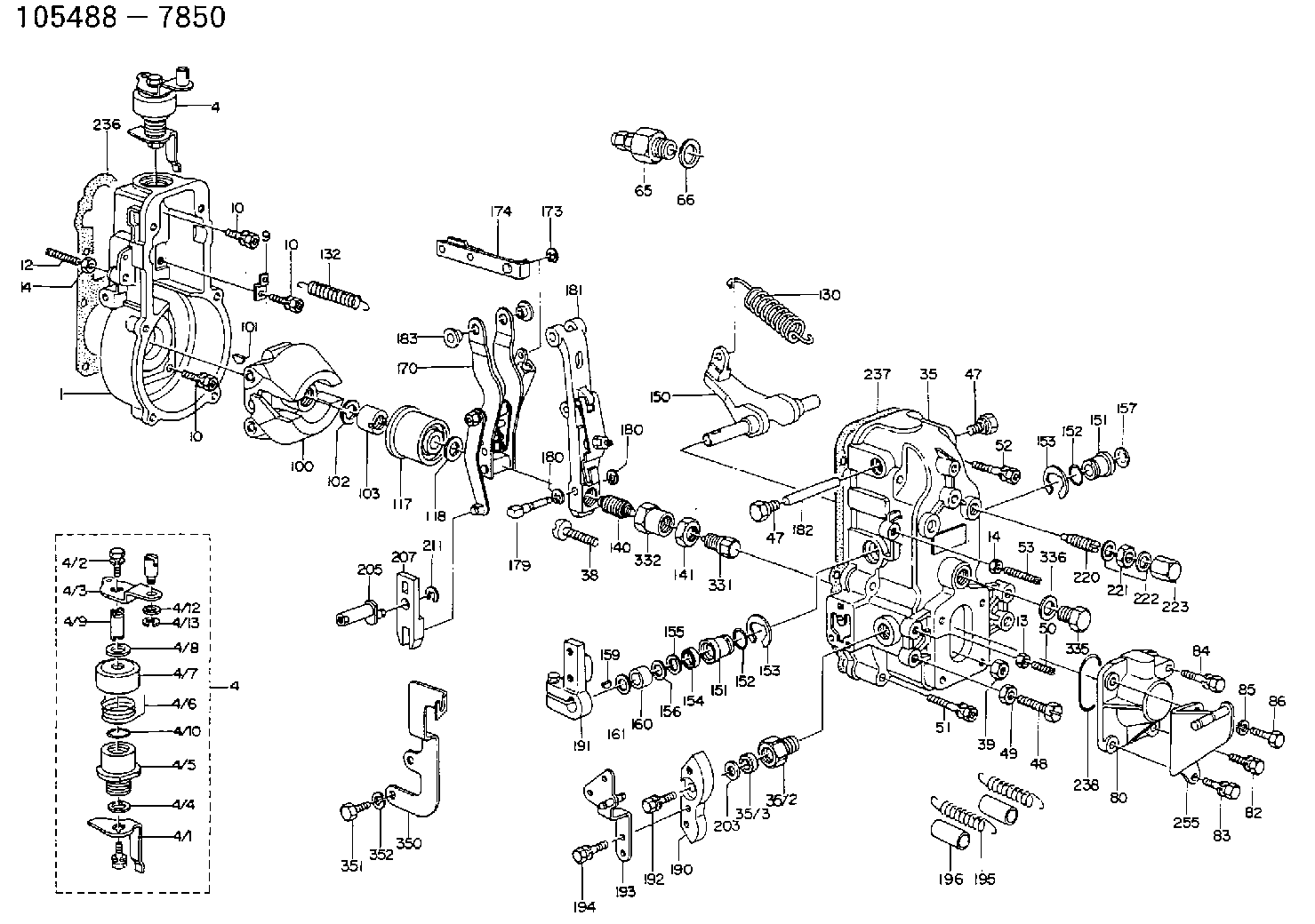
| 1. | [1] | 154000-9100 | GOVERNOR HOUSING |
| 4. | [1] | 154304-8221 | CONTROL LEVER |
| 4. | [1] | 154304-8221 | CONTROL LEVER |
| 4/1. | [1] | 154304-6200 | CONTROL LEVER |
| 4/2. | [2] | 154352-2000 | BLEEDER SCREW |
| 4/3. | [1] | 154304-3300 | CONTROL LEVER |
| 4/4. | [1] | 029311-0230 | SHIM D18&10.3T0.5 |
| 4/5. | [1] | 154321-1500 | BUSHING |
| 4/6. | [1] | 154327-4100 | COILED SPRING |
| 4/7. | [1] | 154322-0100 | CAP |
| 4/8. | [1] | 029311-0220 | SHIM D18&10.3T0.2 |
| 4/9. | [1] | 154324-2700 | LEVER SHAFT |
| 4/10. | [1] | 029631-0030 | O-RING &9.8W2.3 |
| 4/11. | [1] | 154353-3701 | BEARING PIN |
| 4/12. | [1] | 014010-6140 | PLAIN WASHER D13&6.5T1 |
| 4/12B. | [0] | 029310-6040 | SHIM |
| 4/13. | [1] | 016010-0540 | LOCKING WASHER |
| 9. | [1] | 154350-6000 | PLATE |
| 10. | [8] | 020106-2040 | BLEEDER SCREW M6P1L20 |
| 10. | [8] | 020106-2040 | BLEEDER SCREW M6P1L20 |
| 10. | [8] | 020106-2040 | BLEEDER SCREW M6P1L20 |
| 12. | [1] | 154010-1100 | FLAT-HEAD SCREW |
| 13. | [1] | 029240-6010 | UNION NUT M6P1.0H5* |
| 14. | [2] | 154011-0100 | HEXAGON NUT |
| 14. | [2] | 154011-0100 | HEXAGON NUT |
| 35. | [1] | 154513-6020 | GOVERNOR COVER |
| 35/2. | [1] | 154321-1800 | BUSHING |
| 35/3. | [1] | 029621-0080 | PACKING RING |
| 38. | [1] | 154031-3500 | FLAT-HEAD SCREW |
| 39. | [1] | 154011-1600 | UNION NUT |
| 47. | [1] | 154036-0300 | CAPSULE |
| 47. | [1] | 154036-0300 | CAPSULE |
| 48. | [1] | 154010-5500 | BLEEDER SCREW M10P1.25L42 |
| 49. | [1] | 154011-2100 | UNION NUT |
| 50. | [1] | 155615-1100 | FLAT-HEAD SCREW M6P1.0L37 |
| 51. | [4] | 020106-3840 | BLEEDER SCREW |
| 52. | [2] | 020106-5040 | BLEEDER SCREW |
| 53. | [1] | 154010-1100 | FLAT-HEAD SCREW |
| 65. | [1] | 153021-2220 | STOPPING DEVICE |
| 66. | [1] | 026524-3040 | GASKET |
| 80. | [1] | 154060-7300 | COVER |
| 82. | [1] | 029020-6210 | BLEEDER SCREW |
| 83. | [1] | 029020-6240 | BLEEDER SCREW |
| 84. | [1] | 010006-3840 | BLEEDER SCREW |
| 85. | [1] | 014110-6440 | LOCKING WASHER |
| 86. | [1] | 020006-1840 | BLEEDER SCREW M6P1L18 |
| 100. | [1] | 154100-9520 | FLYWEIGHT ASSEMBLY |
| 101. | [1] | 025803-1310 | WOODRUFF KEY |
| 102. | [1] | 029321-2020 | LOCKING WASHER |
| 103. | [1] | 029231-2030 | UNION NUT |
| 117. | [1] | 154123-2320 | SLIDING PIECE |
| 118/1. | [0] | 029311-0010 | SHIM D14&10.1T0.2 |
| 118/1. | [0] | 029311-0180 | SHIM D14&10.1T0.3 |
| 118/1. | [0] | 029311-0190 | SHIM D14&10.1T0.40 |
| 118/1. | [0] | 029311-0210 | SHIM D14&10.1T1 |
| 118/1. | [0] | 139410-0000 | SHIM D14.0&10.1T0.5 |
| 118/1. | [0] | 139410-0100 | SHIM D14.0&10.1T1.5 |
| 118/1. | [0] | 139410-3000 | SHIM D14&10.1T2.0 |
| 118/1. | [0] | 139410-3100 | SHIM D14&10.1T3.0 |
| 118/1. | [0] | 139410-3200 | SHIM D14&10.1T4.0 |
| 130. | [1] | 154150-6200 | GOVERNOR SPRING |
| 132. | [1] | 154154-4000 | COILED SPRING |
| 140. | [1] | 154178-2820 | HEADLESS SCREW |
| 141. | [1] | 029201-6220 | UNION NUT |
| 150. | [1] | 154200-3701 | SWIVELLING LEVER |
| 151. | [1] | 154204-2001 | BUSHING |
| 151. | [1] | 154204-2001 | BUSHING |
| 152. | [2] | 029631-8020 | O-RING |
| 152. | [2] | 029631-8020 | O-RING |
| 153. | [2] | 154354-3900 | LOCKING WASHER |
| 153. | [2] | 154354-3900 | LOCKING WASHER |
| 154. | [1] | 139611-0000 | PACKING RING |
| 155. | [1] | 139411-0000 | SHIM |
| 156/1. | [0] | 029311-1110 | SHIM D17&11T0.1 |
| 156/1. | [0] | 029311-1120 | SHIM D17&11T0.2 |
| 156/1. | [0] | 029311-1130 | SHIM D17&11T0.3 |
| 157. | [1] | 154204-3400 | BUSHING |
| 159. | [1] | 025803-1310 | WOODRUFF KEY |
| 170. | [1] | 154216-4120 | FORK LEVER |
| 173. | [1] | 016010-0540 | LOCKING WASHER |
| 174. | [1] | 154230-4920 | STRAP |
| 179. | [1] | 154238-0301 | BEARING PIN |
| 180. | [1] | 016010-0540 | LOCKING WASHER |
| 180. | [1] | 016010-0540 | LOCKING WASHER |
| 181. | [1] | 154236-7220 | TENSIONING LEVER |
| 182. | [1] | 154237-0900 | BEARING PIN |
| 183. | [2] | 154237-0600 | BUSHING |
| 190. | [1] | 154360-2700 | CONTROL LEVER |
| 191. | [1] | 154340-2220 | CONTROL LEVER |
| 192. | [1] | 020006-1670 | BLEEDER SCREW M6P1L16 7T |
| 193. | [1] | 154361-7020 | CONTROL LEVER |
| 194. | [2] | 020006-1240 | BLEEDER SCREW M6P1L12 4T |
| 195. | [2] | 154314-8900 | COILED SPRING |
| 196. | [2] | 154156-0900 | TUBE |
| 203/1. | [0] | 029311-0640 | SHIM D26.0&10.2T0.95 |
| 203/1. | [0] | 029311-0650 | SHIM D26.0&10.2T0.20 |
| 203/1. | [0] | 029311-0660 | SHIM D26.0&10.2T0.25 |
| 203/1. | [0] | 029311-0670 | SHIM D26.0&10.2T0.30 |
| 203/1. | [0] | 029311-0680 | SHIM D26.0&10.2T0.35 |
| 203/1. | [0] | 029311-0690 | SHIM D26.0&10.2T0.40 |
| 203/1. | [0] | 029311-0700 | SHIM D26.0&10.2T0.50 |
| 203/1. | [0] | 139410-1400 | SHIM D26&10.2T0.7 |
| 203/1. | [0] | 139410-1500 | SHIM D26&10.2T0.9 |
| 203/1. | [0] | 139410-1600 | SHIM D26&10.2T0.8 |
| 203/1. | [0] | 139410-2700 | SHIM D26&10.2T0.6 |
| 205. | [1] | 154324-3000 | LEVER SHAFT |
| 207. | [1] | 154326-6223 | CONTROL LEVER |
| 211. | [1] | 016010-0840 | LOCKING WASHER |
| 220. | [1] | 154050-3520 | HEADLESS SCREW |
| 221. | [1] | 029201-2140 | UNION NUT |
| 222. | [2] | 026512-1540 | GASKET D15.4&12.2T1.50 |
| 223. | [1] | 154159-1200 | CAP NUT |
| 236. | [1] | 154371-5600 | GASKET |
| 237. | [1] | 154390-0300 | GASKET |
| 238. | [1] | 029635-2020 | O-RING |
| 255. | [1] | 154213-7220 | BRACKET |
| 331. | [1] | 154179-3020 | HEADLESS SCREW |
| 332. | [1] | 029201-6010 | UNION NUT |
| 335. | [1] | 154352-2600 | CAPSULE |
| 336. | [1] | 029331-6030 | GASKET |
| 350. | [1] | 154354-3500 | BRACKET |
| 351. | [2] | 010010-1240 | BLEEDER SCREW M10P1.5L12 4T |
| 352. | [2] | 014111-0440 | LOCKING WASHER |
| 900S. | [1] | 025803-1310 | WOODRUFF KEY |
| 901S. | [1] | 025803-1610 | WOODRUFF KEY |
Include in #1:
106671-3384
as GOVERNOR
Cross reference number
Zexel num
Bosch num
Firm num
Name
Information:
2. Turn the crankshaft until two pistons are at bottom center.3. Remove nuts (1) and the bearing caps. Push the rods and pistons up until the rings are out of the cylinder liners. 4. Remove pistons (2) and connecting rods from the cylinder liners.5. Do Steps 1 through 4 for the remainder of the pistons and connecting rods.Install Pistons And Connecting Rod Assemblies
1. Put clean engine oil on piston rings, connecting rod bearings and cylinder liners. Some engines use pistons which have the word "FRONT" stamped on the crown of the piston. These pistons also have a green color code on the bottom surface of the side relief directly under the word "FRONT". Make sure the word "FRONT" and the color code are toward the front of the engine when the piston is installed.2. Use tool (A), and install piston (1) and the connecting rod in the cylinder liner. Be sure the number on the tab groove side of the connecting rod is on the opposite side from the camshaft. Also, be sure the word "FRONT" on the crown of the piston is toward the front of the engine. 3. Install the bearing cap on the connecting rod with the number on the side of the bearing cap on the same side and same number as on the connecting rod.4. Put 2P2506 Thread Lubricant on the threads of the bolts. Install the nuts, and tighten them to a torque of 80 8 N m (60 6 lb.ft.). Put a mark on the nuts and cap, and tighten the nuts an extra 120°.5. Do Steps 1 through 4 for the remainder of the pistons.END BY:a. install oil pumpb. install cylinder head assemblyDisassemble And Assemble Pistons And Connecting Rod Assemblies
START BY:a. remove pistons and connecting rod assemblies 1. Remove bearings (3) from the connecting rod and connecting rod cap.2. Remove retainer ring (1) with tool (A).3. Remove pin (2) and connecting rod (4) from the piston. 4. Remove piston rings (5) from the piston with tool (B). Clean the piston ring grooves on the pistons with an acceptable ring groove cleaning tool. See Use Of Piston Pin Bearing Removal And Installation Tools, Special Instructions, Form No. SMHS7295.5. Heat connecting rod (4) in an oven to a temperature of 177° to 260°C (350° to 500°F). Never use a direct flame to heat a connecting rod. 6. Put connecting rod (4) in position on the base plate of tooling (C). Put a new rod pin bearing (6) on the adapter part of tooling (C). The old bearing is pushed out by tooling (C) as the new bearing is installed.7. Use tooling (C) to push the new bearing into the connecting rod until the push adapter of tooling (C) makes full contact with the connecting rod surface.8. Use a pin boring machine to make the rod pin bearing the correct size. The bore in the new rod pin bearing must be 50.830 0.008 mm (2.0012 .0003 in.).9. Check the