Information governor
BOSCH
F 019 Z1E 643
f019z1e643
ZEXEL
105488-2120
1054882120
Rating:
Scheme ###:
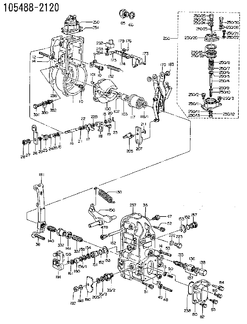
| 1. | [1] | 154000-9321 | GOVERNOR HOUSING |
| 9. | [1] | 154350-6000 | PLATE |
| 10. | [8] | 020106-2040 | BLEEDER SCREW M6P1L20 |
| 10. | [8] | 020106-2040 | BLEEDER SCREW M6P1L20 |
| 12. | [1] | 154010-0100 | FLAT-HEAD SCREW |
| 13. | [1] | 029240-6010 | UNION NUT M6P1.0H5* |
| 14. | [2] | 154011-0100 | HEXAGON NUT |
| 14. | [2] | 154011-0100 | HEXAGON NUT |
| 15. | [2] | 029620-8050 | PACKING RING |
| 15. | [2] | 029620-8050 | PACKING RING |
| 16. | [1] | 155004-3200 | LEVER SHAFT |
| 17. | [1] | 154408-1520 | CONTROL LEVER |
| 18. | [1] | 155003-1920 | CONTROL LEVER |
| 19. | [1] | 155006-0700 | BLEEDER SCREW |
| 20. | [0] | 139308-0900 | PLAIN WASHER D16&8T1 |
| 20. | [0] | 139308-0900 | PLAIN WASHER D16&8T1 |
| 20B. | [0] | 139308-1000 | PLAIN WASHER D16&8T1.5 |
| 21. | [1] | 016010-0740 | LOCKING WASHER |
| 22. | [0] | 029310-8040 | SHIM D13.5&8T0.2 |
| 22B. | [0] | 029310-8050 | SHIM D13.5&8T0.5 |
| 23. | [1] | 025520-1210 | SPLIT PIN |
| 24. | [1] | 154206-2000 | BUSHING |
| 25. | [1] | 154327-3600 | COILED SPRING |
| 26. | [1] | 154304-8500 | CONTROL LEVER |
| 27. | [1] | 014110-8440 | LOCKING WASHER |
| 28. | [1] | 013020-8040 | UNION NUT M8P1.25H7 |
| 29. | [1] | 139408-1400 | SHIM |
| 29B. | [0] | 139408-1400 | SHIM |
| 29C. | [0] | 139408-1500 | SHIM |
| 35. | [1] | 154513-5220 | GOVERNOR COVER |
| 35/2. | [1] | 154321-1800 | BUSHING |
| 35/3. | [1] | 029621-0080 | PACKING RING |
| 38. | [1] | 154031-3200 | FLAT-HEAD SCREW |
| 39. | [1] | 154011-1600 | UNION NUT |
| 47. | [1] | 154036-1200 | CAPSULE |
| 47B. | [1] | 154036-0300 | CAPSULE |
| 48. | [1] | 154010-0300 | FLAT-HEAD SCREW |
| 49. | [1] | 029240-8000 | UNION NUT |
| 50. | [1] | 155615-1100 | FLAT-HEAD SCREW M6P1.0L37 |
| 51. | [4] | 020106-3840 | BLEEDER SCREW |
| 52. | [2] | 020106-5040 | BLEEDER SCREW |
| 53. | [1] | 154010-0100 | FLAT-HEAD SCREW |
| 65. | [1] | 153021-4820 | STOPPING DEVICE |
| 66. | [1] | 026524-3040 | GASKET |
| 80. | [1] | 154060-7900 | COVER |
| 82. | [1] | 020006-1640 | BLEEDER SCREW M6P1L16 4T |
| 83. | [1] | 029020-6210 | BLEEDER SCREW |
| 84. | [1] | 029000-6800 | BLEEDER SCREW |
| 86. | [1] | 029020-6210 | BLEEDER SCREW |
| 100. | [1] | 154100-5020 | FLYWEIGHT ASSEMBLY |
| 101. | [1] | 025803-1610 | WOODRUFF KEY |
| 102. | [1] | 029321-2020 | LOCKING WASHER |
| 103. | [1] | 029231-2030 | UNION NUT |
| 117. | [1] | 154123-2320 | SLIDING PIECE |
| 118/1. | [0] | 029311-0010 | SHIM D14&10.1T0.2 |
| 118/1. | [0] | 029311-0180 | SHIM D14&10.1T0.3 |
| 118/1. | [0] | 029311-0190 | SHIM D14&10.1T0.40 |
| 118/1. | [0] | 029311-0210 | SHIM D14&10.1T1 |
| 118/1. | [0] | 139410-0000 | SHIM D14.0&10.1T0.5 |
| 118/1. | [0] | 139410-0100 | SHIM D14.0&10.1T1.5 |
| 118/1. | [0] | 139410-3000 | SHIM D14&10.1T2.0 |
| 118/1. | [0] | 139410-3100 | SHIM D14&10.1T3.0 |
| 118/1. | [0] | 139410-3200 | SHIM D14&10.1T4.0 |
| 130. | [1] | 154150-6200 | GOVERNOR SPRING |
| 132. | [1] | 154154-2601 | COILED SPRING |
| 135. | [1] | 154158-1820 | HEADLESS SCREW |
| 136. | [1] | 029201-2140 | UNION NUT |
| 137. | [2] | 026512-1540 | GASKET D15.4&12.2T1.50 |
| 138. | [1] | 154159-1200 | CAP NUT |
| 140. | [1] | 154180-2520 | HEADLESS SCREW |
| 141. | [1] | 029201-6010 | UNION NUT |
| 150. | [1] | 154200-3701 | SWIVELLING LEVER |
| 151. | [1] | 154204-2001 | BUSHING |
| 152. | [2] | 029631-8020 | O-RING |
| 152. | [2] | 029631-8020 | O-RING |
| 153. | [2] | 154354-3900 | LOCKING WASHER |
| 153. | [2] | 154354-3900 | LOCKING WASHER |
| 154. | [1] | 139611-0000 | PACKING RING |
| 155. | [1] | 139411-0000 | SHIM |
| 156/1. | [0] | 029311-1110 | SHIM D17&11T0.1 |
| 156/1. | [0] | 029311-1120 | SHIM D17&11T0.2 |
| 156/1. | [0] | 029311-1130 | SHIM D17&11T0.3 |
| 157. | [1] | 154204-3400 | BUSHING |
| 159. | [1] | 025803-1310 | WOODRUFF KEY |
| 160. | [1] | 154206-0900 | BUSHING |
| 161. | [0] | 154206-0200 | PLAIN WASHER D19.5&11.2T1.0 |
| 170. | [1] | 154211-7220 | FORK LEVER |
| 173. | [1] | 016010-0540 | LOCKING WASHER |
| 174. | [1] | 154234-2920 | STRAP |
| 175. | [1] | 159231-4900 | BEARING PIN |
| 176. | [1] | 155402-3800 | SAFETY PIN |
| 179. | [1] | 029310-5170 | SHIM D8&5.3T0.5 |
| 181. | [1] | 154236-4520 | TENSIONING LEVER |
| 182. | [1] | 154237-0400 | BEARING PIN |
| 183. | [2] | 154237-0600 | BUSHING |
| 190. | [1] | 154361-4900 | CONTROL LEVER |
| 191. | [1] | 154340-0320 | CONTROL LEVER |
| 192. | [1] | 013020-8040 | UNION NUT M8P1.25H7 |
| 198. | [1] | 014110-8440 | LOCKING WASHER |
| 203/1. | [0] | 029311-0640 | SHIM D26.0&10.2T0.95 |
| 203/1. | [0] | 029311-0650 | SHIM D26.0&10.2T0.20 |
| 203/1. | [0] | 029311-0660 | SHIM D26.0&10.2T0.25 |
| 203/1. | [0] | 029311-0670 | SHIM D26.0&10.2T0.30 |
| 203/1. | [0] | 029311-0680 | SHIM D26.0&10.2T0.35 |
| 203/1. | [0] | 029311-0690 | SHIM D26.0&10.2T0.40 |
| 203/1. | [0] | 029311-0700 | SHIM D26.0&10.2T0.50 |
| 203/1. | [0] | 139410-1400 | SHIM D26&10.2T0.7 |
| 203/1. | [0] | 139410-1500 | SHIM D26&10.2T0.9 |
| 203/1. | [0] | 139410-1600 | SHIM D26&10.2T0.8 |
| 203/1. | [0] | 139410-2700 | SHIM D26&10.2T0.6 |
| 205. | [1] | 154324-1200 | LEVER SHAFT |
| 207. | [1] | 154326-0300 | CONTROL LEVER |
| 211. | [1] | 016010-0840 | LOCKING WASHER |
| 222. | [1] | 026512-1540 | GASKET D15.4&12.2T1.50 |
| 223. | [1] | 029111-2040 | CAPSULE |
| 236. | [1] | 154371-5600 | GASKET |
| 237. | [1] | 154390-0300 | GASKET |
| 238. | [1] | 029635-2020 | O-RING |
| 250. | [1] | 154421-0220 | MANIFOLD-PRESSURE COMP. |
| 250. | [1] | 154421-0220 | MANIFOLD-PRESSURE COMP. |
| 250/1. | [1] | 154408-6220 | DIAPHRAGM HOUSING |
| 250/2. | [3] | 020106-1640 | BLEEDER SCREW M6P1.0L14 |
| 250/3. | [1] | 029020-6210 | BLEEDER SCREW |
| 250/4. | [1] | 154400-5101 | STOP PIN |
| 250/5. | [1] | 153400-0900 | SLOTTED WASHER |
| 250/6. | [1] | 016010-0740 | LOCKING WASHER |
| 250/7. | [0] | 029312-0180 | SHIM D25.5&20T0.5 |
| 250/7B. | [0] | 029312-0210 | SHIM D25.5&20T0.2 |
| 250/8. | [1] | 154411-2000 | COILED SPRING |
| 250/9. | [0] | 154355-3900 | SHIM D18&12.5T0.10 |
| 250/9B. | [0] | 154355-4000 | SHIM D18&12.5T0.20 |
| 250/9C. | [0] | 154355-4100 | SHIM D18&12.5T0.30 |
| 250/10. | [1] | 154411-2200 | COILED SPRING |
| 250/11. | [1] | 153400-0800 | SPRING SEAT |
| 250/12. | [1] | 014110-5440 | LOCKING WASHER |
| 250/13. | [1] | 013030-5240 | UNION NUT M5P0.8H3.2 |
| 250/15. | [1] | 154400-7720 | DIAPHRAGM |
| 250/20. | [1] | 154404-5000 | COVER |
| 250/21. | [3] | 029010-6310 | BLEEDER SCREW |
| 250/22. | [3] | 014110-6440 | LOCKING WASHER |
| 250/23. | [1] | 154404-1100 | FLAT-HEAD SCREW |
| 250/24. | [1] | 013030-6040 | UNION NUT M6P1H3.6 |
| 250/25. | [1] | 154035-1900 | CAP NUT |
| 250/28. | [2] | 026510-1340 | GASKET D13.4&10.2T1 |
| 250/30. | [1] | 029731-0180 | EYE BOLT |
| 250/33. | [2] | 154413-2600 | GASKET |
| 250/34. | [2] | 026506-1040 | GASKET D9.9&6.2T1 |
| 251. | [1] | 154390-2000 | GASKET |
| 252. | [1] | 154232-1220 | PLATE |
| 253. | [1] | 029320-5020 | LOCKING WASHER |
| 254. | [1] | 010535-1040 | FLAT-HEAD SCREW M5P0.8L10 |
| 331. | [1] | 154179-1420 | HEADLESS SCREW |
| 332. | [1] | 029201-6130 | UNION NUT |
| 350. | [2] | 026506-1040 | GASKET D9.9&6.2T1 |
| 351. | [1] | 029730-6030 | EYE BOLT |
| 352. | [1] | 155012-0700 | ADAPTOR |
Include in #1:
106971-5120
as GOVERNOR
Cross reference number
Zexel num
Bosch num
Firm num
Name
Information:
REMOVING CONNECTING ROD BEARING CAP4. Push the piston and connecting rod upward until the piston rings clear the cylinder block. Remove the piston and connecting rod from the cylinder block.
REMOVING PISTON
Do not allow the connecting rods to hit the bottom edge of the cylinder bores or crankshaft journals when removing or installing. Check the lower portion of the bores for burrs or scratches. Use crocus cloth to remove any burrs or scratches from bottom edge of the bores.
5. Keep the connecting rod bearing cap with its respective connecting rod and piston.6. Repeat Steps 2 through 5 for the remaining pistons.Install Pistons
1. Rotate the crankshaft to position bearing journal of the piston to be installed.2. Lubricate the crankshaft bearing journal, bore in cylinder block, piston, rings, and connecting rod bearings with clean engine oil (SAE 30).3. Install a 1Y7426 Ring Compressor (3), or the 4S9450 Compressor (1) and the 4S9446 Clamp (2) from the 4S9458 Teflon Seal Tool Group, on the piston to compress the rings. Install the piston and connecting rod in cylinder bore with piston crater toward vee of engine. Guide the lower end of connecting rod over the crankshaft journal to prevent damage to the crankshaft.
INSTALLING PISTON
1. 4S9450 Compressor. 2. 4S9446 Clamp.
INSTALLING PISTON ALTERNATE METHOD
3. 1Y7426 Ring Compressor.4. Install the connecting rod cap to connecting rod so numbers correspond and both numbers appear on the same side. Lubricate bolt threads, seating faces of cap and nuts, install the retaining nuts and tighten to 30 3 lb. ft. (4.1 0.4 mkg). Mark cap and nut with matching marks. Tighten additional from mark 60° 5°.5. Repeat Steps 1 thru 4 for the remaining pistons.Disassemble Piston
PISTON ASSEMBLY1. Use ring expander (1) to remove rings.
REMOVING RINGS
1. 5F9059 Ring Expander.2. Remove snap ring (5) and push piston pin (2) out of piston (4) and connecting rod (3).
PISTON DISASSEMBLED
2. Piston pin. 3. Connecting rod. 4. Piston. 5. Snap ring.Assemble Piston
1. Install connecting rod into piston with boss on rod on same side as crater in piston crown.
CONNECTING ROD AND PISTON
CONNECTING ROD AND PISTON Installation of connecting rods WITHOUT BOSS on rod; Install connecting rod into piston with cylinder identification number (as marked on the lower end of the rod and on the cap) 180° opposite the crater in piston crown.2. Install piston pin and snap rings.3. Use the 8S2304 Piston Ring Groove Cleaner to clean the piston ring grooves before installing piston rings.4. Install oil ring spring (6) before installing oil ring.
8S2304 RING GROOVE CLEANER
INSTALLING OIL RING SPRING
6. Oil ring spring.5. Use a 5F9059 Ring Expander to install piston rings. Install compression ring with side marked "TOP" toward top of piston. Install oil ring with gap 180° from oil ring spring joint and approximately 120° from compression ring gap.