Information governor
BOSCH
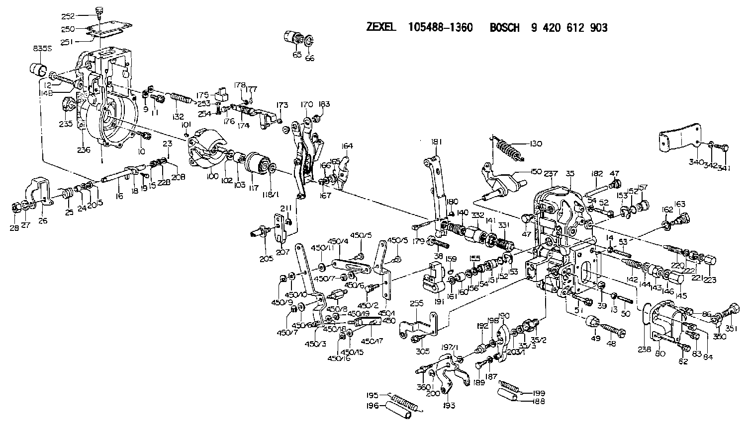
9 420 612 903
9420612903
ZEXEL
105488-1360
1054881360
Rating:
Scheme ###:
| 1. | [1] | 154004-4621 | GOVERNOR HOUSING |
| 9. | [1] | 154353-5601 | PLATE |
| 10. | [4] | 020106-2040 | BLEEDER SCREW M6P1L20 |
| 11. | [4] | 020106-1840 | BLEEDER SCREW M6P1L18 |
| 12. | [1] | 154010-7200 | BLEEDER SCREW M8P1.25L62 |
| 13. | [1] | 013020-6040 | UNION NUT M6P1H5 |
| 14. | [1] | 154011-0100 | HEXAGON NUT |
| 14B. | [1] | 154011-2300 | UNION NUT |
| 15. | [2] | 139608-0100 | PACKING RING |
| 15. | [2] | 139608-0100 | PACKING RING |
| 16. | [1] | 155004-3600 | LEVER SHAFT |
| 18. | [1] | 155003-2101 | CONTROL LEVER |
| 19. | [1] | 155006-0100 | BLEEDER SCREW |
| 20. | [1] | 139308-0900 | PLAIN WASHER D16&8T1 |
| 20B. | [1] | 139308-1000 | PLAIN WASHER D16&8T1.5 |
| 22B. | [0] | 029310-8050 | SHIM D13.5&8T0.5 |
| 23. | [1] | 025520-1210 | SPLIT PIN |
| 24. | [1] | 154206-2000 | BUSHING |
| 25. | [1] | 154327-3600 | COILED SPRING |
| 26. | [1] | 154365-6500 | CONTROL LEVER |
| 27. | [1] | 014110-8440 | LOCKING WASHER |
| 28. | [1] | 013020-8040 | UNION NUT M8P1.25H7 |
| 35. | [1] | 154515-2320 | GOVERNOR COVER |
| 35/2. | [1] | 154321-2000 | BUSHING |
| 35/3. | [1] | 139610-0600 | PACKING RING |
| 38. | [1] | 154031-3401 | FLAT-HEAD SCREW |
| 39. | [1] | 029201-0160 | UNION NUT |
| 47. | [2] | 154036-1800 | CAPSULE |
| 47. | [2] | 154036-1800 | CAPSULE |
| 48. | [1] | 154010-7100 | BLEEDER SCREW M10P1.25L47 |
| 48B. | [1] | 154010-7700 | BLEEDER SCREW M10P1.25L51 |
| 49. | [1] | 154011-2200 | UNION NUT |
| 50. | [1] | 155615-2300 | FLAT-HEAD SCREW |
| 51. | [5] | 020106-4540 | BLEEDER SCREW M6P1.0L45 |
| 52. | [2] | 029010-6850 | BLEEDER SCREW |
| 53. | [1] | 154010-0100 | FLAT-HEAD SCREW |
| 54. | [2] | 014110-6440 | LOCKING WASHER |
| 65. | [1] | 153021-5000 | CAP |
| 66. | [1] | 139524-0000 | GASKET |
| 80. | [1] | 154063-5620 | COVER |
| 82. | [1] | 020006-1640 | BLEEDER SCREW M6P1L16 4T |
| 83. | [1] | 029020-6210 | BLEEDER SCREW |
| 84. | [1] | 020006-1640 | BLEEDER SCREW M6P1L16 4T |
| 86. | [1] | 029020-6210 | BLEEDER SCREW |
| 100. | [1] | 154100-9220 | FLYWEIGHT ASSEMBLY |
| 101. | [1] | 025803-1610 | WOODRUFF KEY |
| 102. | [1] | 029321-2020 | LOCKING WASHER |
| 103. | [1] | 139212-0000 | UNION NUT |
| 117. | [1] | 154123-2320 | SLIDING PIECE |
| 118/1. | [0] | 029311-0010 | SHIM D14&10.1T0.2 |
| 118/1. | [0] | 029311-0180 | SHIM D14&10.1T0.3 |
| 118/1. | [0] | 029311-0190 | SHIM D14&10.1T0.40 |
| 118/1. | [0] | 029311-0210 | SHIM D14&10.1T1 |
| 118/1. | [0] | 139410-0000 | SHIM D14.0&10.1T0.5 |
| 118/1. | [0] | 139410-0100 | SHIM D14.0&10.1T1.5 |
| 118/1. | [0] | 139410-3000 | SHIM D14&10.1T2.0 |
| 118/1. | [0] | 139410-3100 | SHIM D14&10.1T3.0 |
| 118/1. | [0] | 139410-3200 | SHIM D14&10.1T4.0 |
| 130. | [1] | 154150-8300 | GOVERNOR SPRING |
| 132. | [1] | 154154-3700 | COILED SPRING |
| 140. | [1] | 154183-6020 | HEADLESS SCREW |
| 141. | [1] | 139218-0100 | UNION NUT |
| 142. | [1] | 154242-3320 | HEADLESS SCREW |
| 143. | [1] | 154242-3200 | UNION NUT |
| 144. | [1] | 139516-0100 | GASKET |
| 145. | [1] | 154159-1800 | CAP NUT |
| 146. | [1] | 139516-0100 | GASKET |
| 150. | [1] | 154200-5800 | SWIVELLING LEVER |
| 151. | [2] | 154200-5500 | BUSHING |
| 152. | [2] | 139719-0000 | O-RING |
| 152. | [2] | 139719-0000 | O-RING |
| 153. | [2] | 154354-3900 | LOCKING WASHER |
| 153. | [2] | 154354-3900 | LOCKING WASHER |
| 154. | [1] | 139612-0000 | PACKING RING |
| 155. | [1] | 139411-0100 | SHIM D22.0&12.0T0.40 |
| 156. | [0] | 139411-0200 | SHIM D18.0&12.0T0.10 |
| 156B. | [0] | 139411-0300 | SHIM D18.0&12.0T0.20 |
| 156C. | [0] | 139411-0400 | SHIM D18.0&12.0T0.30 |
| 157. | [1] | 139902-0000 | CAPSULE |
| 159. | [1] | 025803-1310 | WOODRUFF KEY |
| 160. | [1] | 154206-2300 | BUSHING |
| 161. | [0] | 154206-2400 | PLAIN WASHER D20.5&12.2T1 |
| 162. | [1] | 139516-0100 | GASKET |
| 163. | [1] | 154401-3201 | BLEEDER SCREW |
| 164. | [1] | 154243-0820 | CONTROL LEVER |
| 165. | [1] | 154327-6100 | COILED SPRING |
| 166. | [1] | 029310-8320 | SHIM D16.5&8T0.2 |
| 167. | [1] | 154356-3600 | LOCKING WASHER |
| 170. | [1] | 154217-2020 | FORK LEVER |
| 173. | [1] | 016010-0540 | LOCKING WASHER |
| 174. | [1] | 154234-3220 | STRAP |
| 175. | [1] | 154232-1821 | CONNECTOR |
| 176. | [1] | 154222-4900 | BEARING PIN |
| 177. | [1] | 155402-3800 | SAFETY PIN |
| 178. | [1] | 029310-5170 | SHIM D8&5.3T0.5 |
| 179. | [1] | 154238-0201 | BEARING PIN |
| 180. | [1] | 016010-0540 | LOCKING WASHER |
| 181. | [1] | 154236-9321 | TENSIONING LEVER |
| 182. | [1] | 154237-1200 | BEARING PIN |
| 183. | [2] | 154237-1300 | BUSHING |
| 187. | [1] | 014110-6440 | LOCKING WASHER |
| 188. | [1] | 154156-1500 | TUBE |
| 189. | [1] | 154357-6320 | BLEEDER SCREW |
| 190. | [1] | 154360-2700 | CONTROL LEVER |
| 191. | [1] | 154340-1920 | CONTROL LEVER |
| 192. | [1] | 154371-8300 | BLEEDER SCREW |
| 193. | [1] | 154368-4120 | CONTROL LEVER |
| 195. | [1] | 154317-1000 | COILED SPRING |
| 196. | [1] | 154156-1300 | TUBE |
| 197/1. | [0] | 029310-8610 | SHIM D10.5&8.5T0.1 |
| 197/1. | [0] | 029310-8620 | SHIM D10.5&8.5T0.15 |
| 197/1. | [0] | 029310-8630 | SHIM D10.5&8.5T0.2 |
| 197/1. | [0] | 029310-8650 | SHIM D10.5&8.5T0.5 |
| 198. | [1] | 014110-8440 | LOCKING WASHER |
| 199. | [1] | 154317-2000 | COILED SPRING |
| 200. | [1] | 016010-0740 | LOCKING WASHER |
| 203/1. | [0] | 029311-0640 | SHIM D26.0&10.2T0.95 |
| 203/1. | [0] | 029311-0650 | SHIM D26.0&10.2T0.20 |
| 203/1. | [0] | 029311-0660 | SHIM D26.0&10.2T0.25 |
| 203/1. | [0] | 029311-0670 | SHIM D26.0&10.2T0.30 |
| 203/1. | [0] | 029311-0680 | SHIM D26.0&10.2T0.35 |
| 203/1. | [0] | 029311-0690 | SHIM D26.0&10.2T0.40 |
| 203/1. | [0] | 029311-0700 | SHIM D26.0&10.2T0.50 |
| 203/1. | [0] | 139410-1400 | SHIM D26&10.2T0.7 |
| 203/1. | [0] | 139410-1500 | SHIM D26&10.2T0.9 |
| 203/1. | [0] | 139410-1600 | SHIM D26&10.2T0.8 |
| 203/1. | [0] | 139410-2700 | SHIM D26&10.2T0.6 |
| 205. | [1] | 154324-3400 | LEVER SHAFT |
| 207. | [1] | 154326-0300 | CONTROL LEVER |
| 211. | [1] | 016010-0840 | LOCKING WASHER |
| 220. | [1] | 154050-7720 | HEADLESS SCREW |
| 221. | [1] | 029201-2130 | UNION NUT M12P1.0H6 |
| 222. | [2] | 139512-0000 | GASKET D17.2&12.2T1.0 |
| 223. | [1] | 154159-1200 | CAP NUT |
| 235. | [1] | 155412-5200 | IMPELLER WHEEL |
| 236. | [1] | 154371-5600 | GASKET |
| 237. | [1] | 154390-0200 | GASKET |
| 238. | [1] | 139756-0200 | O-RING |
| 250. | [1] | 154063-9800 | COVER |
| 251. | [1] | 154419-2500 | SEAL RING |
| 252. | [4] | 020106-1640 | BLEEDER SCREW M6P1.0L14 |
| 253. | [1] | 029320-5020 | LOCKING WASHER |
| 254. | [1] | 010535-1040 | FLAT-HEAD SCREW M5P0.8L10 |
| 255. | [1] | 154359-4820 | BRACKET |
| 305. | [2] | 020118-1240 | BLEEDER SCREW M8P1.25L12 |
| 331. | [1] | 154179-7420 | HEADLESS SCREW |
| 332. | [1] | 139218-0500 | UNION NUT |
| 340. | [1] | 154357-6621 | BRACKET |
| 341. | [2] | 010038-1440 | BLEEDER SCREW M8P1.25L14 |
| 342. | [2] | 014110-8440 | LOCKING WASHER |
| 350. | [2] | 139512-0000 | GASKET D17.2&12.2T1.0 |
| 351. | [1] | 139812-0100 | EYE BOLT |
| 360. | [1] | 154357-7000 | BEARING PIN |
| 450. | [1] | 154399-2420 | LEVER GROUP |
| 450/1. | [1] | 154357-9900 | CONTROL LEVER |
| 450/2. | [2] | 020006-1640 | BLEEDER SCREW M6P1L16 4T |
| 450/3. | [1] | 154358-0000 | CONTROL LEVER |
| 450/4. | [1] | 154358-0100 | STRAP |
| 450/5. | [2] | 154352-1200 | BEARING PIN |
| 450/5. | [2] | 154352-1200 | BEARING PIN |
| 450/6. | [2] | 014011-0140 | PLAIN WASHER D22&10.5T1.6 |
| 450/6. | [2] | 014011-0140 | PLAIN WASHER D22&10.5T1.6 |
| 450/6B. | [2] | 029301-0150 | PLAIN WASHER D18&10.5T1.6 |
| 450/7. | [2] | 016010-0940 | LOCKING WASHER |
| 450/7. | [2] | 016010-0940 | LOCKING WASHER |
| 450/8. | [1] | 154358-0300 | BEARING PIN |
| 450/9. | [1] | 016010-0940 | LOCKING WASHER |
| 450/10. | [1] | 014011-0140 | PLAIN WASHER D22&10.5T1.6 |
| 450/11. | [0] | 029311-0220 | SHIM D18&10.3T0.2 |
| 450/15. | [1] | 014010-6140 | PLAIN WASHER D13&6.5T1 |
| 450/16. | [1] | 016010-0640 | LOCKING WASHER |
| 450/17. | [1] | 154358-0220 | STRAP |
| 450/18. | [1] | 014010-6140 | PLAIN WASHER D13&6.5T1 |
| 450/19. | [1] | 016010-0640 | LOCKING WASHER |
| 835S. | [2] | 154062-1700 | CAP D20L32 |
Include in #1:
106891-1251
as GOVERNOR
Cross reference number
Zexel num
Bosch num
Firm num
Name
Information:
3. Remove bearing caps (1) from the two connecting rods. Put pieces of rubber hose or tape on the threads of the connecting rod bolts as protection for the crankshaft. 4. Push the pistons up until the piston rings are clear of the cylinder liner. Remove pistons (2). Keep each cap with its connecting rod.
Do not turn the crankshaft while any of the connecting rods are in the engine without the caps installed. Do not cause damage to the cooling tubes when the pistons are removed.
5. Do Steps 1 through 4 for the remainder of the pistons.Install Pistons
1. Put clean engine oil on the piston rings and cylinder liners. 2. Put two pistons in position opposite of each other in the correct bore of the block. Install pistons (1) with tool (A).
Make sure that the pistons are installed with flat surfaces (2) of the connecting rods toward each other and the chamfered sides (4) toward the crankshaft.
For more detail about the installation of connecting rod bearings see REMOVE AND INSTALL CONNECTING ROD BEARINGS.3. Check the bearing clearances with tool (B). 4. Put clean engine oil on bolts (5) and the connecting rod bearings. Install caps (3) and nuts finger tight. Tighten each nut to a torque of 60 6 lb.ft. (80 8 N m). Put a mark across the nuts and bolts. Tighten each nut 120° more.5. Check the side clearance between two connecting rods on the same crankshaft journal. Clearance must be .011 to .033 in. (0.28 to 0.84 mm) for new rods.6. Do Steps 1 through 5 for the remainder of the pistons.