Information governor
BOSCH
9 420 611 571
9420611571
ZEXEL
105488-1230
1054881230
HINO
223002447A
223002447a
Rating:
Scheme ###:
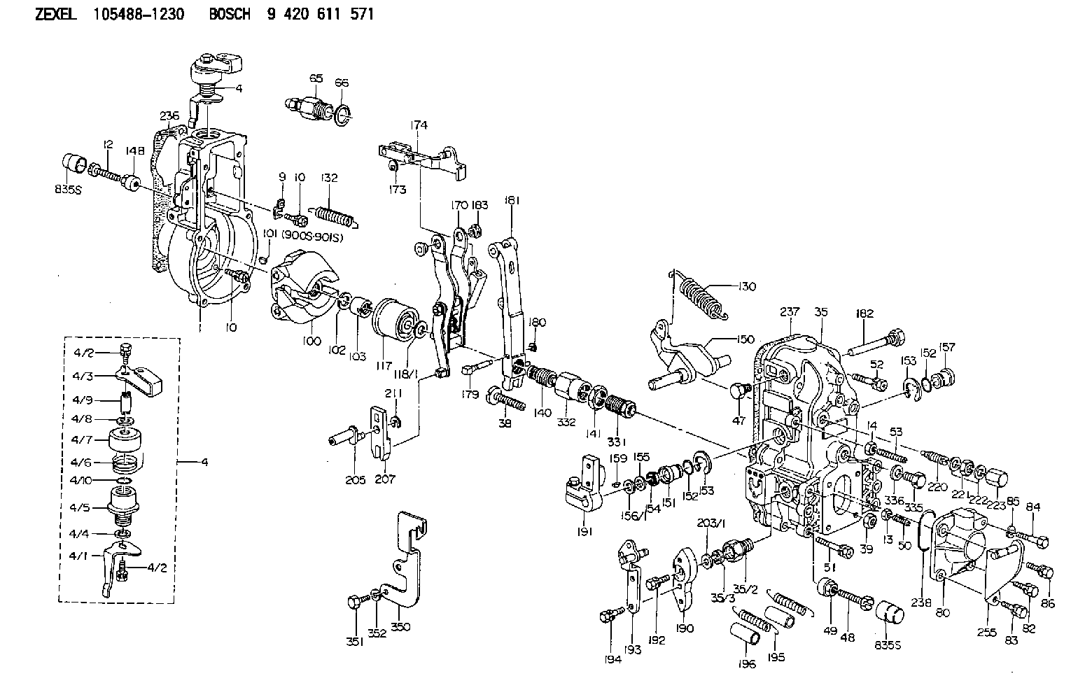
| 1. | [1] | 154000-9100 | GOVERNOR HOUSING |
| 4. | [1] | 154366-7020 | CONTROL LEVER |
| 4. | [1] | 154366-7020 | CONTROL LEVER |
| 4/1. | [1] | 154304-6200 | CONTROL LEVER |
| 4/2. | [2] | 154352-2000 | BLEEDER SCREW |
| 4/2. | [2] | 154352-2000 | BLEEDER SCREW |
| 4/3. | [1] | 154366-7000 | CONTROL LEVER |
| 4/4. | [1] | 029311-0230 | SHIM D18&10.3T0.5 |
| 4/5. | [1] | 154321-1500 | BUSHING |
| 4/6. | [1] | 154327-4100 | COILED SPRING |
| 4/7. | [1] | 154322-0100 | CAP |
| 4/8. | [1] | 029311-0220 | SHIM D18&10.3T0.2 |
| 4/9. | [1] | 154324-2700 | LEVER SHAFT |
| 4/10. | [1] | 029631-0030 | O-RING &9.8W2.3 |
| 9. | [1] | 154350-6000 | PLATE |
| 10. | [8] | 020106-2040 | BLEEDER SCREW M6P1L20 |
| 10. | [8] | 020106-2040 | BLEEDER SCREW M6P1L20 |
| 12. | [1] | 154010-7200 | BLEEDER SCREW M8P1.25L62 |
| 13. | [1] | 029240-6010 | UNION NUT M6P1.0H5* |
| 14. | [1] | 154011-0100 | HEXAGON NUT |
| 14B. | [1] | 154011-2300 | UNION NUT |
| 35. | [1] | 154513-6020 | GOVERNOR COVER |
| 35/2. | [1] | 154321-1800 | BUSHING |
| 35/3. | [1] | 029621-0080 | PACKING RING |
| 38. | [1] | 154031-3500 | FLAT-HEAD SCREW |
| 39. | [1] | 154011-1600 | UNION NUT |
| 47. | [1] | 154036-0300 | CAPSULE |
| 48. | [1] | 154010-7700 | BLEEDER SCREW M10P1.25L51 |
| 48B. | [1] | 154010-7100 | BLEEDER SCREW M10P1.25L47 |
| 49. | [1] | 154011-2200 | UNION NUT |
| 50. | [1] | 155615-1100 | FLAT-HEAD SCREW M6P1.0L37 |
| 51. | [4] | 020106-3840 | BLEEDER SCREW |
| 52. | [2] | 020106-5040 | BLEEDER SCREW |
| 53. | [1] | 154010-1100 | FLAT-HEAD SCREW |
| 65. | [1] | 153021-2220 | STOPPING DEVICE |
| 66. | [1] | 026524-3040 | GASKET |
| 80. | [1] | 154060-7300 | COVER |
| 82. | [1] | 029020-6210 | BLEEDER SCREW |
| 83. | [1] | 029020-6240 | BLEEDER SCREW |
| 84. | [1] | 010006-3840 | BLEEDER SCREW |
| 85. | [1] | 014110-6440 | LOCKING WASHER |
| 86. | [1] | 020006-1840 | BLEEDER SCREW M6P1L18 |
| 100. | [1] | 154100-9520 | FLYWEIGHT ASSEMBLY |
| 101. | [1] | 025803-1310 | WOODRUFF KEY |
| 102. | [1] | 029321-2020 | LOCKING WASHER |
| 103. | [1] | 029231-2030 | UNION NUT |
| 117. | [1] | 154123-2320 | SLIDING PIECE |
| 118/1. | [0] | 029311-0010 | SHIM D14&10.1T0.2 |
| 118/1. | [0] | 029311-0180 | SHIM D14&10.1T0.3 |
| 118/1. | [0] | 029311-0190 | SHIM D14&10.1T0.40 |
| 118/1. | [0] | 029311-0210 | SHIM D14&10.1T1 |
| 118/1. | [0] | 139410-0000 | SHIM D14.0&10.1T0.5 |
| 118/1. | [0] | 139410-0100 | SHIM D14.0&10.1T1.5 |
| 118/1. | [0] | 139410-3000 | SHIM D14&10.1T2.0 |
| 118/1. | [0] | 139410-3100 | SHIM D14&10.1T3.0 |
| 118/1. | [0] | 139410-3200 | SHIM D14&10.1T4.0 |
| 130. | [1] | 154150-6200 | GOVERNOR SPRING |
| 132. | [1] | 154154-4000 | COILED SPRING |
| 140. | [1] | 154180-0520 | HEADLESS SCREW |
| 141. | [1] | 029201-6220 | UNION NUT |
| 150. | [1] | 154200-3701 | SWIVELLING LEVER |
| 151. | [1] | 154204-2001 | BUSHING |
| 152. | [2] | 029631-8020 | O-RING |
| 152. | [2] | 029631-8020 | O-RING |
| 153. | [2] | 154354-3900 | LOCKING WASHER |
| 153. | [2] | 154354-3900 | LOCKING WASHER |
| 154. | [1] | 139611-0000 | PACKING RING |
| 155. | [1] | 139411-0000 | SHIM |
| 156/1. | [0] | 029311-1110 | SHIM D17&11T0.1 |
| 156/1. | [0] | 029311-1120 | SHIM D17&11T0.2 |
| 156/1. | [0] | 029311-1130 | SHIM D17&11T0.3 |
| 157. | [1] | 154204-3400 | BUSHING |
| 159. | [1] | 025803-1310 | WOODRUFF KEY |
| 170. | [1] | 154216-4120 | FORK LEVER |
| 173. | [1] | 016010-0540 | LOCKING WASHER |
| 174. | [1] | 154230-4920 | STRAP |
| 179. | [1] | 154238-0301 | BEARING PIN |
| 180. | [1] | 016010-0540 | LOCKING WASHER |
| 181. | [1] | 154236-7220 | TENSIONING LEVER |
| 182. | [1] | 154237-0900 | BEARING PIN |
| 183. | [2] | 154237-0600 | BUSHING |
| 190. | [1] | 154360-2700 | CONTROL LEVER |
| 191. | [1] | 154340-2220 | CONTROL LEVER |
| 192. | [1] | 020006-1670 | BLEEDER SCREW M6P1L16 7T |
| 193. | [1] | 154361-7020 | CONTROL LEVER |
| 194. | [2] | 020006-1240 | BLEEDER SCREW M6P1L12 4T |
| 195. | [2] | 154314-8900 | COILED SPRING |
| 196. | [2] | 154156-0900 | TUBE |
| 203/1. | [0] | 029311-0640 | SHIM D26.0&10.2T0.95 |
| 203/1. | [0] | 029311-0650 | SHIM D26.0&10.2T0.20 |
| 203/1. | [0] | 029311-0660 | SHIM D26.0&10.2T0.25 |
| 203/1. | [0] | 029311-0670 | SHIM D26.0&10.2T0.30 |
| 203/1. | [0] | 029311-0680 | SHIM D26.0&10.2T0.35 |
| 203/1. | [0] | 029311-0690 | SHIM D26.0&10.2T0.40 |
| 203/1. | [0] | 029311-0700 | SHIM D26.0&10.2T0.50 |
| 203/1. | [0] | 139410-1400 | SHIM D26&10.2T0.7 |
| 203/1. | [0] | 139410-1500 | SHIM D26&10.2T0.9 |
| 203/1. | [0] | 139410-1600 | SHIM D26&10.2T0.8 |
| 203/1. | [0] | 139410-2700 | SHIM D26&10.2T0.6 |
| 205. | [1] | 154324-3100 | LEVER SHAFT |
| 207. | [1] | 154326-6223 | CONTROL LEVER |
| 211. | [1] | 016010-0840 | LOCKING WASHER |
| 220. | [1] | 154050-3520 | HEADLESS SCREW |
| 221. | [1] | 029201-2140 | UNION NUT |
| 222. | [2] | 026512-1540 | GASKET D15.4&12.2T1.50 |
| 223. | [1] | 154159-1200 | CAP NUT |
| 236. | [1] | 154371-5600 | GASKET |
| 237. | [1] | 154390-0300 | GASKET |
| 238. | [1] | 029635-2020 | O-RING |
| 255. | [1] | 154213-7220 | BRACKET |
| 331. | [1] | 154179-3020 | HEADLESS SCREW |
| 332. | [1] | 029201-6010 | UNION NUT |
| 335. | [1] | 154352-2600 | CAPSULE |
| 336. | [1] | 029331-6030 | GASKET |
| 350. | [1] | 154354-3500 | BRACKET |
| 351. | [2] | 010010-1240 | BLEEDER SCREW M10P1.5L12 4T |
| 352. | [2] | 014111-0440 | LOCKING WASHER |
| 900S. | [1] | 025803-1310 | WOODRUFF KEY |
| 901S. | [1] | 025803-1610 | WOODRUFF KEY |
Include in #1:
106671-8240
as GOVERNOR
Cross reference number
Zexel num
Bosch num
Firm num
Name
Information:
start by:a) remove automatic timing advanceb) remove vibration damper and pulleyc) remove water pumpd) remove belt tightener idler pulleye) remove water temperature regulator (left cylinder head)1. Remove the tube assembly from the oil cooler elbow to the oil pan.2. Loosen the bolts that hold the oil pan to the cylinder block approximately 1/4" (6.4 mm). Remove the bolts that hold the oil pan to the timing gear cover.3. Fasten a hoist to the engine and lift it off tool (A). Weight of the engine is 3200 lb. (1452 kg). Make a separation of the oil pan from the cylinder block and timing gear cover. Do not damage the pan gasket.4. Put 1/4" (6.4 mm) pieces of bar stock between the pan and cylinder block at the positions the oil pan makes contact with tool (A). Lower the engine on tool (A).5. Remove the bolts from the belt tightener bracket. Remove the block and gasket. 6. Remove fumes disposal tube (1).7. Remove the bolts (4) that hold the timing gear cover to the cylinder block.8. Remove water bonnet (2).9. Remove timing gear cover (3).
Do not cause damage to the crankshaft front seal when the cover is removed.
10. Check the condition of the O-ring seal on the fuel injection pump housing.Install Timing Gear Cover
1. Put clean engine oil on the O-ring seal for the fuel injection pump housing, the crankshaft front seal and wear sleeve.2. Install tool (B) in the crankshaft front seal.3. Install a new gasket on the timing gear cover. Put timing gear cover (1) in position on the dowels in the cylinder block. Make sure it is against the cylinder block all around.4. Install the bolts that hold the cover in position. Remove tool (B) from the crankshaft front seal.5. Install the water bonnet, the fumes disposal tube and the block for the belt tightener bracket.6. Fasten a hoist to the engine and lift it off tool (A). Remove the bar stock from between the cylinder block and oil pan. Tighten the bolts that hold the oil pan to the cylinder block.7. Install the bolts that hold the oil pan to the timing gear cover. Put the engine back on tool (A).8. Install the tube assembly between the oil pan and oil cooler.end by:a) install water temperature regulator (left cylinder head)b) install belt tightener idler pulleyc) install water pumpd) install vibration damper and pulleye) install automatic timing advance