Information governor
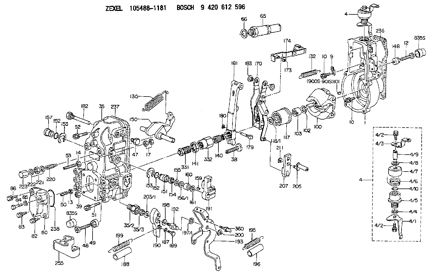
BOSCH
9 420 612 596
9420612596
ZEXEL
105488-1181
1054881181
Rating:
Scheme ###:
| 1. | [1] | 154000-4700 | GOVERNOR HOUSING |
| 4. | [1] | 154364-8820 | CONTROL LEVER |
| 4. | [1] | 154364-8820 | CONTROL LEVER |
| 4/1. | [1] | 154304-6200 | CONTROL LEVER |
| 4/2. | [2] | 154352-2000 | BLEEDER SCREW |
| 4/2. | [2] | 154352-2000 | BLEEDER SCREW |
| 4/3. | [1] | 154364-8800 | CONTROL LEVER |
| 4/4. | [1] | 029311-0230 | SHIM D18&10.3T0.5 |
| 4/5. | [1] | 154321-1500 | BUSHING |
| 4/6. | [1] | 154327-2901 | COILED SPRING |
| 4/7. | [1] | 154322-0100 | CAP |
| 4/8. | [1] | 029311-0220 | SHIM D18&10.3T0.2 |
| 4/9. | [1] | 154324-2700 | LEVER SHAFT |
| 4/10. | [1] | 029631-0030 | O-RING &9.8W2.3 |
| 9. | [1] | 154350-6000 | PLATE |
| 10. | [8] | 020106-2040 | BLEEDER SCREW M6P1L20 |
| 10. | [8] | 020106-2040 | BLEEDER SCREW M6P1L20 |
| 12. | [1] | 154010-7200 | BLEEDER SCREW M8P1.25L62 |
| 13. | [1] | 029240-6010 | UNION NUT M6P1.0H5* |
| 14. | [1] | 154011-0100 | HEXAGON NUT |
| 14B. | [1] | 154011-2300 | UNION NUT |
| 17. | [2] | 154011-1100 | UNION NUT |
| 35. | [1] | 154513-1420 | GOVERNOR COVER |
| 35/2. | [1] | 154321-1800 | BUSHING |
| 35/3. | [1] | 029621-0080 | PACKING RING |
| 38. | [1] | 154031-3500 | FLAT-HEAD SCREW |
| 39. | [1] | 154011-1600 | UNION NUT |
| 47. | [1] | 154036-0300 | CAPSULE |
| 48. | [1] | 154010-7100 | BLEEDER SCREW M10P1.25L47 |
| 49. | [1] | 154011-2200 | UNION NUT |
| 50. | [1] | 155615-1100 | FLAT-HEAD SCREW M6P1.0L37 |
| 51. | [4] | 020106-3840 | BLEEDER SCREW |
| 52. | [2] | 020106-5040 | BLEEDER SCREW |
| 53. | [1] | 154010-0100 | FLAT-HEAD SCREW |
| 65. | [1] | 153043-4320 | STOPPING DEVICE |
| 66. | [1] | 026524-3040 | GASKET |
| 80. | [1] | 154060-7900 | COVER |
| 82. | [1] | 029020-6240 | BLEEDER SCREW |
| 83. | [1] | 020006-1640 | BLEEDER SCREW M6P1L16 4T |
| 84. | [1] | 020506-3540 | BLEEDER SCREW |
| 85. | [1] | 014110-6440 | LOCKING WASHER |
| 86. | [1] | 020006-1640 | BLEEDER SCREW M6P1L16 4T |
| 100. | [1] | 154100-9520 | FLYWEIGHT ASSEMBLY |
| 101. | [1] | 025803-1310 | WOODRUFF KEY |
| 102. | [1] | 029321-2020 | LOCKING WASHER |
| 103. | [1] | 029231-2030 | UNION NUT |
| 117. | [1] | 154123-0420 | SLIDING PIECE |
| 118/1. | [0] | 029311-0010 | SHIM D14&10.1T0.2 |
| 118/1. | [0] | 029311-0180 | SHIM D14&10.1T0.3 |
| 118/1. | [0] | 029311-0190 | SHIM D14&10.1T0.40 |
| 118/1. | [0] | 029311-0210 | SHIM D14&10.1T1 |
| 118/1. | [0] | 139410-0000 | SHIM D14.0&10.1T0.5 |
| 118/1. | [0] | 139410-0100 | SHIM D14.0&10.1T1.5 |
| 118/1. | [0] | 139410-3000 | SHIM D14&10.1T2.0 |
| 118/1. | [0] | 139410-3100 | SHIM D14&10.1T3.0 |
| 118/1. | [0] | 139410-3200 | SHIM D14&10.1T4.0 |
| 130. | [1] | 154150-7200 | GOVERNOR SPRING |
| 132. | [1] | 154154-0701 | COILED SPRING |
| 140. | [1] | 154175-1520 | HEADLESS SCREW |
| 141. | [1] | 029201-6010 | UNION NUT |
| 150. | [1] | 154200-3801 | SWIVELLING LEVER |
| 151. | [1] | 154204-2001 | BUSHING |
| 152. | [2] | 029631-8020 | O-RING |
| 152. | [2] | 029631-8020 | O-RING |
| 153. | [2] | 154354-3900 | LOCKING WASHER |
| 153. | [2] | 154354-3900 | LOCKING WASHER |
| 154. | [1] | 139611-0000 | PACKING RING |
| 155. | [1] | 139411-0000 | SHIM |
| 156/1. | [0] | 029311-1110 | SHIM D17&11T0.1 |
| 156/1. | [0] | 029311-1120 | SHIM D17&11T0.2 |
| 156/1. | [0] | 029311-1130 | SHIM D17&11T0.3 |
| 157. | [1] | 154204-3400 | BUSHING |
| 159. | [1] | 025803-1310 | WOODRUFF KEY |
| 160. | [1] | 154206-0900 | BUSHING |
| 161. | [0] | 154206-0200 | PLAIN WASHER D19.5&11.2T1.0 |
| 170. | [1] | 154211-7720 | GUIDE LEVER |
| 173. | [1] | 016010-0540 | LOCKING WASHER |
| 174. | [1] | 154230-4920 | STRAP |
| 179. | [1] | 154238-0301 | BEARING PIN |
| 180. | [1] | 016010-0540 | LOCKING WASHER |
| 181. | [1] | 154236-5300 | TENSIONING LEVER |
| 182. | [1] | 154237-0900 | BEARING PIN |
| 183. | [2] | 154237-0600 | BUSHING |
| 187. | [1] | 014110-6440 | LOCKING WASHER |
| 188. | [1] | 154156-1500 | TUBE |
| 189. | [1] | 154357-6320 | BLEEDER SCREW |
| 190. | [1] | 154360-2800 | CONTROL LEVER |
| 191. | [1] | 154340-2020 | CONTROL LEVER |
| 192. | [1] | 154371-8300 | BLEEDER SCREW |
| 193. | [1] | 154368-9620 | CONTROL LEVER |
| 195. | [2] | 154317-5300 | COILED SPRING |
| 196. | [2] | 154156-0600 | TUBE |
| 197/1. | [0] | 029310-8610 | SHIM D10.5&8.5T0.1 |
| 197/1. | [0] | 029310-8620 | SHIM D10.5&8.5T0.15 |
| 197/1. | [0] | 029310-8630 | SHIM D10.5&8.5T0.2 |
| 197/1. | [0] | 029310-8650 | SHIM D10.5&8.5T0.5 |
| 198. | [1] | 014110-8440 | LOCKING WASHER |
| 199. | [1] | 154317-0900 | COILED SPRING |
| 200. | [1] | 016010-0740 | LOCKING WASHER |
| 203/1. | [0] | 029311-0640 | SHIM D26.0&10.2T0.95 |
| 203/1. | [0] | 029311-0650 | SHIM D26.0&10.2T0.20 |
| 203/1. | [0] | 029311-0660 | SHIM D26.0&10.2T0.25 |
| 203/1. | [0] | 029311-0670 | SHIM D26.0&10.2T0.30 |
| 203/1. | [0] | 029311-0680 | SHIM D26.0&10.2T0.35 |
| 203/1. | [0] | 029311-0690 | SHIM D26.0&10.2T0.40 |
| 203/1. | [0] | 029311-0700 | SHIM D26.0&10.2T0.50 |
| 203/1. | [0] | 139410-1400 | SHIM D26&10.2T0.7 |
| 203/1. | [0] | 139410-1500 | SHIM D26&10.2T0.9 |
| 203/1. | [0] | 139410-1600 | SHIM D26&10.2T0.8 |
| 203/1. | [0] | 139410-2700 | SHIM D26&10.2T0.6 |
| 205. | [1] | 154324-3000 | LEVER SHAFT |
| 207. | [1] | 154326-0300 | CONTROL LEVER |
| 211. | [1] | 016010-0840 | LOCKING WASHER |
| 220. | [1] | 154050-6820 | HEADLESS SCREW |
| 221. | [1] | 029201-2140 | UNION NUT |
| 222. | [2] | 139512-0000 | GASKET D17.2&12.2T1.0 |
| 223. | [1] | 154159-1200 | CAP NUT |
| 236. | [1] | 154371-5600 | GASKET |
| 237. | [1] | 154390-0300 | GASKET |
| 238. | [1] | 029635-2020 | O-RING |
| 255. | [1] | 154371-8520 | BRACKET |
| 331. | [1] | 154179-2620 | HEADLESS SCREW |
| 332. | [1] | 029201-6220 | UNION NUT |
| 360. | [1] | 154357-6900 | BEARING PIN |
| 835S. | [2] | 154062-1700 | CAP D20L32 |
| 835S. | [2] | 154062-1700 | CAP D20L32 |
| 900S. | [1] | 025803-1310 | WOODRUFF KEY |
| 901S. | [1] | 025803-1610 | WOODRUFF KEY |
Include in #1:
106693-1821
as GOVERNOR
Cross reference number
Zexel num
Bosch num
Firm num
Name
Information:
10. Remove pin (18), spring and plunger from control lever (14). 11. Remove bearings (19) and two seals (20) from governor housing (13). 12. Remove seat (21), spring washer (22), flat washer (24), spring washer (23) and spring (25). 13. Remove washer (27) from governor bolt (26).14. Remove ring (28) from seat (29). 15. Remove dowel (30) from seat (29). Remove seat (29) and governor bolt (26) as a unit. Remove bolt (26) from seat (29). 16. Remove washer (31), spring (32), washer (33) and sleeve (34) from the servo piston valve. 17. Remove ring (38), large race (37), bearing (35) and small race (36) from sleeve (34). 18. Remove lock (40) from flyweight assembly (39). Remove flyweight assembly (40). 19. Bend the locks from bolts (41) and remove bolts (41).20. Remove bracket (42) and the servo piston assembly as a unit. 21. Remove piston (44) from pin (43). Remove pin (43) from bracket (42). 22. Remove sleeve (45) and valve (46) from piston (44). Remove O-ring seal (47) from sleeve (45). 23. Remove shaft (48) from bracket (42) with a hammer and punch.24. Remove lever (49) from bracket (42). 25. Hit (tap) lightly on cylinder (50) to remove it from the governor plate. 26. Remove O-ring seals (51) from cylinder (50). 27. Remove spiral ring (53), and then remove dowel (52) behind the spiral ring. 28. Remove drive assembly (54) and stop (55) from drive gear (56). 29. Turn the governor plate over and remove snap ring (57) from drive gear (56) with tool (B).30. Remove drive gear (56) from the governor plate. 31. If a replacement is needed, remove dowels (59), (60) and (61).32. Remove bearing (58) from the governor plate with tooling (A).Assemble Governor
1. If a replacement of the dowels in the governor plate is necessary, see illustration for correct installation dimensions. 2. Install bearing (1) for drive gear (2) in governor plate (3) with tooling (A) until it is .020 .010 in. (0.51 0.25 mm) below the top surface of the governor plate. 3. Put a small amount of clean engine oil on the inside diameter of bearing (1). Install drive gear (2) in governor plate (3). 4. Turn governor plate (3) over and install snap ring (4) that holds drive gear (2) in place. 5. Install O-ring seals (6) on cylinder (5). 6. Put a small amount of clean engine oil on the O-ring seals on cylinder (5). Install cylinder (5) in the governor plate with the notch in the cylinder in alignment with the bolt hole in the governor plate as shown.7. Install the O-ring seal on sleeve (9).8. Put a small amount of clean engine oil on piston (7), sleeve (9) and valve (8). Install sleeve (9) on piston (7) and valve (8) in piston (7) as shown.9. Install the servo piston assembly in cylinder (5). The valve (8), sleeve (9) and piston (7) are parts of the servo piston assembly. 10. Put lever (11) in position in bracket
1. If a replacement of the dowels in the governor plate is necessary, see illustration for correct installation dimensions. 2. Install bearing (1) for drive gear (2) in governor plate (3) with tooling (A) until it is .020 .010 in. (0.51 0.25 mm) below the top surface of the governor plate. 3. Put a small amount of clean engine oil on the inside diameter of bearing (1). Install drive gear (2) in governor plate (3). 4. Turn governor plate (3) over and install snap ring (4) that holds drive gear (2) in place. 5. Install O-ring seals (6) on cylinder (5). 6. Put a small amount of clean engine oil on the O-ring seals on cylinder (5). Install cylinder (5) in the governor plate with the notch in the cylinder in alignment with the bolt hole in the governor plate as shown.7. Install the O-ring seal on sleeve (9).8. Put a small amount of clean engine oil on piston (7), sleeve (9) and valve (8). Install sleeve (9) on piston (7) and valve (8) in piston (7) as shown.9. Install the servo piston assembly in cylinder (5). The valve (8), sleeve (9) and piston (7) are parts of the servo piston assembly. 10. Put lever (11) in position in bracket