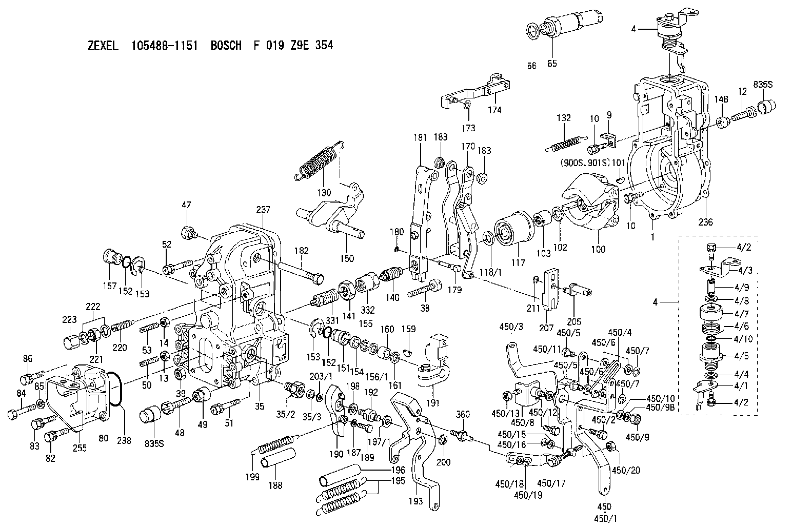
Information governor
BOSCH
F 019 Z9E 354
f019z9e354
ZEXEL
105488-1151
1054881151
Rating:
Scheme ###:
| 1. | [1] | 154000-4700 | GOVERNOR HOUSING |
| 4. | [1] | 154364-8820 | CONTROL LEVER |
| 4. | [1] | 154364-8820 | CONTROL LEVER |
| 4/1. | [1] | 154304-6200 | CONTROL LEVER |
| 4/2. | [2] | 154352-2000 | BLEEDER SCREW |
| 4/2. | [2] | 154352-2000 | BLEEDER SCREW |
| 4/3. | [1] | 154364-8800 | CONTROL LEVER |
| 4/4. | [1] | 029311-0230 | SHIM D18&10.3T0.5 |
| 4/5. | [1] | 154321-1500 | BUSHING |
| 4/6. | [1] | 154327-2901 | COILED SPRING |
| 4/7. | [1] | 154322-0100 | CAP |
| 4/8. | [1] | 029311-0220 | SHIM D18&10.3T0.2 |
| 4/9. | [1] | 154324-2700 | LEVER SHAFT |
| 4/10. | [1] | 029631-0030 | O-RING &9.8W2.3 |
| 9. | [1] | 154350-6000 | PLATE |
| 10. | [8] | 020106-2040 | BLEEDER SCREW M6P1L20 |
| 10. | [8] | 020106-2040 | BLEEDER SCREW M6P1L20 |
| 12. | [1] | 154010-7200 | BLEEDER SCREW M8P1.25L62 |
| 13. | [1] | 029240-6010 | UNION NUT M6P1.0H5* |
| 14. | [1] | 154011-0100 | HEXAGON NUT |
| 14B. | [1] | 154011-2300 | UNION NUT |
| 35. | [1] | 154513-1420 | GOVERNOR COVER |
| 35/2. | [1] | 154321-1800 | BUSHING |
| 35/3. | [1] | 029621-0080 | PACKING RING |
| 38. | [1] | 154031-3500 | FLAT-HEAD SCREW |
| 39. | [1] | 154011-1600 | UNION NUT |
| 47. | [1] | 154036-0300 | CAPSULE |
| 48. | [1] | 154010-7100 | BLEEDER SCREW M10P1.25L47 |
| 49. | [1] | 154011-2200 | UNION NUT |
| 50. | [1] | 155615-1100 | FLAT-HEAD SCREW M6P1.0L37 |
| 51. | [4] | 020106-3840 | BLEEDER SCREW |
| 52. | [2] | 020106-5040 | BLEEDER SCREW |
| 53. | [1] | 154010-0100 | FLAT-HEAD SCREW |
| 65. | [1] | 153043-4320 | STOPPING DEVICE |
| 66. | [1] | 026524-3040 | GASKET |
| 80. | [1] | 154060-7900 | COVER |
| 82. | [1] | 029020-6240 | BLEEDER SCREW |
| 83. | [1] | 020006-1640 | BLEEDER SCREW M6P1L16 4T |
| 84. | [1] | 020506-3540 | BLEEDER SCREW |
| 85. | [1] | 014110-6440 | LOCKING WASHER |
| 86. | [1] | 020006-1640 | BLEEDER SCREW M6P1L16 4T |
| 100. | [1] | 154100-9520 | FLYWEIGHT ASSEMBLY |
| 101. | [1] | 025803-1310 | WOODRUFF KEY |
| 102. | [1] | 029321-2020 | LOCKING WASHER |
| 103. | [1] | 029231-2030 | UNION NUT |
| 117. | [1] | 154123-0420 | SLIDING PIECE |
| 118/1. | [0] | 029311-0010 | SHIM D14&10.1T0.2 |
| 118/1. | [0] | 029311-0180 | SHIM D14&10.1T0.3 |
| 118/1. | [0] | 029311-0190 | SHIM D14&10.1T0.40 |
| 118/1. | [0] | 029311-0210 | SHIM D14&10.1T1 |
| 118/1. | [0] | 139410-0000 | SHIM D14.0&10.1T0.5 |
| 118/1. | [0] | 139410-0100 | SHIM D14.0&10.1T1.5 |
| 118/1. | [0] | 139410-3000 | SHIM D14&10.1T2.0 |
| 118/1. | [0] | 139410-3100 | SHIM D14&10.1T3.0 |
| 118/1. | [0] | 139410-3200 | SHIM D14&10.1T4.0 |
| 130. | [1] | 154150-7200 | GOVERNOR SPRING |
| 132. | [1] | 154154-0200 | COILED SPRING |
| 140. | [1] | 154175-1520 | HEADLESS SCREW |
| 141. | [1] | 029201-6010 | UNION NUT |
| 150. | [1] | 154200-3801 | SWIVELLING LEVER |
| 151. | [1] | 154204-2001 | BUSHING |
| 152. | [2] | 029631-8020 | O-RING |
| 152. | [2] | 029631-8020 | O-RING |
| 153. | [2] | 154354-3900 | LOCKING WASHER |
| 153. | [2] | 154354-3900 | LOCKING WASHER |
| 154. | [1] | 139611-0000 | PACKING RING |
| 155. | [1] | 139411-0000 | SHIM |
| 156/1. | [0] | 029311-1110 | SHIM D17&11T0.1 |
| 156/1. | [0] | 029311-1120 | SHIM D17&11T0.2 |
| 156/1. | [0] | 029311-1130 | SHIM D17&11T0.3 |
| 157. | [1] | 154204-3400 | BUSHING |
| 159. | [1] | 025803-1310 | WOODRUFF KEY |
| 160. | [1] | 154206-0900 | BUSHING |
| 161. | [0] | 154206-0200 | PLAIN WASHER D19.5&11.2T1.0 |
| 170. | [1] | 154211-7720 | GUIDE LEVER |
| 173. | [1] | 016010-0540 | LOCKING WASHER |
| 174. | [1] | 154230-4920 | STRAP |
| 179. | [1] | 154238-0301 | BEARING PIN |
| 180. | [1] | 016010-0540 | LOCKING WASHER |
| 181. | [1] | 154236-5300 | TENSIONING LEVER |
| 182. | [1] | 154237-0900 | BEARING PIN |
| 183. | [2] | 154237-0600 | BUSHING |
| 183. | [2] | 154237-0600 | BUSHING |
| 187. | [1] | 014110-6440 | LOCKING WASHER |
| 188. | [1] | 154156-1500 | TUBE |
| 189. | [1] | 154357-6320 | BLEEDER SCREW |
| 190. | [1] | 154360-2800 | CONTROL LEVER |
| 191. | [1] | 154340-0020 | CONTROL LEVER |
| 192. | [1] | 154371-8300 | BLEEDER SCREW |
| 193. | [1] | 154368-9820 | CONTROL LEVER |
| 195. | [2] | 154317-4800 | COILED SPRING |
| 196. | [2] | 154156-1800 | TUBE |
| 197/1. | [0] | 029310-8610 | SHIM D10.5&8.5T0.1 |
| 197/1. | [0] | 029310-8620 | SHIM D10.5&8.5T0.15 |
| 197/1. | [0] | 029310-8630 | SHIM D10.5&8.5T0.2 |
| 197/1. | [0] | 029310-8650 | SHIM D10.5&8.5T0.5 |
| 198. | [1] | 014110-8440 | LOCKING WASHER |
| 199. | [1] | 154317-0900 | COILED SPRING |
| 200. | [1] | 016010-0740 | LOCKING WASHER |
| 203/1. | [0] | 029311-0640 | SHIM D26.0&10.2T0.95 |
| 203/1. | [0] | 029311-0650 | SHIM D26.0&10.2T0.20 |
| 203/1. | [0] | 029311-0660 | SHIM D26.0&10.2T0.25 |
| 203/1. | [0] | 029311-0670 | SHIM D26.0&10.2T0.30 |
| 203/1. | [0] | 029311-0680 | SHIM D26.0&10.2T0.35 |
| 203/1. | [0] | 029311-0690 | SHIM D26.0&10.2T0.40 |
| 203/1. | [0] | 029311-0700 | SHIM D26.0&10.2T0.50 |
| 203/1. | [0] | 139410-1400 | SHIM D26&10.2T0.7 |
| 203/1. | [0] | 139410-1500 | SHIM D26&10.2T0.9 |
| 203/1. | [0] | 139410-1600 | SHIM D26&10.2T0.8 |
| 203/1. | [0] | 139410-2700 | SHIM D26&10.2T0.6 |
| 205. | [1] | 154324-3000 | LEVER SHAFT |
| 207. | [1] | 154326-0300 | CONTROL LEVER |
| 211. | [1] | 016010-0840 | LOCKING WASHER |
| 220. | [1] | 154050-6820 | HEADLESS SCREW |
| 221. | [1] | 029201-2140 | UNION NUT |
| 222. | [2] | 139512-0000 | GASKET D17.2&12.2T1.0 |
| 223. | [1] | 154159-1200 | CAP NUT |
| 236. | [1] | 154371-5600 | GASKET |
| 237. | [1] | 154390-0300 | GASKET |
| 238. | [1] | 029635-2020 | O-RING |
| 255. | [1] | 154371-8520 | BRACKET |
| 331. | [1] | 154179-2620 | HEADLESS SCREW |
| 332. | [1] | 029201-6220 | UNION NUT |
| 360. | [1] | 154357-6900 | BEARING PIN |
| 450. | [1] | 154399-4421 | LEVER GROUP |
| 450/1. | [1] | 154358-9800 | CONTROL LEVER |
| 450/2. | [2] | 020006-1640 | BLEEDER SCREW M6P1L16 4T |
| 450/3. | [1] | 154372-0520 | CONTROL LEVER |
| 450/4. | [1] | 154370-9300 | STRAP |
| 450/5. | [2] | 154352-1200 | BEARING PIN |
| 450/5. | [2] | 154352-1200 | BEARING PIN |
| 450/6. | [4] | 014011-0140 | PLAIN WASHER D22&10.5T1.6 |
| 450/6. | [4] | 014011-0140 | PLAIN WASHER D22&10.5T1.6 |
| 450/7. | [2] | 016010-0940 | LOCKING WASHER |
| 450/7. | [2] | 016010-0940 | LOCKING WASHER |
| 450/8. | [1] | 154372-0720 | BRACKET |
| 450/9. | [1] | 013020-8040 | UNION NUT M8P1.25H7 |
| 450/9B. | [1] | 014110-8440 | LOCKING WASHER |
| 450/10. | [1] | 014010-8140 | PLAIN WASHER D18&8.5T1.6 |
| 450/11. | [1] | 139412-0000 | SHIM |
| 450/12. | [1] | 020018-3040 | BLEEDER SCREW M8P1.25L30 |
| 450/13. | [1] | 013120-8040 | UNION NUT M8P1.25H6.5 |
| 450/15. | [1] | 014010-6140 | PLAIN WASHER D13&6.5T1 |
| 450/16. | [1] | 016010-0640 | LOCKING WASHER |
| 450/17. | [1] | 154371-6020 | STRAP |
| 450/18. | [1] | 014010-6140 | PLAIN WASHER D13&6.5T1 |
| 450/19. | [1] | 016010-0640 | LOCKING WASHER |
| 450/20. | [1] | 013020-6040 | UNION NUT M6P1H5 |
| 835S. | [2] | 154062-1700 | CAP D20L32 |
| 835S. | [2] | 154062-1700 | CAP D20L32 |
| 900S. | [1] | 025803-1310 | WOODRUFF KEY |
| 901S. | [1] | 025803-1610 | WOODRUFF KEY |
Cross reference number
Zexel num
Bosch num
Firm num
Name
Information:
8. Remove O-ring seal (10), the thrust washer and the bearing from the adapter with tool (A).9. Remove bolts (12) from the cover. Remove cover (11) and the gasket from the crankcase. 10. Bend down the lock on lock straps (13). Remove bolts (14) from the bearing caps.11. Put identification on the bearing caps for correct installation with the connecting rod. Remove the bearing caps. 12. Remove pistons (15) from the crankcase through the top of the cylinders.13. Remove crankshaft (16) from the crankcase. Remove the key from the crankshaft. 14. Remove end cover (17) from the crankcase. Remove the O-ring seal, the thrust washer and the bearing.15. Remove cover (18), the gasket and the strainer from the air inlet opening. 16. Remove inlet valves (20) from their guides (21). Remove the inlet valve guides from around the inlet valve seats.
Be careful not to cause damage to the inlet valve seats.
17. Remove (unloader) spring (19), spring saddle (22) and the spring seat from the housing with needle nose pliers. 18. Remove (unloader) plunger (24) and guides (25) from the housing. Remove the guides from the plungers to plungers.19. To remove (unloader) pistons (23) from the bore, put a cover over the inlet port, then blow air pressure in the governor mounting pad (unloader) port. 20. Remove lockpin (27) that holds rod pin (26) in the piston. Remove the pin from connecting rod (28). 21. Remove the piston rings from piston (30). Remove two compression rings (29), the oil ring and the expander ring with tool (B).22. Remove the bearings from the connecting rod and the connecting rod cap. 23. Remove the piston pin bushing with tool (C).24. Remove the small seal rings from both ends of the housing.25. Clean all the oil passages through the housing, the crankshaft, the end cover and the adapter.Assemble Air Compressor
1. Check (unloader) bore bushings (1) for damage and wear. If these bushings need replacement, remove the bushing by the use of a 1/8 in. (3.18 mm) pipe threaded tap. Then install a 1/8 in. (3.18 mm) pipe threaded rod and pull the bushing straight up and out.2. Check the cylinder bores in the crankcase housing for damages (scored or out of round). Measure the cylinder bore in several places. If the measurement difference is more than .001 in. (0.03 mm) or taper is more than .002 (0.05 mm), the cylinder bore must be made larger (rebored or honed oversize). See SPECIFICATIONS.3. Install seal rings (3) in both ends of the crankcase housing.4. Install the new (unloader) pistons in their bore.
Be careful not to cause damage to the O-ring seals or the spiral rings.
5. Put the unloader plungers in their guides. Install the plunger and guide as a unit (6) to the crankcase housing and on top of the pistons. Install the unloader spring seat in the crankcase housing.6. Put saddle (4) in position between the unloader piston guides. Install (unloader) spring (8). Make sure it makes a seat on the spring seats