Information governor
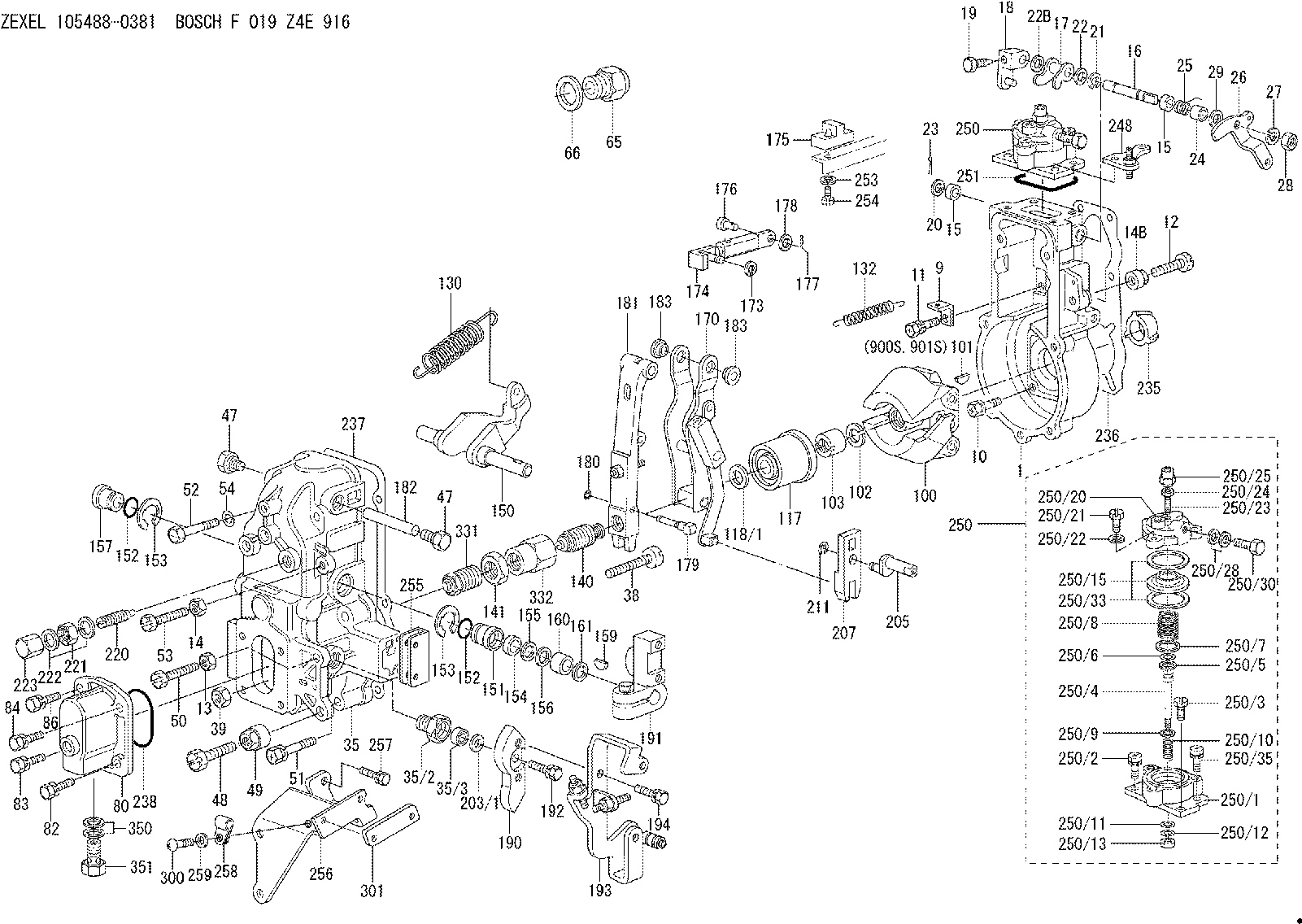
BOSCH
F 019 Z4E 916
f019z4e916
ZEXEL
105488-0381
1054880381
MITSUBISHI
ME726593
me726593
Rating:
Scheme ###:
| 1. | [1] | 154004-1022 | GOVERNOR HOUSING |
| 9. | [1] | 154350-6000 | PLATE |
| 10. | [4] | 020106-2040 | BLEEDER SCREW |
| 11. | [4] | 020106-1840 | BLEEDER SCREW |
| 12. | [1] | 154010-7200 | BLEEDER SCREW |
| 13. | [1] | 013020-6040 | UNION NUT |
| 14. | [1] | 013020-8040 | UNION NUT |
| 14B. | [1] | 154011-2300 | UNION NUT |
| 15. | [2] | 029620-8050 | PACKING RING |
| 15. | [2] | 029620-8050 | PACKING RING |
| 16. | [1] | 155004-3301 | LEVER SHAFT |
| 17. | [1] | 154408-1520 | CONTROL LEVER |
| 18. | [1] | 155003-1920 | CONTROL LEVER |
| 19. | [1] | 155006-0700 | BLEEDER SCREW |
| 20. | [1] | 139308-0900 | PLAIN WASHER D16&8T1 |
| 20B. | [1] | 139308-1000 | PLAIN WASHER D16&8T1.5 |
| 21. | [1] | 016010-0740 | LOCKING WASHER |
| 22. | [0] | 029310-8040 | SHIM D13.5&8T0.2 |
| 22B. | [0] | 029310-8050 | SHIM D13.5&8T0.5 |
| 23. | [1] | 025520-1210 | SPLIT PIN |
| 24. | [1] | 154206-2000 | BUSHING |
| 25. | [1] | 154327-5200 | COILED SPRING |
| 26. | [1] | 154365-2400 | CONTROL LEVER |
| 27. | [1] | 014110-8440 | LOCKING WASHER D15.4&8.2T2 |
| 28. | [1] | 013020-8040 | UNION NUT |
| 29. | [1] | 139408-1400 | SHIM D16&8T0.2 |
| 29B. | [0] | 139408-1400 | SHIM D16&8T0.2 |
| 29C. | [0] | 139408-1500 | SHIM D16&8T0.5 |
| 35. | [1] | 154514-4920 | GOVERNOR COVER |
| 35/2. | [1] | 154321-2000 | BUSHING |
| 35/3. | [1] | 029621-0080 | PACKING RING |
| 38. | [1] | 154031-3401 | FLAT-HEAD SCREW |
| 39. | [1] | 029201-0160 | UNION NUT |
| 47. | [2] | 154036-1800 | CAPSULE |
| 47. | [2] | 154036-1800 | CAPSULE |
| 48. | [1] | 154010-7100 | BLEEDER SCREW M10P1.25L47 |
| 48B. | [1] | 154010-8200 | BLEEDER SCREW M10P1.25L45 |
| 49. | [1] | 154011-2200 | UNION NUT |
| 50. | [1] | 155615-1900 | BLEEDER SCREW |
| 51. | [5] | 020106-4540 | BLEEDER SCREW |
| 52. | [2] | 029010-6850 | BLEEDER SCREW |
| 53. | [1] | 154010-7300 | BLEEDER SCREW |
| 54. | [2] | 014110-6440 | LOCKING WASHER D12.2&6.1T1.5 |
| 65. | [1] | 153021-2720 | STOPPING DEVICE |
| 66. | [1] | 026524-3040 | GASKET |
| 80. | [1] | 154063-6121 | COVER |
| 82. | [1] | 029020-6240 | BLEEDER SCREW |
| 83. | [1] | 020006-1640 | BLEEDER SCREW |
| 84. | [1] | 029020-6240 | BLEEDER SCREW |
| 86. | [1] | 020006-1640 | BLEEDER SCREW |
| 100. | [1] | 154100-9220 | FLYWEIGHT ASSEMBLY |
| 101. | [1] | 025803-1310 | WOODRUFF KEY 13 MM |
| 102. | [1] | 029321-2020 | LOCKING WASHER |
| 103. | [1] | 139212-0000 | UNION NUT |
| 117. | [1] | 154123-2320 | SLIDING PIECE |
| 118/1. | [0] | 029311-0010 | SHIM D14&10.1T0.2 |
| 118/1. | [0] | 029311-0180 | SHIM D14&10.1T0.3 |
| 118/1. | [0] | 029311-0190 | SHIM D14&10.1T0.40 |
| 118/1. | [0] | 029311-0210 | SHIM D14&10.1T1 |
| 118/1. | [0] | 139410-0000 | SHIM D14&10.1T0.5 |
| 118/1. | [0] | 139410-0100 | SHIM D14&10.1T1.5 |
| 118/1. | [0] | 139410-3000 | SHIM D14&10.1T2.0 |
| 118/1. | [0] | 139410-3100 | SHIM D14&10.1T3.0 |
| 118/1. | [0] | 139410-3200 | SHIM D14&10.1T4.0 |
| 130. | [1] | 154150-7900 | GOVERNOR SPRING |
| 132. | [1] | 154154-0701 | COILED SPRING |
| 140. | [1] | 154183-1020 | HEADLESS SCREW |
| 141. | [1] | 139218-0100 | UNION NUT |
| 150. | [1] | 154200-5401 | SWIVELLING LEVER |
| 151. | [1] | 154200-5501 | BUSHING |
| 152. | [2] | 139700-0000 | O-RING |
| 152. | [2] | 139700-0000 | O-RING |
| 153. | [2] | 154354-3900 | LOCKING WASHER |
| 153. | [2] | 154354-3900 | LOCKING WASHER |
| 154. | [1] | 139610-0101 | PACKING RING |
| 155. | [1] | 139411-0100 | SHIM |
| 156. | [0] | 139411-0200 | SHIM D18.0&12.0T0.10 |
| 156B. | [0] | 139411-0300 | SHIM D18.0&12.0T0.20 |
| 156C. | [0] | 139411-0400 | SHIM D18.0&12.0T0.30 |
| 157. | [1] | 154204-3500 | BUSHING |
| 159. | [1] | 025803-1310 | WOODRUFF KEY 13 MM |
| 160. | [1] | 154206-2300 | BUSHING |
| 161. | [0] | 154206-2400 | PLAIN WASHER D20.5&12.2T1 |
| 170. | [1] | 154216-1920 | FORK LEVER |
| 173. | [1] | 016010-0540 | LOCKING WASHER |
| 174. | [1] | 154234-0320 | STRAP |
| 175. | [1] | 154232-1720 | PLATE |
| 176. | [1] | 159231-4900 | BEARING PIN |
| 177. | [1] | 155402-3800 | SAFETY PIN |
| 178. | [1] | 029310-5170 | SHIM |
| 179. | [1] | 154238-0201 | BEARING PIN |
| 180. | [1] | 016010-0540 | LOCKING WASHER |
| 181. | [1] | 154236-5200 | TENSIONING LEVER |
| 182. | [1] | 154237-1200 | BEARING PIN |
| 183. | [2] | 154237-1300 | BUSHING |
| 183. | [2] | 154237-1300 | BUSHING |
| 190. | [1] | 154360-2800 | CONTROL LEVER |
| 191. | [1] | 154340-1920 | CONTROL LEVER |
| 192. | [1] | 020006-1670 | BLEEDER SCREW |
| 193. | [1] | 154368-0720 | CONTROL LEVER |
| 194. | [2] | 020006-1240 | BLEEDER SCREW |
| 203/1. | [0] | 029311-0640 | SHIM D26.0&10.2T0.95 |
| 203/1. | [0] | 029311-0650 | SHIM D26.0&10.2T0.20 |
| 203/1. | [0] | 029311-0660 | SHIM D26.0&10.2T0.25 |
| 203/1. | [0] | 029311-0670 | SHIM D26.0&10.2T0.30 |
| 203/1. | [0] | 029311-0680 | SHIM D26.0&10.2T0.35 |
| 203/1. | [0] | 029311-0690 | SHIM D26.0&10.2T0.40 |
| 203/1. | [0] | 029311-0700 | SHIM D26.0&10.2T0.50 |
| 203/1. | [0] | 139410-1400 | SHIM D26&10.2T0.7 |
| 203/1. | [0] | 139410-1500 | SHIM D26&10.2T0.9 |
| 203/1. | [0] | 139410-1600 | SHIM D26&10.2T0.8 |
| 203/1. | [0] | 139410-2700 | SHIM D26&10.2T0.6 |
| 205. | [1] | 154324-2900 | LEVER SHAFT |
| 207. | [1] | 154326-0300 | CONTROL LEVER |
| 211. | [1] | 016010-0840 | LOCKING WASHER |
| 220. | [1] | 154050-6220 | HEADLESS SCREW |
| 221. | [1] | 029201-2130 | UNION NUT |
| 222. | [2] | 026512-1540 | GASKET |
| 223. | [1] | 154159-1200 | CAP NUT |
| 235. | [1] | 155412-5200 | IMPELLER WHEEL |
| 236. | [1] | 154371-5600 | GASKET |
| 237. | [1] | 154390-0200 | GASKET |
| 238. | [1] | 139700-0100 | O-RING |
| 248. | [1] | 154356-9320 | BRACKET |
| 250. | [1] | 154418-0621 | MANIFOLD-PRESSURE COMP. |
| 250. | [1] | 154418-0621 | MANIFOLD-PRESSURE COMP. |
| 250/1. | [1] | 154408-6220 | DIAPHRAGM HOUSING |
| 250/2. | [2] | 020106-1640 | BLEEDER SCREW |
| 250/3. | [1] | 029020-6260 | BLEEDER SCREW |
| 250/4. | [1] | 154400-5800 | STOP PIN |
| 250/5. | [1] | 153400-0900 | SLOTTED WASHER |
| 250/6. | [1] | 016010-0740 | LOCKING WASHER |
| 250/7. | [0] | 029312-0180 | SHIM D25.5&20T0.5 |
| 250/7B. | [0] | 029312-0210 | SHIM D25.5&20T0.2 |
| 250/8. | [1] | 154403-8400 | COILED SPRING |
| 250/9. | [0] | 154355-3900 | SHIM D18&12.5T0.10 |
| 250/9B. | [0] | 154355-4000 | SHIM D18&12.5T0.20 |
| 250/9C. | [0] | 154355-4100 | SHIM D18&12.5T0.30 |
| 250/10. | [1] | 154411-2200 | COILED SPRING |
| 250/11. | [1] | 153400-0800 | SPRING SEAT |
| 250/12. | [1] | 014110-5440 | LOCKING WASHER |
| 250/13. | [1] | 013030-5240 | UNION NUT |
| 250/15. | [1] | 154400-9320 | DIAPHRAGM |
| 250/20. | [1] | 154404-5100 | COVER |
| 250/21. | [3] | 029010-6310 | BLEEDER SCREW |
| 250/22. | [3] | 014110-6440 | LOCKING WASHER D12.2&6.1T1.5 |
| 250/23. | [1] | 154404-5300 | FLAT-HEAD SCREW |
| 250/24. | [1] | 023040-6040 | UNION NUT |
| 250/25. | [1] | 154406-7800 | CAP NUT |
| 250/28. | [2] | 026510-1340 | GASKET |
| 250/30. | [1] | 029731-0180 | EYE BOLT |
| 250/33. | [2] | 154413-2600 | GASKET |
| 250/35. | [1] | 020106-2040 | BLEEDER SCREW |
| 251. | [1] | 154358-2500 | SEAL RING |
| 253. | [1] | 029320-5020 | LOCKING WASHER |
| 254. | [1] | 010535-1040 | FLAT-HEAD SCREW |
| 255. | [1] | 154359-4400 | BRACKET |
| 256. | [1] | 154359-4520 | BRACKET |
| 257. | [1] | 020106-1040 | BLEEDER SCREW M6P1.0L12 |
| 258. | [1] | 154604-0200 | CLAMPING BAND |
| 259. | [1] | 014010-4140 | PLAIN WASHER |
| 300. | [1] | 012154-0640 | FLAT-HEAD SCREW M4P0.7L6 |
| 301. | [1] | 154359-7700 | PLATE |
| 331. | [1] | 154179-6520 | HEADLESS SCREW |
| 332. | [1] | 139218-0200 | UNION NUT |
| 350. | [2] | 026512-1840 | GASKET |
| 351. | [1] | 153556-4800 | EYE BOLT |
| 900S. | [1] | 025803-1310 | WOODRUFF KEY 13 MM |
| 901S. | [1] | 025803-1610 | WOODRUFF KEY 16 MM |
Include in #1:
106671-7231
as GOVERNOR
Cross reference number
Zexel num
Bosch num
Firm num
Name
Information:
Installation Procedure
The installation procedure that follows is specific for the listed machine.Diesel Particulate Filter Installation
Illustration 6 g01782176
(2) 331-9206 Bracket As (15) 8T-4223 Hard Washer (16) 8F-6437 Washer (17) 8T-4139 Bolt (19) 6V-8149 Nut
Install the new 331-9206 Bracket As (2) on top of the hood using two new 6V-87149 Nuts (19), one new 8F-6437 Washer (16), three new 8T-4223 Hard Washers (16), and two new 8T-4139 Bolts (17). Refer to Illustration 6.
Illustration 7 g01782178
(3) 331-9212 Bracket (20) 8T-3597 Weld Nut
Connect 331-9212 Bracket (3) to the hood and to bracket assembly (2) using four new 8T-3597 Weld Nuts (20), three new washers (16), one new hard washer (15), and four new bolts (17). Refer to Illustration 7.
Illustration 8 g01782181
(6) 295-3044 Exhaust Support Gp (Lower half)
Install the lower halves of 295-3044 Exhaust Support Gp (6) on bracket assembly (2) using two new washers (16), two new hard washers (15), and four new bolts (17). Refer to Illustration 8.
Illustration 9 g01782193
(1) 331-8928 Diesel Particulate Filter Gp (6) 295-3044 Exhaust Support Gp (Upper half) (6a) Bolt (6b) Hard washer (6c) Weld nut
Place 331-8928 Diesel Particulate Filter Gp (1) onto the two lower halves of exhaust support group (6). The weight of the diesel particulate filter group is approximately 44 kg (97 lb). Refer to Illustration 9.
Install the two upper halves of exhaust support group (6) onto the lower halves of exhaust support group (6) using four hard washers (6b), four weld nuts (6c), and four bolts (6a). Refer to Illustration 9.
Illustration 10 g01782194
(a) Outlet module tube (11) 7S-8735 Clamp (13) 255-2899 Tail Pipe As (18) 8T-4186 Bolt (21) 8T-4133 Nut
Connect the new 255-2899 Tail Pipe As (13) to outlet module tube (a) of diesel particulate filter group (1) using one new 7S-8735 Clamp (11), one new 8T-4186 Bolt (18) and one new 8T-4133 Nut (21). Refer to Illustration 10.
Illustration 11 g01782200
(b) Inlet module tube (4) 331-9214 Filter Tube As (9) 8T-6765 Pipe Plug (8) 241-6170 Plug (12) 209-4589 Clamp
Connect the new 331-9214 Filter Tube As (4) to inlet module tube (b) of diesel particulate filter group using one new 209-4589 Clamp (12). Refer to Illustration 11.
Install the new 8T-6765 Pipe Plug (9) and 241-6170 Plug (8) onto the respective bosses provided on filter tube assembly (4). Refer to Illustration 11.
Illustration 12 g01782206
(7) 270-0112 Bellows
Connect the new 270-0112 Bellows (7) to filter tube assembly (4) using one clamp new (12). Refer to Illustration 12.
Illustration 13 g01782215
(5) 331-9213 Filter Tube
Connect the new 331-9213 Filter Tube (5) to bellows (7) using one new clamp (12). Refer to Illustration 13.
Illustration 14 g01782235
(10) 7E-3870 Muffler Clamp (14) 146-9734 Exhaust Elbow
Connect the new 146-9734 Exhaust Elbow (14) to filter tube (5) using a new 7E-3870 Muffler Clamp (10). Refer to