Information governor
BOSCH
F 019 Z1E 170
f019z1e170
ZEXEL
105488-0073
1054880073
Rating:
Scheme ###:
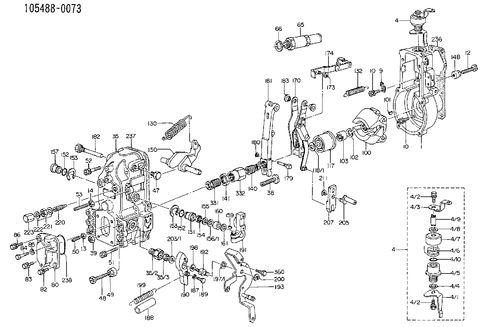
| 1. | [1] | 154000-4700 | GOVERNOR HOUSING |
| 4. | [1] | 154364-8820 | CONTROL LEVER |
| 4. | [1] | 154364-8820 | CONTROL LEVER |
| 4/1. | [1] | 154304-6200 | CONTROL LEVER |
| 4/2. | [2] | 154352-2000 | BLEEDER SCREW |
| 4/2. | [2] | 154352-2000 | BLEEDER SCREW |
| 4/3. | [1] | 154364-8800 | CONTROL LEVER |
| 4/4. | [1] | 029311-0230 | SHIM D18&10.3T0.5 |
| 4/5. | [1] | 154321-1500 | BUSHING |
| 4/6. | [1] | 154327-2901 | COILED SPRING |
| 4/7. | [1] | 154322-0100 | CAP |
| 4/8. | [1] | 029311-0220 | SHIM D18&10.3T0.2 |
| 4/9. | [1] | 154324-2700 | LEVER SHAFT |
| 4/10. | [1] | 029631-0030 | O-RING &9.8W2.3 |
| 9. | [1] | 154350-6000 | PLATE |
| 10. | [8] | 020106-2040 | BLEEDER SCREW M6P1L20 |
| 10. | [8] | 020106-2040 | BLEEDER SCREW M6P1L20 |
| 12. | [1] | 154010-7200 | BLEEDER SCREW M8P1.25L62 |
| 13. | [1] | 029240-6010 | UNION NUT M6P1.0H5* |
| 14. | [1] | 154011-0100 | HEXAGON NUT |
| 14B. | [1] | 154011-2300 | UNION NUT |
| 35. | [1] | 154513-1420 | GOVERNOR COVER |
| 35/2. | [1] | 154321-1800 | BUSHING |
| 35/3. | [1] | 029621-0080 | PACKING RING |
| 38. | [1] | 154031-3500 | FLAT-HEAD SCREW |
| 39. | [1] | 154011-1600 | UNION NUT |
| 47. | [1] | 154036-0300 | CAPSULE |
| 48. | [1] | 154010-7100 | BLEEDER SCREW M10P1.25L47 |
| 49. | [1] | 154011-2200 | UNION NUT |
| 50. | [1] | 155615-1100 | FLAT-HEAD SCREW M6P1.0L37 |
| 51. | [4] | 020106-3840 | BLEEDER SCREW |
| 52. | [2] | 020106-5040 | BLEEDER SCREW |
| 53. | [1] | 154010-0100 | FLAT-HEAD SCREW |
| 65. | [1] | 153043-4320 | STOPPING DEVICE |
| 66. | [1] | 026524-3040 | GASKET |
| 80. | [1] | 154060-7900 | COVER |
| 82. | [1] | 029020-6210 | BLEEDER SCREW |
| 83. | [1] | 020006-1640 | BLEEDER SCREW M6P1L16 4T |
| 84. | [1] | 029020-6220 | BLEEDER SCREW |
| 85. | [1] | 014110-6440 | LOCKING WASHER |
| 86. | [1] | 020006-1640 | BLEEDER SCREW M6P1L16 4T |
| 100. | [1] | 154100-9520 | FLYWEIGHT ASSEMBLY |
| 101. | [1] | 025803-1310 | WOODRUFF KEY |
| 102. | [1] | 029321-2020 | LOCKING WASHER |
| 103. | [1] | 029231-2030 | UNION NUT |
| 117. | [1] | 154123-0420 | SLIDING PIECE |
| 118/1. | [0] | 029311-0010 | SHIM D14&10.1T0.2 |
| 118/1. | [0] | 029311-0180 | SHIM D14&10.1T0.3 |
| 118/1. | [0] | 029311-0190 | SHIM D14&10.1T0.40 |
| 118/1. | [0] | 029311-0210 | SHIM D14&10.1T1 |
| 118/1. | [0] | 139410-0000 | SHIM D14.0&10.1T0.5 |
| 118/1. | [0] | 139410-0100 | SHIM D14.0&10.1T1.5 |
| 118/1. | [0] | 139410-3000 | SHIM D14&10.1T2.0 |
| 118/1. | [0] | 139410-3100 | SHIM D14&10.1T3.0 |
| 118/1. | [0] | 139410-3200 | SHIM D14&10.1T4.0 |
| 130. | [1] | 154150-7200 | GOVERNOR SPRING |
| 132. | [1] | 154154-0701 | COILED SPRING |
| 140. | [1] | 154175-1520 | HEADLESS SCREW |
| 141. | [1] | 029201-6010 | UNION NUT |
| 150. | [1] | 154200-3801 | SWIVELLING LEVER |
| 151. | [1] | 154204-2001 | BUSHING |
| 152. | [2] | 029631-8020 | O-RING |
| 152. | [2] | 029631-8020 | O-RING |
| 153. | [2] | 154354-3900 | LOCKING WASHER |
| 153. | [2] | 154354-3900 | LOCKING WASHER |
| 154. | [1] | 139611-0000 | PACKING RING |
| 155. | [1] | 139411-0000 | SHIM |
| 156/1. | [0] | 029311-1110 | SHIM D17&11T0.1 |
| 156/1. | [0] | 029311-1120 | SHIM D17&11T0.2 |
| 156/1. | [0] | 029311-1130 | SHIM D17&11T0.3 |
| 157. | [1] | 154204-3400 | BUSHING |
| 159. | [1] | 025803-1310 | WOODRUFF KEY |
| 160. | [1] | 154206-0900 | BUSHING |
| 161. | [0] | 154206-0200 | PLAIN WASHER D19.5&11.2T1.0 |
| 170. | [1] | 154211-7720 | GUIDE LEVER |
| 173. | [1] | 016010-0540 | LOCKING WASHER |
| 174. | [1] | 154230-4920 | STRAP |
| 179. | [1] | 154238-0301 | BEARING PIN |
| 180. | [1] | 016010-0540 | LOCKING WASHER |
| 181. | [1] | 154236-5300 | TENSIONING LEVER |
| 182. | [1] | 154237-0900 | BEARING PIN |
| 183. | [2] | 154237-0600 | BUSHING |
| 187. | [1] | 014110-6440 | LOCKING WASHER |
| 188. | [1] | 154156-1500 | TUBE |
| 189. | [1] | 154357-6320 | BLEEDER SCREW |
| 190. | [1] | 154360-2800 | CONTROL LEVER |
| 191. | [1] | 154340-0020 | CONTROL LEVER |
| 192. | [1] | 154357-6401 | BLEEDER SCREW |
| 193. | [1] | 154362-6120 | CONTROL LEVER |
| 197/1. | [0] | 029310-8610 | SHIM D10.5&8.5T0.1 |
| 197/1. | [0] | 029310-8620 | SHIM D10.5&8.5T0.15 |
| 197/1. | [0] | 029310-8630 | SHIM D10.5&8.5T0.2 |
| 197/1. | [0] | 029310-8650 | SHIM D10.5&8.5T0.5 |
| 198. | [1] | 014110-8440 | LOCKING WASHER |
| 199. | [1] | 154317-0900 | COILED SPRING |
| 200. | [1] | 016010-0740 | LOCKING WASHER |
| 203/1. | [0] | 029311-0640 | SHIM D26.0&10.2T0.95 |
| 203/1. | [0] | 029311-0650 | SHIM D26.0&10.2T0.20 |
| 203/1. | [0] | 029311-0660 | SHIM D26.0&10.2T0.25 |
| 203/1. | [0] | 029311-0670 | SHIM D26.0&10.2T0.30 |
| 203/1. | [0] | 029311-0680 | SHIM D26.0&10.2T0.35 |
| 203/1. | [0] | 029311-0690 | SHIM D26.0&10.2T0.40 |
| 203/1. | [0] | 029311-0700 | SHIM D26.0&10.2T0.50 |
| 203/1. | [0] | 139410-1400 | SHIM D26&10.2T0.7 |
| 203/1. | [0] | 139410-1500 | SHIM D26&10.2T0.9 |
| 203/1. | [0] | 139410-1600 | SHIM D26&10.2T0.8 |
| 203/1. | [0] | 139410-2700 | SHIM D26&10.2T0.6 |
| 205. | [1] | 154324-3000 | LEVER SHAFT |
| 207. | [1] | 154326-0300 | CONTROL LEVER |
| 211. | [1] | 016010-0840 | LOCKING WASHER |
| 220. | [1] | 154050-6820 | HEADLESS SCREW |
| 221. | [1] | 029201-2140 | UNION NUT |
| 222. | [2] | 139512-0000 | GASKET D17.2&12.2T1.0 |
| 223. | [1] | 154159-1200 | CAP NUT |
| 236. | [1] | 154371-5600 | GASKET |
| 237. | [1] | 154390-0300 | GASKET |
| 238. | [1] | 029635-2020 | O-RING |
| 331. | [1] | 154179-2620 | HEADLESS SCREW |
| 332. | [1] | 029201-6220 | UNION NUT |
| 360. | [1] | 154357-6900 | BEARING PIN |
| 835S. | [2] | 154062-1700 | CAP D20L32 |
| 900S. | [1] | 025803-1310 | WOODRUFF KEY |
| 901S. | [1] | 025803-1610 | WOODRUFF KEY |
Include in #1:
106693-1053
as GOVERNOR
Cross reference number
Zexel num
Bosch num
Firm num
Name
Information:
Illustration 23. (2) 141-6737 Adjustable Microgauge.
(7) Top of the 3P-1542 Barrel. (8) 141-6727 Calibration Pump Assembly.1. Place the 141-6737 Adjustable Microgauge on top of the 3P-1542 Barrel of the 141-6727 Calibration Pump Assembly.2. When starting to torque 124-5932 Lever Assemblies, the difference between the face of the 141-6730 Plunger and the 2N-2658 Bolt is about 0.03 mm (.001 in). By setting the 141-6737 Adjustable Microgauge (2) on top of the 141-6727 Calibration Pump Assembly (8), the 141-6737 Plunger can be positioned 25.40 mm (.001 in) above the face of the 3P-1542 Barrel (7).
Illustration 24. (9) 2N-2658 Bolt. (10) 124-5940 Shutoff Lever.3. As the 2N-2658 Bolt (9) is torqued, the 141-6730 Plunger will move down flush with the 3P-1542 Barrel (7) or will be very close to being flush. The calibration can begin from this point. The 2N-2658 Bolts must freely turn in and out of the 124-5940 Shutoff Levers (10) because the calibration depends on where the head of the 2N-2658 Bolt (9) first begins to clamp the 124-5940 Shutoff Lever for the starting point of the calibration.End Play Adjustment
1. In order to save time, use two torque wrenches (color-coding is convenient for distinguishing between the two wrenches). Set one torque wrench to 1.7 N m (15 lb in) and the second torque wrench to N m (35 lb in).
Illustration 25. (1) 124-5941 Shaft. (2) 4N-1826 Dowel on one end of the HSMFS Injection Pump Group. (3) 126-7232 Dowels.2. Adjust the end play in the 124-5941 Shaft. The SMFS 109-0324 Governor And Fuel Injection Pump Group had the dowel in the middle of the sleeve and a large amount of end play in the shaft was acceptable. Now that the 126-7232 Dowels (3) are between two 124-5934 Sleeves, the amount of end play is important. It is necessary that an adjustment be performed to minimize the amount of end play in the 124-5941 Shaft (1).3. The 126-7232 Dowels (3) are located between two 124-5934 Sleeves. Set the 126-7232 Dowels between 0.25 to 0.40 mm (.010 to .016 in) by tapping in the 4N-1826 Dowels (2) until the desired end play is achieved.* With the 1.7 N m (15 lb in) torque wrench, torque the 2N-2658 Bolts to 1.7 N m (15 lb in).* Then use the 4 N m (35 lb in) torque wrench to torque the 2N-2658 Bolts to 3.4 N m (30 lb in) in order to calibrate within specifications.Calibrating the 124-5932 Lever Assemblies.
Illustration 26. Calibrating the 124-5932 Lever Assemblies.
(1) 2N-2658 Bolts. (2) 124-5940 Shutoff Lever.1. Begin with the first 2N-2658 Bolt (1) and turn it until it just begins to clamp (feels snug) on the 124-5940 Shutoff Lever (2).2. Move to the other side and turn the second 2N-2658 Bolt (1) until just begins to clamp (feels snug).* Alternate between sides and tighten each 2N-2658 Bolt about 15 degrees each time.
Illustration 27. View of the HSMFS Injection Pump Group.
(3) Top of the 141-6730 Plunger shown flush with the 3P-1542 Barrel (4).3. Continue until the torque