Information governor
BOSCH
9 420 614 195
9420614195
ZEXEL
105487-6740
1054876740
Rating:
Scheme ###:
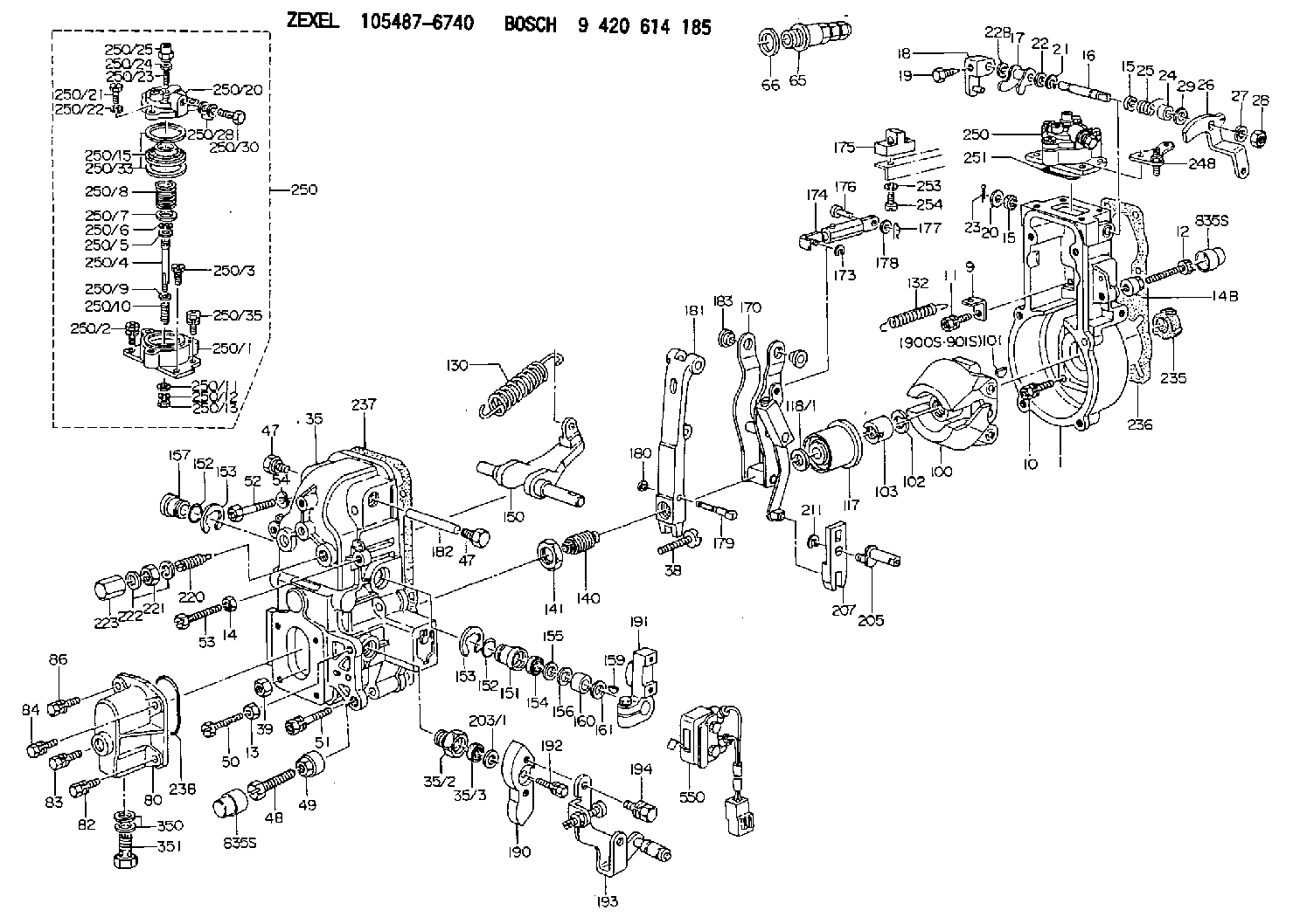
| 1. | [1] | 154004-1022 | GOVERNOR HOUSING |
| 9. | [1] | 154350-6000 | PLATE |
| 10. | [4] | 020106-2040 | BLEEDER SCREW M6P1L20 |
| 11. | [4] | 020106-1840 | BLEEDER SCREW M6P1L18 |
| 12. | [1] | 154010-7300 | BLEEDER SCREW M8P1.25L60 |
| 13. | [1] | 013020-6040 | UNION NUT M6P1H5 |
| 14. | [1] | 013020-8040 | UNION NUT M8P1.25H7 |
| 14B. | [1] | 154011-2300 | UNION NUT |
| 15. | [2] | 029620-8050 | PACKING RING |
| 15. | [2] | 029620-8050 | PACKING RING |
| 16. | [1] | 155004-3301 | LEVER SHAFT |
| 17. | [1] | 154408-1520 | CONTROL LEVER |
| 18. | [1] | 155003-1920 | CONTROL LEVER |
| 19. | [1] | 155006-0700 | BLEEDER SCREW |
| 20. | [1] | 139308-0900 | PLAIN WASHER D16&8T1 |
| 20B. | [1] | 139308-1000 | PLAIN WASHER D16&8T1.5 |
| 21. | [1] | 016010-0740 | LOCKING WASHER |
| 22. | [0] | 029310-8040 | SHIM D13.5&8T0.2 |
| 22B. | [0] | 029310-8050 | SHIM D13.5&8T0.5 |
| 23. | [1] | 025520-1210 | SPLIT PIN |
| 24. | [1] | 154206-2000 | BUSHING |
| 25. | [1] | 154327-5200 | COILED SPRING |
| 26. | [1] | 154365-2400 | CONTROL LEVER |
| 27. | [1] | 014110-8440 | LOCKING WASHER |
| 28. | [1] | 013020-8040 | UNION NUT M8P1.25H7 |
| 29. | [1] | 139408-1400 | SHIM |
| 29B. | [0] | 139408-1400 | SHIM |
| 29C. | [0] | 139408-1500 | SHIM |
| 35. | [1] | 154513-5820 | GOVERNOR COVER |
| 35/2. | [1] | 154321-2000 | BUSHING |
| 35/3. | [1] | 029621-0080 | PACKING RING |
| 38. | [1] | 154031-3401 | FLAT-HEAD SCREW |
| 39. | [1] | 029201-0160 | UNION NUT |
| 47. | [2] | 154036-1800 | CAPSULE |
| 47. | [2] | 154036-1800 | CAPSULE |
| 48. | [1] | 154010-7100 | BLEEDER SCREW M10P1.25L47 |
| 48B. | [1] | 154010-5500 | BLEEDER SCREW M10P1.25L42 |
| 49. | [1] | 154011-2200 | UNION NUT |
| 50. | [1] | 155615-1900 | BLEEDER SCREW |
| 51. | [5] | 020106-4540 | BLEEDER SCREW M6P1.0L45 |
| 52. | [2] | 029010-6850 | BLEEDER SCREW |
| 53. | [1] | 154010-7300 | BLEEDER SCREW M8P1.25L60 |
| 54. | [2] | 014110-6440 | LOCKING WASHER |
| 65. | [1] | 155404-1700 | CAP |
| 66. | [1] | 026524-3040 | GASKET |
| 80. | [1] | 154063-6121 | COVER |
| 82. | [1] | 029020-6210 | BLEEDER SCREW |
| 83. | [1] | 020006-1640 | BLEEDER SCREW M6P1L16 4T |
| 84. | [1] | 029020-6210 | BLEEDER SCREW |
| 86. | [1] | 020006-1640 | BLEEDER SCREW M6P1L16 4T |
| 100. | [1] | 154100-9220 | FLYWEIGHT ASSEMBLY |
| 101. | [1] | 025803-1310 | WOODRUFF KEY |
| 102. | [1] | 029321-2020 | LOCKING WASHER |
| 103. | [1] | 139212-0000 | UNION NUT |
| 117. | [1] | 154123-2320 | SLIDING PIECE |
| 118/1. | [0] | 029311-0010 | SHIM D14&10.1T0.2 |
| 118/1. | [0] | 029311-0180 | SHIM D14&10.1T0.3 |
| 118/1. | [0] | 029311-0190 | SHIM D14&10.1T0.40 |
| 118/1. | [0] | 029311-0210 | SHIM D14&10.1T1 |
| 118/1. | [0] | 139410-0000 | SHIM D14.0&10.1T0.5 |
| 118/1. | [0] | 139410-0100 | SHIM D14.0&10.1T1.5 |
| 118/1. | [0] | 139410-3000 | SHIM D14&10.1T2.0 |
| 118/1. | [0] | 139410-3100 | SHIM D14&10.1T3.0 |
| 118/1. | [0] | 139410-3200 | SHIM D14&10.1T4.0 |
| 130. | [1] | 154150-7900 | GOVERNOR SPRING |
| 132. | [1] | 154154-0701 | COILED SPRING |
| 140. | [1] | 154183-8820 | HEADLESS SCREW |
| 141. | [1] | 139218-0100 | UNION NUT |
| 150. | [1] | 154200-5401 | SWIVELLING LEVER |
| 151. | [1] | 154200-5501 | BUSHING |
| 152. | [2] | 139700-0000 | O-RING |
| 152. | [2] | 139700-0000 | O-RING |
| 153. | [2] | 154354-3900 | LOCKING WASHER |
| 153. | [2] | 154354-3900 | LOCKING WASHER |
| 154. | [1] | 139610-0101 | PACKING RING |
| 155. | [1] | 139411-0100 | SHIM D22.0&12.0T0.40 |
| 156. | [0] | 139411-0200 | SHIM D18.0&12.0T0.10 |
| 156B. | [0] | 139411-0300 | SHIM D18.0&12.0T0.20 |
| 156C. | [0] | 139411-0400 | SHIM D18.0&12.0T0.30 |
| 157. | [1] | 154204-3500 | BUSHING |
| 159. | [1] | 025803-1310 | WOODRUFF KEY |
| 160. | [1] | 154206-2300 | BUSHING |
| 161. | [0] | 154206-2400 | PLAIN WASHER D20.5&12.2T1 |
| 170. | [1] | 154216-1920 | FORK LEVER |
| 173. | [1] | 016010-0540 | LOCKING WASHER |
| 174. | [1] | 154234-8220 | STRAP |
| 175. | [1] | 154232-1220 | PLATE |
| 176. | [1] | 159231-4900 | BEARING PIN |
| 177. | [1] | 155402-3800 | SAFETY PIN |
| 178. | [1] | 029310-5170 | SHIM D8&5.3T0.5 |
| 179. | [1] | 154238-0201 | BEARING PIN |
| 180. | [1] | 016010-0540 | LOCKING WASHER |
| 181. | [1] | 154236-5200 | TENSIONING LEVER |
| 182. | [1] | 154237-1200 | BEARING PIN |
| 183. | [2] | 154237-1300 | BUSHING |
| 190. | [1] | 154360-2800 | CONTROL LEVER |
| 191. | [1] | 154340-1920 | CONTROL LEVER |
| 192. | [1] | 020006-1670 | BLEEDER SCREW M6P1L16 7T |
| 193. | [1] | 154368-3520 | CONTROL LEVER |
| 194. | [2] | 020006-1240 | BLEEDER SCREW M6P1L12 4T |
| 203/1. | [0] | 029311-0640 | SHIM D26.0&10.2T0.95 |
| 203/1. | [0] | 029311-0650 | SHIM D26.0&10.2T0.20 |
| 203/1. | [0] | 029311-0660 | SHIM D26.0&10.2T0.25 |
| 203/1. | [0] | 029311-0670 | SHIM D26.0&10.2T0.30 |
| 203/1. | [0] | 029311-0680 | SHIM D26.0&10.2T0.35 |
| 203/1. | [0] | 029311-0690 | SHIM D26.0&10.2T0.40 |
| 203/1. | [0] | 029311-0700 | SHIM D26.0&10.2T0.50 |
| 203/1. | [0] | 139410-1400 | SHIM D26&10.2T0.7 |
| 203/1. | [0] | 139410-1500 | SHIM D26&10.2T0.9 |
| 203/1. | [0] | 139410-1600 | SHIM D26&10.2T0.8 |
| 203/1. | [0] | 139410-2700 | SHIM D26&10.2T0.6 |
| 205. | [1] | 154324-2900 | LEVER SHAFT |
| 207. | [1] | 154326-0300 | CONTROL LEVER |
| 211. | [1] | 016010-0840 | LOCKING WASHER |
| 220. | [1] | 154050-1220 | HEADLESS SCREW |
| 221. | [1] | 029201-2130 | UNION NUT M12P1.0H6 |
| 222. | [2] | 026512-1540 | GASKET D15.4&12.2T1.50 |
| 223. | [1] | 154159-1200 | CAP NUT |
| 235. | [1] | 155412-5200 | IMPELLER WHEEL |
| 236. | [1] | 154371-5600 | GASKET |
| 237. | [1] | 154390-0200 | GASKET |
| 238. | [1] | 139700-0100 | O-RING |
| 248. | [1] | 154356-9320 | BRACKET |
| 250. | [1] | 154420-8620 | MANIFOLD-PRESSURE COMP. |
| 250. | [1] | 154420-8620 | MANIFOLD-PRESSURE COMP. |
| 250/1. | [1] | 154408-6220 | DIAPHRAGM HOUSING |
| 250/2. | [2] | 020106-1640 | BLEEDER SCREW M6P1.0L14 |
| 250/3. | [1] | 029020-6260 | BLEEDER SCREW |
| 250/4. | [1] | 154400-5800 | STOP PIN |
| 250/5. | [1] | 153400-0900 | SLOTTED WASHER |
| 250/6. | [1] | 016010-0740 | LOCKING WASHER |
| 250/7. | [0] | 029312-0180 | SHIM D25.5&20T0.5 |
| 250/7B. | [0] | 029312-0210 | SHIM D25.5&20T0.2 |
| 250/8. | [1] | 154402-3100 | COILED SPRING |
| 250/9. | [0] | 154355-3900 | SHIM D18&12.5T0.10 |
| 250/9B. | [0] | 154355-4000 | SHIM D18&12.5T0.20 |
| 250/9C. | [0] | 154355-4100 | SHIM D18&12.5T0.30 |
| 250/10. | [1] | 154402-2000 | COILED SPRING |
| 250/11. | [1] | 153400-0800 | SPRING SEAT |
| 250/12. | [1] | 014110-5440 | LOCKING WASHER |
| 250/13. | [1] | 013030-5240 | UNION NUT M5P0.8H3.2 |
| 250/15. | [1] | 154400-9320 | DIAPHRAGM |
| 250/20. | [1] | 154404-5100 | COVER |
| 250/21. | [3] | 029010-6310 | BLEEDER SCREW |
| 250/22. | [3] | 014110-6440 | LOCKING WASHER |
| 250/23. | [1] | 154404-5300 | FLAT-HEAD SCREW |
| 250/24. | [1] | 023040-6040 | UNION NUT |
| 250/25. | [1] | 154406-7800 | CAP NUT |
| 250/28. | [2] | 026510-1340 | GASKET D13.4&10.2T1 |
| 250/30. | [1] | 029731-0180 | EYE BOLT |
| 250/33. | [2] | 154413-2600 | GASKET |
| 250/35. | [1] | 020106-2040 | BLEEDER SCREW M6P1L20 |
| 251. | [1] | 154358-2500 | SEAL RING |
| 253. | [1] | 029320-5020 | LOCKING WASHER |
| 254. | [1] | 010535-1040 | FLAT-HEAD SCREW M5P0.8L10 |
| 350. | [2] | 026512-1840 | GASKET D17.9&12.2T1.50 |
| 351. | [1] | 153556-4800 | EYE BOLT |
| 550. | [1] | 153146-1120 | MICROSWITCH |
| 835S. | [2] | 154062-1700 | CAP D20L32 |
| 835S. | [2] | 154062-1700 | CAP D20L32 |
| 900S. | [1] | 025803-1310 | WOODRUFF KEY |
| 901S. | [1] | 025803-1610 | WOODRUFF KEY |
Include in #1:
106671-9111
as GOVERNOR
Cross reference number
Zexel num
Bosch num
Firm num
Name
Information:
The purpose of the air induction system is to provide clean air to the engine in an efficient, unrestricted, silent manner while the exhaust system discharges exhaust gases as quickly and as silently as possible with minimum backpressure. Engine horsepower and efficiently will be reduced if either the air inlet or exhaust becomes restricted. Good maintenance practice cannot be over emphasized. AIR CLEANERS: Regular service intervals, along with close visual inspection of the air cleaner, are necessary for proper cleaning of the engine inlet air. The service interval will vary with the weather and working conditions. Where dust conditions are severe, it will be necessary to service the air cleaner frequently. In damp weather and other conditions of little or no dust, the service interval can be extended.To extend the service life of the element, the exhaust and air cleaner inlet pipes should be arranged so that exhaust and/or oil fumes do not enter the engine air cleaner.Visual inspection of the gaskets and seals is important in keeping dust from by-passing the air cleaner. Any dirt allowed to enter, accelerates wear throughout the engine. If the condition of any of the replaceable seals and gaskets is questionable, replace them. If the sealing ends of the filter element or the element pleats are damaged. replace the element.Extra filter elements should be kept on hand for replacement or for use in the air cleaner while the element that was removed is being cleaned.When equipped with a dry-type air cleaner, a service indicator similar to the one shown is available. The air cleaner service indicator is connected to the air inlet pipe between the air cleaner and the manifold. It contains a red marked piston, which gradually rises with restriction to the air flow. When the entire piston is visible it will lock in this position. This indicates a need for air cleaner service. The piston will remain in this position whether or not the engine is running. After servicing the air cleaner, reset the piston by depressing the plunger in the bottom of the indicator.Excessive engine exhaust smoke and/or loss of power may indicate the need for servicing the air cleaner. Never service the air cleaner while the engine is running.(See your truck manufacturer's operator's books for maintenance intervals and instructions.) Air cleaner restriction at high idle should not exceed 25 inches (635 mm) of water.Valve Lash
Make valve lash adjustment with engine stopped.Top dead center (TDC) of the No. 1 piston on the compression stroke is the reference point. The No. 1 piston is at TDC compression stroke when the timing mark on the crankshaft damper or the pulley is aligned with the timing pointer, and No. 1 and No. 2 exhaust and inlet valves are closed. (The rocker arms are free.) To Adjust The Valve Lash
1. Adjust lash for No. 1 and No. 2 exhaust and inlet valves. a. Loosen valve adjusting screw locknut.b. Turn adjusting screw to allow a clearance gauge to pass between the top of