Information governor
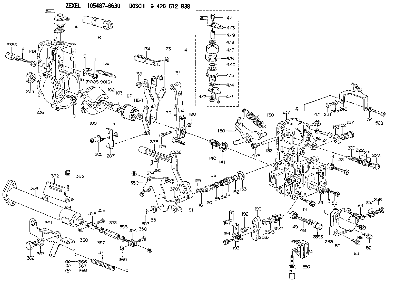
BOSCH
9 420 612 838
9420612838
ZEXEL
105487-6630
1054876630
Rating:
Scheme ###:
| 1. | [1] | 154004-0100 | GOVERNOR HOUSING |
| 4. | [1] | 154365-2220 | CONTROL LEVER |
| 4. | [1] | 154365-2220 | CONTROL LEVER |
| 4/1. | [1] | 154304-6200 | CONTROL LEVER |
| 4/2. | [1] | 154352-2000 | BLEEDER SCREW |
| 4/3. | [1] | 154365-2200 | CONTROL LEVER |
| 4/4. | [1] | 029311-0230 | SHIM D18&10.3T0.5 |
| 4/5. | [1] | 154321-1500 | BUSHING |
| 4/6. | [1] | 154327-6701 | COILED SPRING |
| 4/7. | [1] | 154322-0100 | CAP |
| 4/8. | [1] | 029311-0220 | SHIM D18&10.3T0.2 |
| 4/9. | [1] | 154324-2700 | LEVER SHAFT |
| 4/10. | [1] | 029631-0030 | O-RING &9.8W2.3 |
| 4/11. | [1] | 020006-1240 | BLEEDER SCREW M6P1L12 4T |
| 9. | [1] | 154350-6000 | PLATE |
| 10. | [4] | 020106-2040 | BLEEDER SCREW M6P1L20 |
| 11. | [4] | 020106-1840 | BLEEDER SCREW M6P1L18 |
| 12. | [1] | 154010-7400 | BLEEDER SCREW M8P1.25L55 |
| 13. | [1] | 013020-6040 | UNION NUT M6P1H5 |
| 14. | [1] | 013020-8040 | UNION NUT M8P1.25H7 |
| 14B. | [1] | 154011-2300 | UNION NUT |
| 35. | [1] | 154516-3120 | GOVERNOR COVER |
| 35/2. | [1] | 154321-2000 | BUSHING |
| 35/3. | [1] | 029621-0080 | PACKING RING |
| 38. | [1] | 154031-3401 | FLAT-HEAD SCREW |
| 39. | [1] | 029201-0160 | UNION NUT |
| 47. | [1] | 154036-1900 | CAPSULE |
| 47B. | [1] | 154036-1800 | CAPSULE |
| 48. | [1] | 154010-6000 | BLEEDER SCREW M10P1.25L55 |
| 48B. | [1] | 154010-7700 | BLEEDER SCREW M10P1.25L51 |
| 49. | [1] | 154011-2200 | UNION NUT |
| 50. | [1] | 155615-1900 | BLEEDER SCREW |
| 51. | [5] | 020106-4540 | BLEEDER SCREW M6P1.0L45 |
| 52. | [1] | 010006-6040 | BLEEDER SCREW |
| 52B. | [1] | 029010-6850 | BLEEDER SCREW |
| 53. | [1] | 154010-7300 | BLEEDER SCREW M8P1.25L60 |
| 54. | [2] | 014110-6440 | LOCKING WASHER |
| 54. | [2] | 014110-6440 | LOCKING WASHER |
| 65. | [1] | 153043-9920 | STOPPING DEVICE |
| 80. | [1] | 154063-6521 | COVER |
| 82. | [1] | 020006-1640 | BLEEDER SCREW M6P1L16 4T |
| 83. | [1] | 029020-6210 | BLEEDER SCREW |
| 84. | [1] | 020006-1640 | BLEEDER SCREW M6P1L16 4T |
| 86. | [1] | 029020-6210 | BLEEDER SCREW |
| 100. | [1] | 154100-9220 | FLYWEIGHT ASSEMBLY |
| 101. | [1] | 025803-1310 | WOODRUFF KEY |
| 102. | [1] | 029321-2020 | LOCKING WASHER |
| 103. | [1] | 139212-0000 | UNION NUT |
| 117. | [1] | 154123-2320 | SLIDING PIECE |
| 118/1. | [0] | 029311-0010 | SHIM D14&10.1T0.2 |
| 118/1. | [0] | 029311-0180 | SHIM D14&10.1T0.3 |
| 118/1. | [0] | 029311-0190 | SHIM D14&10.1T0.40 |
| 118/1. | [0] | 029311-0210 | SHIM D14&10.1T1 |
| 118/1. | [0] | 139410-0000 | SHIM D14.0&10.1T0.5 |
| 118/1. | [0] | 139410-0100 | SHIM D14.0&10.1T1.5 |
| 118/1. | [0] | 139410-3000 | SHIM D14&10.1T2.0 |
| 118/1. | [0] | 139410-3100 | SHIM D14&10.1T3.0 |
| 118/1. | [0] | 139410-3200 | SHIM D14&10.1T4.0 |
| 130. | [1] | 154150-9400 | GOVERNOR SPRING |
| 132. | [1] | 154154-0200 | COILED SPRING |
| 140. | [1] | 154183-8820 | HEADLESS SCREW |
| 141. | [1] | 139218-0100 | UNION NUT |
| 150. | [1] | 154200-5601 | SWIVELLING LEVER |
| 151. | [1] | 154200-5501 | BUSHING |
| 152. | [2] | 139700-0000 | O-RING |
| 152. | [2] | 139700-0000 | O-RING |
| 153. | [2] | 154354-3900 | LOCKING WASHER |
| 153. | [2] | 154354-3900 | LOCKING WASHER |
| 154. | [1] | 139610-0101 | PACKING RING |
| 155. | [1] | 139411-0100 | SHIM D22.0&12.0T0.40 |
| 156. | [1] | 139411-0200 | SHIM D18.0&12.0T0.10 |
| 156B. | [1] | 139411-0300 | SHIM D18.0&12.0T0.20 |
| 156C. | [1] | 139411-0400 | SHIM D18.0&12.0T0.30 |
| 157. | [1] | 154204-3500 | BUSHING |
| 159. | [1] | 025803-1310 | WOODRUFF KEY |
| 160. | [1] | 154206-2300 | BUSHING |
| 161. | [1] | 154206-2400 | PLAIN WASHER D20.5&12.2T1 |
| 170. | [1] | 154216-1820 | FORK LEVER |
| 173. | [1] | 016010-0540 | LOCKING WASHER |
| 174. | [1] | 154230-6620 | STRAP |
| 179. | [1] | 154238-0201 | BEARING PIN |
| 180. | [1] | 016010-0540 | LOCKING WASHER |
| 181. | [1] | 154236-5200 | TENSIONING LEVER |
| 182. | [1] | 154237-1200 | BEARING PIN |
| 183. | [2] | 154237-1300 | BUSHING |
| 190. | [1] | 154360-2700 | CONTROL LEVER |
| 191. | [1] | 154395-4020 | CONTROL LEVER |
| 192. | [1] | 020006-1670 | BLEEDER SCREW M6P1L16 7T |
| 193. | [1] | 154386-9220 | CONTROL LEVER |
| 194. | [2] | 020006-1240 | BLEEDER SCREW M6P1L12 4T |
| 203/1. | [0] | 029311-0640 | SHIM D26.0&10.2T0.95 |
| 203/1. | [0] | 029311-0650 | SHIM D26.0&10.2T0.20 |
| 203/1. | [0] | 029311-0660 | SHIM D26.0&10.2T0.25 |
| 203/1. | [0] | 029311-0670 | SHIM D26.0&10.2T0.30 |
| 203/1. | [0] | 029311-0680 | SHIM D26.0&10.2T0.35 |
| 203/1. | [0] | 029311-0690 | SHIM D26.0&10.2T0.40 |
| 203/1. | [0] | 029311-0700 | SHIM D26.0&10.2T0.50 |
| 203/1. | [0] | 139410-1400 | SHIM D26&10.2T0.7 |
| 203/1. | [0] | 139410-1500 | SHIM D26&10.2T0.9 |
| 203/1. | [0] | 139410-1600 | SHIM D26&10.2T0.8 |
| 203/1. | [0] | 139410-2700 | SHIM D26&10.2T0.6 |
| 205. | [1] | 154324-3400 | LEVER SHAFT |
| 207. | [1] | 154326-0300 | CONTROL LEVER |
| 211. | [1] | 016010-0840 | LOCKING WASHER |
| 220. | [1] | 154050-3520 | HEADLESS SCREW |
| 221. | [1] | 029201-2140 | UNION NUT |
| 222. | [2] | 026512-1540 | GASKET D15.4&12.2T1.50 |
| 223. | [1] | 154159-0100 | CAP NUT |
| 235. | [1] | 155412-5200 | IMPELLER WHEEL |
| 236. | [1] | 154371-5600 | GASKET |
| 237. | [1] | 154390-0200 | GASKET |
| 238. | [1] | 139700-0100 | O-RING |
| 248. | [1] | 154375-6420 | BRACKET |
| 251. | [1] | 010065-1240 | BLEEDER SCREW M5P0.8L12 |
| 252. | [1] | 014110-5440 | LOCKING WASHER |
| 257. | [2] | 026512-1840 | GASKET D17.9&12.2T1.50 |
| 258. | [1] | 153556-4800 | EYE BOLT |
| 350. | [1] | 154355-1420 | BRACKET |
| 351. | [2] | 014011-0140 | PLAIN WASHER D22&10.5T1.6 |
| 352. | [1] | 015316-1290 | SPLIT PIN |
| 353. | [1] | 154351-9200 | UNION NUT M6P1H40 |
| 353B. | [1] | 154353-5300 | UNION NUT M6P1H35 |
| 354. | [1] | 154373-2700 | CLEVIS |
| 355. | [1] | 013020-6040 | UNION NUT M6P1H5 |
| 356. | [1] | 154373-2800 | CLEVIS |
| 357. | [1] | 029200-6210 | UNION NUT |
| 358. | [2] | 154373-2900 | BEARING PIN |
| 358. | [2] | 154373-2900 | BEARING PIN |
| 360. | [2] | 016010-0640 | LOCKING WASHER |
| 360. | [2] | 016010-0640 | LOCKING WASHER |
| 361. | [1] | 154354-9400 | BRACKET |
| 362. | [2] | 139016-0400 | BLEEDER SCREW |
| 363. | [2] | 014111-6440 | LOCKING WASHER |
| 364. | [1] | 154354-6120 | CONTROL CYLINDER |
| 365. | [2] | 010010-8040 | BLEEDER SCREW |
| 366. | [2] | 014111-0440 | LOCKING WASHER |
| 367. | [2] | 014011-0140 | PLAIN WASHER D22&10.5T1.6 |
| 368. | [2] | 013021-0040 | UNION NUT M10P1.5H8 |
| 370. | [1] | 029311-0570 | SHIM D20.8&10.3T0.5 |
| 371. | [1] | 154317-1500 | COILED SPRING |
| 372. | [1] | 154357-2900 | BRACKET |
| 373. | [1] | 154352-4700 | STRAP |
| 374. | [1] | 154373-4500 | SAFETY PIN |
| 395. | [1] | 029310-7010 | SHIM D14.5&7T0.1 |
| 395A. | [1] | 029310-7020 | SHIM D14.5&7T0.3 |
| 395B. | [1] | 029310-7030 | SHIM D14.5&7T0.5 |
| 550. | [1] | 153169-1020 | MICROSWITCH |
| 835S. | [2] | 154062-1700 | CAP D20L32 |
| 835S. | [2] | 154062-1700 | CAP D20L32 |
| 900S. | [1] | 025803-1310 | WOODRUFF KEY |
| 901S. | [1] | 025803-1610 | WOODRUFF KEY |
Cross reference number
Zexel num
Bosch num
Firm num
Name
Information:
This engine has a pressurized cooling system. Coolant is circulated by a belt driven, centrifugal type water pump. A water temperature regulator, located at the left front of the cylinder head, restricts coolant flow through the radiator until the coolant reaches operating temperature.The water pump has two outlets. One outlet directs coolant through a passage in the water temperature regulator housing to the aftercooler, to lower the temperature of inlet air in the inlet manifold. The other water outlet directs coolant through a water manifold in the side of the cylinder block, to cool engine lubricating oil. Coolant flows from the water manifold around the cylinder liners, into the cylinder head and around the precombustion chambers. Both streams of water join at the water temperature regulator. The water cooled air compressor receives coolant through a tube that is connected to the water manifold in the side of the cylinder block. Coolant returns through a tube from the air compressor head to the diesel engine cylinder head.Until the coolant reaches the temperature required to open the temperature regulator, coolant bypasses the radiator and flows directly back to the water pump.When the coolant reaches the temperature required to open the temperature regulator, coolant is then directed through the radiator.A pressure relief cap assembly is used to control the pressure in the cooling system, and prevents loss of coolant through the radiator overflow tube.Pressurizing the cooling system serves two purposes. First, it permits safe operation at coolant temperatures higher than the normal boiling point, providing a margin of cooling for intermittent peak loads. Secondly, it prevents cavitation in the water pump, and reduces the possibility of air or steam pockets forming in the coolant passages. Proper operation of the pressure relief cap assembly is essential. A pressure relief cap allows pressure (and some water, if the cooling system is too full) to escape when the pressure in the cooling system exceeds the capacity of the pressure cap. Loss of pressure will cause steam to form when coolant temperature is above the normal boiling point.Water Pump
The centrifugal-type water pump has two seals, one prevents leakage of water and the other prevents leakage of lubricant.An opening in the bottom of the pump housing, allows any leakage at the water seal or the rear bearing oil seal to escape.Fan
The fan is driven by three V-belts, from a pulley on the crankshaft. Belt tension is adjusted by moving the bracket assembly which includes the fan mounting and pulley.Water Temperature Regulator
The water temperature regulator restricts the flow of coolant through the radiator, until the coolant reaches operating temperature; approximately 165°F (74°C.) The regulator is fully open at approximately 180°F (82°C.)The shunt cooling system is used in many truck installations. The shunt cooling system provides continuous circulation which helps prevent aeration and pump cavitation by maintaining a positive head of water at the pump inlet at all times. It differs from the conventional cooling system in that the radiator top tank is divided into two compartments (upper