Information governor
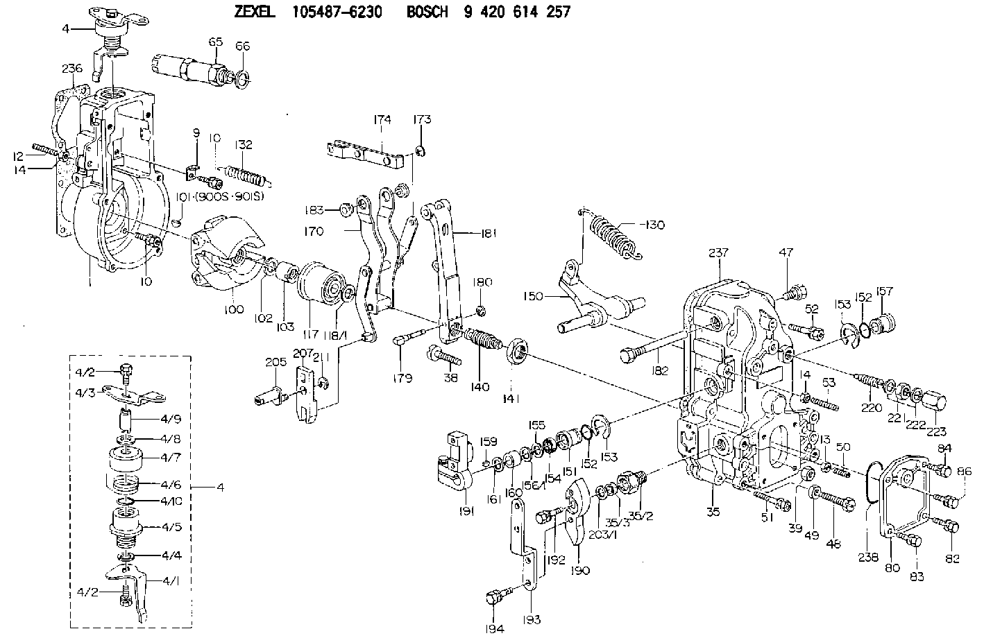
BOSCH
9 420 614 257
9420614257
ZEXEL
105487-6230
1054876230
Rating:
Scheme ###:
| 1. | [1] | 154000-4700 | GOVERNOR HOUSING |
| 4. | [1] | 154364-2420 | CONTROL LEVER |
| 4. | [1] | 154364-2420 | CONTROL LEVER |
| 4/1. | [1] | 154304-6200 | CONTROL LEVER |
| 4/2. | [2] | 154352-2000 | BLEEDER SCREW |
| 4/2. | [2] | 154352-2000 | BLEEDER SCREW |
| 4/3. | [1] | 154364-2400 | CONTROL LEVER |
| 4/4. | [1] | 029311-0230 | SHIM D18&10.3T0.5 |
| 4/5. | [1] | 154321-1500 | BUSHING |
| 4/6. | [1] | 154327-2901 | COILED SPRING |
| 4/7. | [1] | 154322-0100 | CAP |
| 4/8. | [1] | 029311-0220 | SHIM D18&10.3T0.2 |
| 4/9. | [1] | 154324-2700 | LEVER SHAFT |
| 4/10. | [1] | 029631-0030 | O-RING &9.8W2.3 |
| 9. | [1] | 154350-6000 | PLATE |
| 10. | [8] | 020106-2040 | BLEEDER SCREW M6P1L20 |
| 10. | [8] | 020106-2040 | BLEEDER SCREW M6P1L20 |
| 12. | [1] | 154010-0100 | FLAT-HEAD SCREW |
| 13. | [1] | 029240-6010 | UNION NUT M6P1.0H5* |
| 14. | [2] | 154011-0100 | HEXAGON NUT |
| 14. | [2] | 154011-0100 | HEXAGON NUT |
| 35. | [1] | 154513-1220 | GOVERNOR COVER |
| 35/2. | [1] | 154321-1800 | BUSHING |
| 35/3. | [1] | 029621-0080 | PACKING RING |
| 38. | [1] | 154031-3500 | FLAT-HEAD SCREW |
| 39. | [1] | 154011-1600 | UNION NUT |
| 47. | [1] | 154036-0300 | CAPSULE |
| 48. | [1] | 154010-5500 | BLEEDER SCREW M10P1.25L42 |
| 49. | [1] | 154011-2100 | UNION NUT |
| 50. | [1] | 155615-1100 | FLAT-HEAD SCREW M6P1.0L37 |
| 51. | [4] | 020106-3840 | BLEEDER SCREW |
| 52. | [2] | 020106-5040 | BLEEDER SCREW |
| 53. | [1] | 154010-0100 | FLAT-HEAD SCREW |
| 65. | [1] | 153043-6420 | STOPPING DEVICE |
| 66. | [1] | 026524-3040 | GASKET |
| 80. | [1] | 154060-4900 | COVER |
| 82. | [1] | 020006-1640 | BLEEDER SCREW M6P1L16 4T |
| 83. | [1] | 029020-6210 | BLEEDER SCREW |
| 84. | [1] | 020006-1640 | BLEEDER SCREW M6P1L16 4T |
| 86. | [1] | 029020-6210 | BLEEDER SCREW |
| 100. | [1] | 154100-9520 | FLYWEIGHT ASSEMBLY |
| 101. | [1] | 025803-1310 | WOODRUFF KEY |
| 102. | [1] | 029321-2020 | LOCKING WASHER |
| 103. | [1] | 029231-2030 | UNION NUT |
| 117. | [1] | 154123-2320 | SLIDING PIECE |
| 118/1. | [0] | 029311-0010 | SHIM D14&10.1T0.2 |
| 118/1. | [0] | 029311-0180 | SHIM D14&10.1T0.3 |
| 118/1. | [0] | 029311-0190 | SHIM D14&10.1T0.40 |
| 118/1. | [0] | 029311-0210 | SHIM D14&10.1T1 |
| 118/1. | [0] | 139410-0000 | SHIM D14.0&10.1T0.5 |
| 118/1. | [0] | 139410-0100 | SHIM D14.0&10.1T1.5 |
| 118/1. | [0] | 139410-3000 | SHIM D14&10.1T2.0 |
| 118/1. | [0] | 139410-3100 | SHIM D14&10.1T3.0 |
| 118/1. | [0] | 139410-3200 | SHIM D14&10.1T4.0 |
| 130. | [1] | 154150-6000 | GOVERNOR SPRING |
| 132. | [1] | 154154-4000 | COILED SPRING |
| 140. | [1] | 154178-7720 | HEADLESS SCREW |
| 141. | [1] | 029201-6010 | UNION NUT |
| 150. | [1] | 154200-3701 | SWIVELLING LEVER |
| 151. | [1] | 154204-2001 | BUSHING |
| 152. | [2] | 029631-8020 | O-RING |
| 152. | [2] | 029631-8020 | O-RING |
| 153. | [2] | 154354-3900 | LOCKING WASHER |
| 153. | [2] | 154354-3900 | LOCKING WASHER |
| 154. | [1] | 139611-0000 | PACKING RING |
| 155. | [1] | 139411-0000 | SHIM |
| 156/1. | [0] | 029311-1110 | SHIM D17&11T0.1 |
| 156/1. | [0] | 029311-1120 | SHIM D17&11T0.2 |
| 156/1. | [0] | 029311-1130 | SHIM D17&11T0.3 |
| 157. | [1] | 154204-3400 | BUSHING |
| 159. | [1] | 025803-1310 | WOODRUFF KEY |
| 160. | [1] | 154206-0900 | BUSHING |
| 161. | [0] | 154206-0200 | PLAIN WASHER D19.5&11.2T1.0 |
| 170. | [1] | 154211-7220 | FORK LEVER |
| 173. | [1] | 016010-0540 | LOCKING WASHER |
| 174. | [1] | 154230-4920 | STRAP |
| 179. | [1] | 154238-0301 | BEARING PIN |
| 180. | [1] | 016010-0540 | LOCKING WASHER |
| 181. | [1] | 154236-5300 | TENSIONING LEVER |
| 182. | [1] | 154237-0900 | BEARING PIN |
| 183. | [2] | 154237-0600 | BUSHING |
| 190. | [1] | 154360-2700 | CONTROL LEVER |
| 191. | [1] | 154340-0020 | CONTROL LEVER |
| 192. | [1] | 020006-1670 | BLEEDER SCREW M6P1L16 7T |
| 193. | [1] | 154386-0120 | CONTROL LEVER |
| 194. | [2] | 020006-1240 | BLEEDER SCREW M6P1L12 4T |
| 203/1. | [0] | 029311-0640 | SHIM D26.0&10.2T0.95 |
| 203/1. | [0] | 029311-0650 | SHIM D26.0&10.2T0.20 |
| 203/1. | [0] | 029311-0660 | SHIM D26.0&10.2T0.25 |
| 203/1. | [0] | 029311-0670 | SHIM D26.0&10.2T0.30 |
| 203/1. | [0] | 029311-0680 | SHIM D26.0&10.2T0.35 |
| 203/1. | [0] | 029311-0690 | SHIM D26.0&10.2T0.40 |
| 203/1. | [0] | 029311-0700 | SHIM D26.0&10.2T0.50 |
| 203/1. | [0] | 139410-1400 | SHIM D26&10.2T0.7 |
| 203/1. | [0] | 139410-1500 | SHIM D26&10.2T0.9 |
| 203/1. | [0] | 139410-1600 | SHIM D26&10.2T0.8 |
| 203/1. | [0] | 139410-2700 | SHIM D26&10.2T0.6 |
| 205. | [1] | 154324-3100 | LEVER SHAFT |
| 207. | [1] | 154326-0300 | CONTROL LEVER |
| 211. | [1] | 016010-0840 | LOCKING WASHER |
| 220. | [1] | 154050-6820 | HEADLESS SCREW |
| 221. | [1] | 029201-2130 | UNION NUT M12P1.0H6 |
| 222. | [2] | 026512-1540 | GASKET D15.4&12.2T1.50 |
| 223. | [1] | 154159-1200 | CAP NUT |
| 236. | [1] | 154371-5600 | GASKET |
| 237. | [1] | 154390-0300 | GASKET |
| 238. | [1] | 029635-2020 | O-RING |
| 900S. | [1] | 025803-1310 | WOODRUFF KEY |
| 901S. | [1] | 025803-1610 | WOODRUFF KEY |
Include in #1:
106651-4030
as GOVERNOR
Cross reference number
Zexel num
Bosch num
Firm num
Name
Information:
Illustration 1 g01068766
Inlet fuel line (fuel transfer pump to cylinder head) (1) Connector (2) Hose assembly (3) Fuel transfer pump
Remove connector (1) and hose assembly (2) from the fuel transfer pump (3). Refer to Illustration 1. Retain these parts for the reinstallation.
Illustration 2 g01068729
Outlet fuel line (fuel transfer pump to secondary fuel filter) (4) Adapter (5) Tee (6) Elbow (7) Hose assembly
Remove adapter (4), tee (5), elbow (6), and hose assembly (7) from the fuel transfer pump (3). Refer to Illustration 2. Retain these parts for the reinstallation.Note: Modifications to the tools may need to be made in order to reduce interference with engine components. Refer to Illustration 3.
Illustration 3 g01007381
Modified 2P-5494 crowfoot wrench
Illustration 4 g01068745
(3) Fuel transfer pump (8) Bolt (9) Bolt (10) Washer (11) Adapter (15) HEUI pump (21) Clip
Remove the bolt (8) and the clip (21) from the top of the fuel transfer pump. Refer to Illustration 4.
Remove the bolt (9) and the washer (10) from the bottom of the fuel transfer pump (3). Refer to Illustration 4.
Remove fuel transfer pump (3). Refer to Illustration 4.
Illustration 5 g01068776
(12) 45 ° adapter (13) Hose assembly (14) Straight connector (15) HEUI pump
Remove hose assembly (13) from 45 degree adapter (12) and straight connector (14) by using removal tool (A). Refer to Illustration 5.
Remove 45 degree adapter (12) from the HEUI pump (15). Remove straight adapter (14) from the cylinder head. Discard the parts. Refer to Illustration 5.Installation of the Engine Oil Lines Group
Illustration 6 g01068779
(16) 247-3755 Tube As (17) 6V-8636 Connector (18) 221-3494 O-Ring Seal (19) 214-7568 O-Ring Seal (20) 6V-8724 Elbow
Apply a light coat of oil to the O-rings (18) and (19) during installation. Install the O-ring (18) on