Information governor
BOSCH
9 420 611 998
9420611998
ZEXEL
105487-6080
1054876080
NISSAN-DIESEL
1910197378
1910197378
Rating:
Scheme ###:
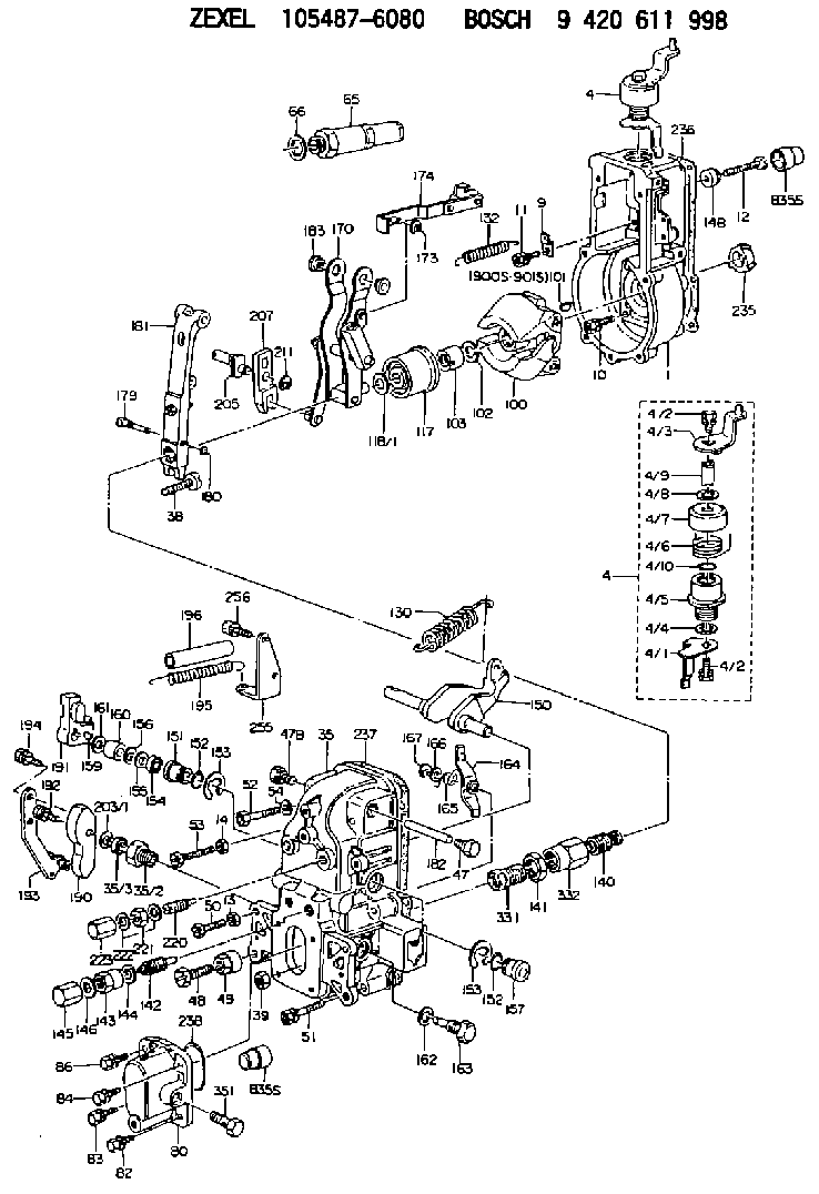
| 1. | [1] | 154004-0100 | GOVERNOR HOUSING |
| 4. | [1] | 154380-0521 | CONTROL LEVER |
| 4. | [1] | 154380-0521 | CONTROL LEVER |
| 4/1. | [1] | 154304-6200 | CONTROL LEVER |
| 4/2. | [2] | 154352-2000 | BLEEDER SCREW |
| 4/2. | [2] | 154352-2000 | BLEEDER SCREW |
| 4/3. | [1] | 154380-0511 | CONTROL LEVER |
| 4/4. | [1] | 029311-0230 | SHIM D18&10.3T0.5 |
| 4/5. | [1] | 154321-1500 | BUSHING |
| 4/6. | [1] | 154327-6701 | COILED SPRING |
| 4/7. | [1] | 154322-0100 | CAP |
| 4/8. | [1] | 029311-0220 | SHIM D18&10.3T0.2 |
| 4/9. | [1] | 154324-2700 | LEVER SHAFT |
| 4/10. | [1] | 029631-0030 | O-RING &9.8W2.3 |
| 9. | [1] | 154350-6000 | PLATE |
| 10. | [4] | 020106-2040 | BLEEDER SCREW M6P1L20 |
| 11. | [4] | 020106-1840 | BLEEDER SCREW M6P1L18 |
| 12. | [1] | 154010-8100 | BLEEDER SCREW M8P1.25L65 |
| 13. | [1] | 013020-6040 | UNION NUT M6P1H5 |
| 14. | [1] | 154011-0100 | HEXAGON NUT |
| 14B. | [1] | 154011-2300 | UNION NUT |
| 35. | [1] | 154515-4320 | GOVERNOR COVER |
| 35/2. | [1] | 154321-2900 | BUSHING |
| 35/3. | [1] | 139610-1100 | PACKING RING |
| 38. | [1] | 154031-3401 | FLAT-HEAD SCREW |
| 39. | [1] | 029201-0160 | UNION NUT |
| 47. | [1] | 154036-1800 | CAPSULE |
| 47B. | [1] | 154036-1900 | CAPSULE |
| 48. | [1] | 154010-7700 | BLEEDER SCREW M10P1.25L51 |
| 48B. | [1] | 154010-6000 | BLEEDER SCREW M10P1.25L55 |
| 49. | [1] | 154011-2200 | UNION NUT |
| 50. | [1] | 155615-1900 | BLEEDER SCREW |
| 51. | [5] | 020106-4540 | BLEEDER SCREW M6P1.0L45 |
| 52. | [2] | 029010-6850 | BLEEDER SCREW |
| 53. | [1] | 154010-3100 | BLEEDER SCREW |
| 54. | [2] | 014110-6440 | LOCKING WASHER |
| 65. | [1] | 153043-8020 | STOPPING DEVICE |
| 66. | [1] | 026524-3040 | GASKET |
| 80. | [1] | 154063-5620 | COVER |
| 82. | [1] | 020006-1640 | BLEEDER SCREW M6P1L16 4T |
| 83. | [1] | 029020-6210 | BLEEDER SCREW |
| 84. | [1] | 020006-1640 | BLEEDER SCREW M6P1L16 4T |
| 86. | [1] | 029020-6210 | BLEEDER SCREW |
| 100. | [1] | 154100-9220 | FLYWEIGHT ASSEMBLY |
| 101. | [1] | 025803-1310 | WOODRUFF KEY |
| 102. | [1] | 029321-2020 | LOCKING WASHER |
| 103. | [1] | 139212-0000 | UNION NUT |
| 117. | [1] | 154123-2320 | SLIDING PIECE |
| 118/1. | [0] | 029311-0010 | SHIM D14&10.1T0.2 |
| 118/1. | [0] | 029311-0180 | SHIM D14&10.1T0.3 |
| 118/1. | [0] | 029311-0190 | SHIM D14&10.1T0.40 |
| 118/1. | [0] | 029311-0210 | SHIM D14&10.1T1 |
| 118/1. | [0] | 139410-0000 | SHIM D14.0&10.1T0.5 |
| 118/1. | [0] | 139410-0100 | SHIM D14.0&10.1T1.5 |
| 118/1. | [0] | 139410-3000 | SHIM D14&10.1T2.0 |
| 118/1. | [0] | 139410-3100 | SHIM D14&10.1T3.0 |
| 118/1. | [0] | 139410-3200 | SHIM D14&10.1T4.0 |
| 130. | [1] | 154150-8300 | GOVERNOR SPRING |
| 132. | [1] | 154154-0200 | COILED SPRING |
| 140. | [1] | 154183-3220 | HEADLESS SCREW |
| 141. | [1] | 139218-0100 | UNION NUT |
| 142. | [1] | 154242-3320 | HEADLESS SCREW |
| 143. | [1] | 154242-3200 | UNION NUT |
| 144. | [1] | 026516-2040 | GASKET D19.9&16.2T1 |
| 145. | [1] | 154159-1800 | CAP NUT |
| 146. | [1] | 029331-6130 | GASKET |
| 150. | [1] | 154200-5801 | SWIVELLING LEVER |
| 151. | [1] | 154200-5501 | BUSHING |
| 152. | [2] | 139700-0000 | O-RING |
| 152. | [2] | 139700-0000 | O-RING |
| 153. | [2] | 154354-3900 | LOCKING WASHER |
| 153. | [2] | 154354-3900 | LOCKING WASHER |
| 154. | [1] | 139610-0101 | PACKING RING |
| 155. | [1] | 139411-0100 | SHIM D22.0&12.0T0.40 |
| 156. | [0] | 139411-0200 | SHIM D18.0&12.0T0.10 |
| 156B. | [0] | 139411-0300 | SHIM D18.0&12.0T0.20 |
| 156C. | [0] | 139411-0400 | SHIM D18.0&12.0T0.30 |
| 157. | [1] | 154204-3500 | BUSHING |
| 159. | [1] | 025803-1310 | WOODRUFF KEY |
| 160. | [1] | 154206-2300 | BUSHING |
| 161. | [0] | 154206-2400 | PLAIN WASHER D20.5&12.2T1 |
| 162. | [1] | 029331-6050 | GASKET |
| 163. | [1] | 154401-3201 | BLEEDER SCREW |
| 164. | [1] | 154243-0820 | CONTROL LEVER |
| 165. | [1] | 154327-6100 | COILED SPRING |
| 166. | [1] | 029310-8320 | SHIM D16.5&8T0.2 |
| 167. | [1] | 154356-3600 | LOCKING WASHER |
| 170. | [1] | 154216-1820 | FORK LEVER |
| 173. | [1] | 016010-0540 | LOCKING WASHER |
| 174. | [1] | 154230-6620 | STRAP |
| 179. | [1] | 154238-0201 | BEARING PIN |
| 180. | [1] | 016010-0540 | LOCKING WASHER |
| 181. | [1] | 154236-9321 | TENSIONING LEVER |
| 182. | [1] | 154237-1200 | BEARING PIN |
| 183. | [2] | 154237-1300 | BUSHING |
| 190. | [1] | 154360-2700 | CONTROL LEVER |
| 191. | [1] | 154340-1920 | CONTROL LEVER |
| 192. | [1] | 020006-1670 | BLEEDER SCREW M6P1L16 7T |
| 193. | [1] | 154369-7320 | CONTROL LEVER |
| 194. | [2] | 020006-1240 | BLEEDER SCREW M6P1L12 4T |
| 195. | [2] | 154317-8300 | COILED SPRING |
| 196. | [2] | 154156-3000 | TUBE |
| 203/1. | [0] | 139410-0200 | SHIM D32&10.2T0.1 |
| 203/1. | [0] | 139410-0300 | SHIM D32&10.2T0.3 |
| 203/1. | [0] | 139410-0400 | SHIM D32&10.2T0.5 |
| 203/1. | [0] | 139410-0500 | SHIM D32&10.2T0.9 |
| 205. | [1] | 154324-3400 | LEVER SHAFT |
| 207. | [1] | 154326-0300 | CONTROL LEVER |
| 211. | [1] | 016010-0840 | LOCKING WASHER |
| 220. | [1] | 154050-7720 | HEADLESS SCREW |
| 221. | [1] | 029201-2130 | UNION NUT M12P1.0H6 |
| 222. | [2] | 026512-1540 | GASKET D15.4&12.2T1.50 |
| 223. | [1] | 154159-1200 | CAP NUT |
| 235. | [1] | 155412-5200 | IMPELLER WHEEL |
| 236. | [1] | 154371-5600 | GASKET |
| 237. | [1] | 154390-0200 | GASKET |
| 238. | [1] | 139700-0100 | O-RING |
| 255. | [1] | 154372-6220 | BRACKET |
| 256. | [2] | 020006-1240 | BLEEDER SCREW M6P1L12 4T |
| 331. | [1] | 154179-9020 | HEADLESS SCREW |
| 332. | [1] | 139218-0500 | UNION NUT |
| 351. | [1] | 139812-0100 | EYE BOLT |
| 900S. | [1] | 025803-1310 | WOODRUFF KEY |
| 901S. | [1] | 025803-1610 | WOODRUFF KEY |
Cross reference number
Zexel num
Bosch num
Firm num
Name
105487-6080
1910197378 NISSAN-DIESEL
GOVERNOR
K 14JN MECHANICAL GOVERNOR GOV RFD GOV
K 14JN MECHANICAL GOVERNOR GOV RFD GOV
Information:
Table 2
Specifications for Valve Opening Pressure
Nozzle Assembly Valve Opening Pressure
1W-5829
10300 to 17690 kPa (1500 to 2505 psi)
4W-1819
4W-8483
7E-3969
7N-0449
7W-3710
7W-8043
9N-3979
101-0060
115-3354
122-9007
9L-7883
16560 to 17990 kPa (2400 to 2600 psi)
9L-9263
9N-2366
9L-6969
13090 to 19900 kPa (1900 2900 psi)
9N-3299
9N-3700 If the fuel nozzle is not within specifications, stop the test and do not use the nozzle.Check for Tip Leakage
Close the gauge protector valve (0 to 40,000 kPa (0 to 5,800 psi) gauge).
Flush the fuel nozzle that is being tested by pumping the tester for 3 full strokes.
Open the gauge protector valve (0 to 40,000 kPa (0 to 5,800 psi) gauge).
Use a clean cloth to dry the tip and the body of the fuel injector. All test fluid should be wiped from the nozzle assembly.
A clean cloth should be wrapped around the top of the fuel nozzle in order to absorb any internal return leakage.
Calculate the test pressure that will be used for the tip leakage test.Use the fuel nozzle's valve opening pressure, that has been previously recorded, in order to calculate the test pressure for the nozzle that is being tested.
Subtract a value of 1875 kPa (275 psi) from the valve opening pressure that was previously obtained.
Record the result of the calculation as the test pressure that will be used for the tip leakage test.
Slowly apply the test pressure, that has been calculated in Step 6, to the fuel nozzle.
Close the pump isolator valve.
Hold this test pressure for 10 seconds.
Count the number of drops of test fluid that drips from the nozzle during the duration of the test. Open the pump isolator valve in order to release the pressure on the fuel nozzle when the test is completed.Refer to the information that is provided in Table 3 in order to evaluate the results of the test.Note: Ensure that any test fluid that collects on the tip of the fuel nozzle is not fluid leakage from the test fixture.
Table 3
Specifications for Tip Leakage
(Leakage within 15 seconds after the test pressure is applied to the nozzle.)
Nozzle Assembly Maximum Leakage
1W-5829 20 drops (1)
4W-1819
4W-8483
7E-3969
7N-0449
7W-3710
7W-8043
9N-3979
101-0060
115-3354
122-9007
9L-7883 3 drops (1)
9L-9263
9N-2366
9L-6969 30 drops (1)
9N-3299
9N-3700
( 1 ) No minimum specificationIf the tip leakage for the fuel nozzle is not within specifications, stop the test and do not use the fuel nozzle.Test the Fuel Nozzle for Plugged Orifices
Illustration 2 g00923165
Spray patterns for pencil type fuel nozzles.
Close the gauge protector valve (0 to 40,000 kPa (0 to 5,800 psi) gauge).
Rapidly increase the pressure on the fuel nozzle until fluid sprays from the tip of the fuel nozzle.Note: For this test, each full