Information governor
BOSCH
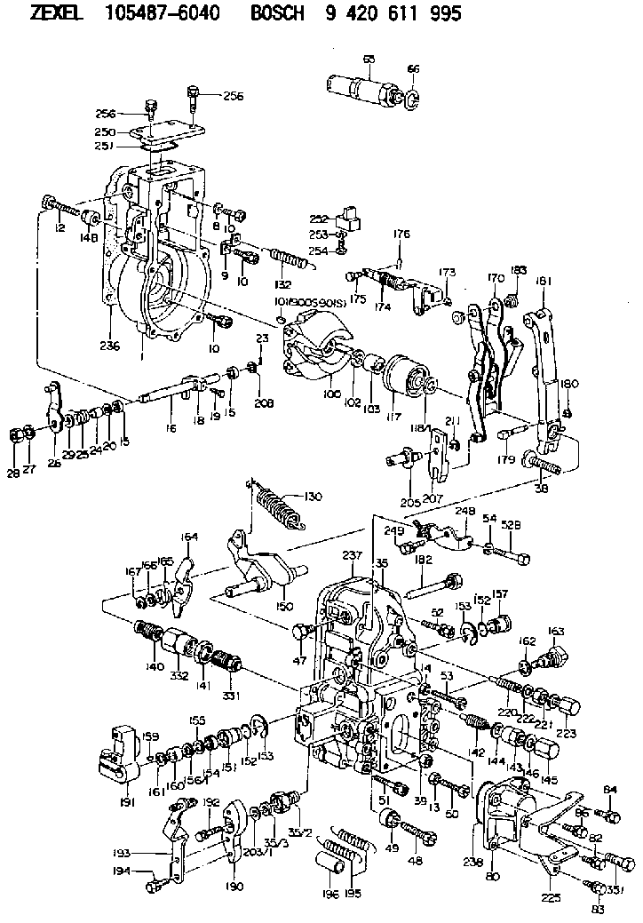
9 420 611 995
9420611995
ZEXEL
105487-6040
1054876040
NISSAN-DIESEL
1910196271
1910196271
Rating:
Scheme ###:
| 1. | [1] | 154004-2822 | GOVERNOR HOUSING |
| 8. | [1] | 139506-0100 | GASKET D12.0&6.2T1.0 |
| 9. | [1] | 154350-6000 | PLATE |
| 10. | [8] | 020106-2040 | BLEEDER SCREW M6P1L20 |
| 10. | [8] | 020106-2040 | BLEEDER SCREW M6P1L20 |
| 10. | [8] | 020106-2040 | BLEEDER SCREW M6P1L20 |
| 12. | [1] | 154010-7200 | BLEEDER SCREW M8P1.25L62 |
| 13. | [1] | 013020-6040 | UNION NUT M6P1H5 |
| 14. | [1] | 154011-0100 | HEXAGON NUT |
| 14B. | [1] | 154011-2300 | UNION NUT |
| 15. | [2] | 029620-8050 | PACKING RING |
| 15. | [2] | 029620-8050 | PACKING RING |
| 16. | [1] | 155004-3600 | LEVER SHAFT |
| 18. | [1] | 155003-2101 | CONTROL LEVER |
| 19. | [1] | 155006-0700 | BLEEDER SCREW |
| 20. | [1] | 139308-0900 | PLAIN WASHER D16&8T1 |
| 20B. | [1] | 139308-1000 | PLAIN WASHER D16&8T1.5 |
| 23. | [1] | 025520-1210 | SPLIT PIN |
| 24. | [1] | 154206-2000 | BUSHING |
| 25. | [1] | 154327-3600 | COILED SPRING |
| 26. | [1] | 154380-2021 | CONTROL LEVER |
| 27. | [1] | 014110-8440 | LOCKING WASHER |
| 28. | [1] | 013020-8040 | UNION NUT M8P1.25H7 |
| 29. | [1] | 139408-1400 | SHIM |
| 29B. | [0] | 139408-1400 | SHIM |
| 29C. | [0] | 139408-1500 | SHIM |
| 35. | [1] | 154515-4520 | GOVERNOR COVER |
| 35/2. | [1] | 154321-2300 | BUSHING |
| 35/3. | [1] | 139610-1100 | PACKING RING |
| 38. | [1] | 154031-3500 | FLAT-HEAD SCREW |
| 39. | [1] | 154011-1600 | UNION NUT |
| 47. | [1] | 154036-1200 | CAPSULE |
| 48. | [1] | 154010-7700 | BLEEDER SCREW M10P1.25L51 |
| 48B. | [1] | 154010-7100 | BLEEDER SCREW M10P1.25L47 |
| 49. | [1] | 154011-2200 | UNION NUT |
| 50. | [1] | 155615-1900 | BLEEDER SCREW |
| 51. | [4] | 020106-3840 | BLEEDER SCREW |
| 52. | [1] | 020106-5040 | BLEEDER SCREW |
| 52B. | [1] | 029010-6850 | BLEEDER SCREW |
| 53. | [1] | 154010-3100 | BLEEDER SCREW |
| 54. | [1] | 014110-6440 | LOCKING WASHER |
| 65. | [1] | 153043-8220 | STOPPING DEVICE |
| 66. | [1] | 026524-3040 | GASKET |
| 80. | [1] | 154063-4320 | COVER |
| 82. | [1] | 020006-1640 | BLEEDER SCREW M6P1L16 4T |
| 83. | [1] | 029020-6240 | BLEEDER SCREW |
| 84. | [1] | 020006-1840 | BLEEDER SCREW M6P1L18 |
| 86. | [1] | 029020-6240 | BLEEDER SCREW |
| 100. | [1] | 154100-9520 | FLYWEIGHT ASSEMBLY |
| 101. | [1] | 025803-1310 | WOODRUFF KEY |
| 102. | [1] | 029321-2020 | LOCKING WASHER |
| 103. | [1] | 029231-2030 | UNION NUT |
| 117. | [1] | 154123-2320 | SLIDING PIECE |
| 118/1. | [0] | 029311-0010 | SHIM D14&10.1T0.2 |
| 118/1. | [0] | 029311-0180 | SHIM D14&10.1T0.3 |
| 118/1. | [0] | 029311-0190 | SHIM D14&10.1T0.40 |
| 118/1. | [0] | 029311-0210 | SHIM D14&10.1T1 |
| 118/1. | [0] | 139410-0000 | SHIM D14.0&10.1T0.5 |
| 118/1. | [0] | 139410-0100 | SHIM D14.0&10.1T1.5 |
| 118/1. | [0] | 139410-3000 | SHIM D14&10.1T2.0 |
| 118/1. | [0] | 139410-3100 | SHIM D14&10.1T3.0 |
| 118/1. | [0] | 139410-3200 | SHIM D14&10.1T4.0 |
| 130. | [1] | 154150-7200 | GOVERNOR SPRING |
| 132. | [1] | 154154-0200 | COILED SPRING |
| 140. | [1] | 154180-5220 | HEADLESS SCREW |
| 141. | [1] | 029201-6010 | UNION NUT |
| 142. | [1] | 154242-4720 | HEADLESS SCREW |
| 143. | [1] | 154242-3200 | UNION NUT |
| 144. | [1] | 026516-2040 | GASKET D19.9&16.2T1 |
| 145. | [1] | 154159-1800 | CAP NUT |
| 146. | [1] | 029331-6130 | GASKET |
| 150. | [1] | 154200-3701 | SWIVELLING LEVER |
| 151. | [1] | 154204-2001 | BUSHING |
| 152. | [2] | 029631-8020 | O-RING |
| 152. | [2] | 029631-8020 | O-RING |
| 153. | [2] | 154354-3900 | LOCKING WASHER |
| 153. | [2] | 154354-3900 | LOCKING WASHER |
| 154. | [1] | 139611-0000 | PACKING RING |
| 155. | [1] | 139411-0000 | SHIM |
| 156/1. | [0] | 029311-1110 | SHIM D17&11T0.1 |
| 156/1. | [0] | 029311-1120 | SHIM D17&11T0.2 |
| 156/1. | [0] | 029311-1130 | SHIM D17&11T0.3 |
| 157. | [1] | 154204-3400 | BUSHING |
| 159. | [1] | 025803-1310 | WOODRUFF KEY |
| 160. | [1] | 154206-0900 | BUSHING |
| 161. | [0] | 154206-0200 | PLAIN WASHER D19.5&11.2T1.0 |
| 162. | [1] | 029331-6050 | GASKET |
| 163. | [1] | 154401-3401 | BLEEDER SCREW |
| 164. | [1] | 154243-0620 | CONTROL LEVER |
| 165. | [1] | 154327-5400 | COILED SPRING |
| 166. | [1] | 029310-8320 | SHIM D16.5&8T0.2 |
| 167. | [1] | 154356-3600 | LOCKING WASHER |
| 170. | [1] | 154211-7220 | FORK LEVER |
| 173. | [1] | 016010-0540 | LOCKING WASHER |
| 174. | [1] | 154235-0420 | STRAP |
| 175. | [1] | 159231-4900 | BEARING PIN |
| 176. | [1] | 155402-3800 | SAFETY PIN |
| 179. | [1] | 154238-0301 | BEARING PIN |
| 180. | [1] | 016010-0540 | LOCKING WASHER |
| 181. | [1] | 154236-7021 | TENSIONING LEVER |
| 182. | [1] | 154237-0900 | BEARING PIN |
| 183. | [2] | 154237-0600 | BUSHING |
| 190. | [1] | 154360-2700 | CONTROL LEVER |
| 191. | [1] | 154340-0020 | CONTROL LEVER |
| 192. | [1] | 020006-1670 | BLEEDER SCREW M6P1L16 7T |
| 193. | [1] | 154369-6920 | CONTROL LEVER |
| 194. | [2] | 020006-1240 | BLEEDER SCREW M6P1L12 4T |
| 195. | [2] | 154317-9300 | COILED SPRING |
| 196. | [2] | 154156-2900 | TUBE |
| 203/1. | [0] | 139410-0200 | SHIM D32&10.2T0.1 |
| 203/1. | [0] | 139410-0300 | SHIM D32&10.2T0.3 |
| 203/1. | [0] | 139410-0400 | SHIM D32&10.2T0.5 |
| 203/1. | [0] | 139410-0500 | SHIM D32&10.2T0.9 |
| 205. | [1] | 154324-3100 | LEVER SHAFT |
| 207. | [1] | 154326-0300 | CONTROL LEVER |
| 211. | [1] | 016010-0840 | LOCKING WASHER |
| 220. | [1] | 154050-6820 | HEADLESS SCREW |
| 221. | [1] | 029201-2130 | UNION NUT M12P1.0H6 |
| 222. | [2] | 026512-1540 | GASKET D15.4&12.2T1.50 |
| 223. | [1] | 154159-1200 | CAP NUT |
| 236. | [1] | 154371-5600 | GASKET |
| 237. | [1] | 154390-0300 | GASKET |
| 238. | [1] | 029635-2020 | O-RING |
| 248. | [1] | 154372-3220 | BRACKET |
| 249. | [1] | 020006-1240 | BLEEDER SCREW M6P1L12 4T |
| 250. | [1] | 154063-9800 | COVER |
| 251. | [1] | 154419-2500 | SEAL RING |
| 252. | [1] | 154232-2820 | CONNECTOR |
| 253. | [1] | 029320-5020 | LOCKING WASHER |
| 254. | [1] | 010535-1040 | FLAT-HEAD SCREW M5P0.8L10 |
| 255. | [1] | 154372-5920 | BRACKET |
| 256. | [4] | 020106-1640 | BLEEDER SCREW M6P1.0L14 |
| 256. | [4] | 020106-1640 | BLEEDER SCREW M6P1.0L14 |
| 331. | [1] | 154178-7620 | HEADLESS SCREW |
| 332. | [1] | 029201-6220 | UNION NUT |
| 351. | [1] | 027412-2440 | EYE BOLT |
| 900S. | [1] | 025803-1310 | WOODRUFF KEY |
| 901S. | [1] | 025803-1610 | WOODRUFF KEY |
Cross reference number
Zexel num
Bosch num
Firm num
Name
105487-6040
1910196271 NISSAN-DIESEL
GOVERNOR
K 14JN MECHANICAL GOVERNOR GOV RFD GOV
K 14JN MECHANICAL GOVERNOR GOV RFD GOV
Information:
Personal injury can result from being struck by parts propelled by a released spring force.Make sure to wear all necessary protective equipment.Follow the recommended procedure and use all recommended tooling to release the spring force.
Care must be taken to ensure that fluids are contained during performance of inspection, maintenance, testing, adjusting and repair of the product. Be prepared to collect the fluid with suitable containers before opening any compartment or disassembling any component containing fluids.Dispose of all fluids according to local regulations and mandates.
If possible, take the fuel injection pump to a clean work area.
Clean the outside surfaces of the fuel injection pump.
Illustration 1 g03117860
Typical example
Place a suitable container under the fuel injection pump to collect any fuel from the fuel injection pump. Use a suitable tool to loosen the drain plug (1). If necessary, retain the fuel collected for analysis if required.
Illustration 2 g03117878
Typical example
Use a suitable pair of pliers to remove the throttle return spring (2).Note: Care should be taken when the spring is removed.
Illustration 3 g03117896
Typical example
Loosen self-locking nut (3). Do not remove the nut.
Illustration 4 g03117916
Typical example
Use a suitable pair of pliers to lift and disconnect throttle spring (4). Remove self-locking nut (3), washer, upper retainer, spring, lower retainer, spacer, lever, and dust cap.Note: Care should be taken when the spring is removed.
Illustration 5 g03117938
Typical example
Remove four screws (6) in the governor cover (7). Gently push the throttle shaft (5) down into the cover (7).
Illustration 6 g03117956
Typical example
To inspect the internal components of the fuel injection pump, gently lift and rotate the cover (7).Note: The cover is still connected internally, if resistance is felt, lower the cover and move the cover backwards. Attempt to lift the cover again.
Inspect the internal components of the fuel injection pump. Refer to steps 9a and 9b.
Illustration 7 g03117961
Typical example
If good quality fuel is being used, the components will be clean. Refer to illustration 7. Take photographs of the identification plate of the fuel injection pump and any evidence found. Attach the photographs to support the claim story.
Illustration 8 g03118119
Typical example
Illustration 9 g03118121
Typical example
If the injection pump has been run with excessive water in the fuel, there will be signs of rust and oxidization of the steel components. Refer to illustration 8. Fuel with dirt ingress will show a build-up of dirt on the components. Refer to illustration 9.Note: Issues with the fuel injection pump that are due to dirt and water void Caterpillar warranty. Advise the customer on the correct fuel, maintenance, and fuel storage procedures. Refer to the relevant Operation and Maintenance Manual for more information.If the fuel injection pump shows signs that contaminated fuel is the root cause of the problem, the evidence can be shown to the customer immediately.After the fuel injection pump has been inspected, the fuel injection pump must not be used in service.Rebuild the fuel injection pump. Refer to steps 1 to 6
Lower the cover (7) back into position. Ensure the throttle shaft (5), has been returned to the original position.
Install the four screws (6) to the cover (7). Tighten the