Information governor
BOSCH
F 019 Z4E 873
f019z4e873
ZEXEL
105487-6021
1054876021
MITSUBISHI
ME731924
me731924
Rating:
Scheme ###:
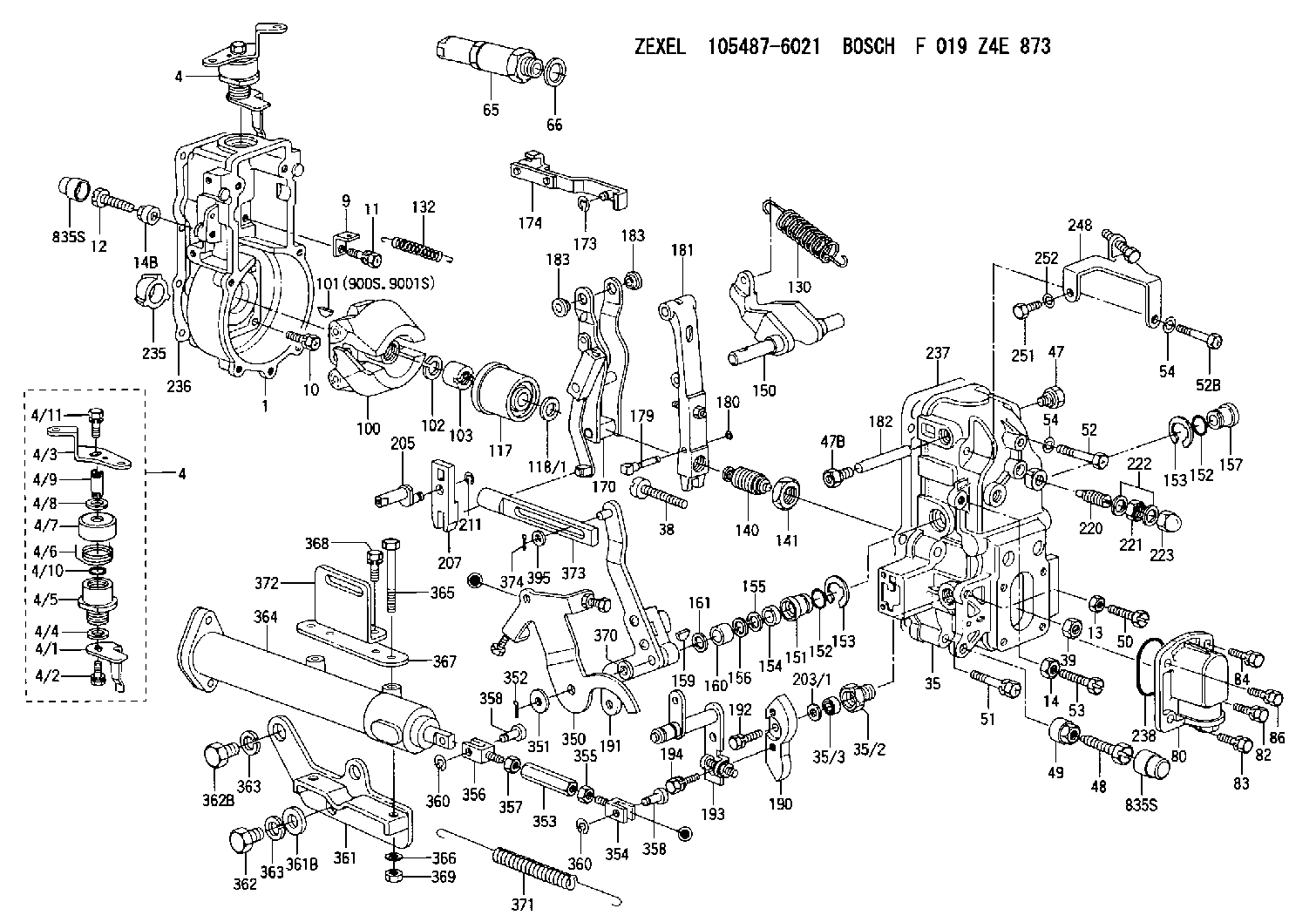
| 1. | [1] | 154004-0100 | GOVERNOR HOUSING |
| 4. | [1] | 154365-2220 | CONTROL LEVER |
| 4. | [1] | 154365-2220 | CONTROL LEVER |
| 4/1. | [1] | 154304-6200 | CONTROL LEVER |
| 4/2. | [1] | 154352-2000 | BLEEDER SCREW |
| 4/3. | [1] | 154365-2200 | CONTROL LEVER |
| 4/4. | [1] | 029311-0230 | SHIM D18&10.3T0.5 |
| 4/5. | [1] | 154321-1500 | BUSHING |
| 4/6. | [1] | 154327-6701 | COILED SPRING |
| 4/7. | [1] | 154322-0100 | CAP |
| 4/8. | [1] | 029311-0220 | SHIM D18&10.3T0.2 |
| 4/9. | [1] | 154324-2700 | LEVER SHAFT |
| 4/10. | [1] | 029631-0030 | O-RING &9.8W2.3 |
| 4/11. | [1] | 020006-1240 | BLEEDER SCREW M6P1L12 4T |
| 9. | [1] | 154350-6000 | PLATE |
| 10. | [4] | 020106-2040 | BLEEDER SCREW M6P1L20 |
| 11. | [4] | 020106-1840 | BLEEDER SCREW M6P1L18 |
| 12. | [1] | 154010-7400 | BLEEDER SCREW M8P1.25L55 |
| 13. | [1] | 013020-6040 | UNION NUT M6P1H5 |
| 14. | [1] | 013020-8040 | UNION NUT M8P1.25H7 |
| 14B. | [1] | 154011-2300 | UNION NUT |
| 35. | [1] | 154513-9820 | GOVERNOR COVER |
| 35/2. | [1] | 154321-2000 | BUSHING |
| 35/3. | [1] | 029621-0080 | PACKING RING |
| 38. | [1] | 154031-3401 | FLAT-HEAD SCREW |
| 39. | [1] | 029201-0160 | UNION NUT |
| 47. | [1] | 154036-1900 | CAPSULE |
| 47B. | [1] | 154036-1800 | CAPSULE |
| 48. | [1] | 154010-6000 | BLEEDER SCREW M10P1.25L55 |
| 48B. | [1] | 154010-7900 | BLEEDER SCREW M10P1.25L58 |
| 49. | [1] | 154011-2200 | UNION NUT |
| 50. | [1] | 155615-1900 | BLEEDER SCREW |
| 51. | [5] | 020106-4540 | BLEEDER SCREW M6P1.0L45 |
| 52. | [1] | 010006-6040 | BLEEDER SCREW |
| 52B. | [1] | 029010-6850 | BLEEDER SCREW |
| 53. | [1] | 154010-7400 | BLEEDER SCREW M8P1.25L55 |
| 54. | [2] | 014110-6440 | LOCKING WASHER |
| 54. | [2] | 014110-6440 | LOCKING WASHER |
| 65. | [1] | 153043-3120 | STOPPING DEVICE |
| 66. | [1] | 026524-3040 | GASKET |
| 80. | [1] | 154064-2520 | COVER |
| 82. | [1] | 020006-1640 | BLEEDER SCREW M6P1L16 4T |
| 83. | [1] | 029020-6210 | BLEEDER SCREW |
| 84. | [1] | 020006-1640 | BLEEDER SCREW M6P1L16 4T |
| 86. | [1] | 029020-6210 | BLEEDER SCREW |
| 100. | [1] | 154100-9220 | FLYWEIGHT ASSEMBLY |
| 101. | [1] | 025803-1310 | WOODRUFF KEY |
| 102. | [1] | 029321-2020 | LOCKING WASHER |
| 103. | [1] | 139212-0000 | UNION NUT |
| 117. | [1] | 154123-2320 | SLIDING PIECE |
| 118/1. | [0] | 029311-0010 | SHIM D14&10.1T0.2 |
| 118/1. | [0] | 029311-0180 | SHIM D14&10.1T0.3 |
| 118/1. | [0] | 029311-0190 | SHIM D14&10.1T0.40 |
| 118/1. | [0] | 029311-0210 | SHIM D14&10.1T1 |
| 118/1. | [0] | 139410-0000 | SHIM D14.0&10.1T0.5 |
| 118/1. | [0] | 139410-0100 | SHIM D14.0&10.1T1.5 |
| 118/1. | [0] | 139410-3000 | SHIM D14&10.1T2.0 |
| 118/1. | [0] | 139410-3100 | SHIM D14&10.1T3.0 |
| 118/1. | [0] | 139410-3200 | SHIM D14&10.1T4.0 |
| 130. | [1] | 154150-9400 | GOVERNOR SPRING |
| 132. | [1] | 154154-0200 | COILED SPRING |
| 140. | [1] | 154183-9020 | HEADLESS SCREW |
| 141. | [1] | 139218-0100 | UNION NUT |
| 150. | [1] | 154200-5601 | SWIVELLING LEVER |
| 151. | [1] | 154200-5501 | BUSHING |
| 152. | [2] | 139700-0000 | O-RING |
| 152. | [2] | 139700-0000 | O-RING |
| 153. | [2] | 154354-3900 | LOCKING WASHER |
| 153. | [2] | 154354-3900 | LOCKING WASHER |
| 154. | [1] | 139610-0101 | PACKING RING |
| 155. | [1] | 139411-0100 | SHIM D22.0&12.0T0.40 |
| 156. | [0] | 139411-0200 | SHIM D18.0&12.0T0.10 |
| 156B. | [0] | 139411-0300 | SHIM D18.0&12.0T0.20 |
| 156C. | [0] | 139411-0400 | SHIM D18.0&12.0T0.30 |
| 157. | [1] | 154204-3500 | BUSHING |
| 159. | [1] | 025803-1310 | WOODRUFF KEY |
| 160. | [1] | 154206-2300 | BUSHING |
| 161. | [0] | 154206-2400 | PLAIN WASHER D20.5&12.2T1 |
| 170. | [1] | 154216-1820 | FORK LEVER |
| 173. | [1] | 016010-0540 | LOCKING WASHER |
| 174. | [1] | 154230-6620 | STRAP |
| 179. | [1] | 154238-0201 | BEARING PIN |
| 180. | [1] | 016010-0540 | LOCKING WASHER |
| 181. | [1] | 154236-5200 | TENSIONING LEVER |
| 182. | [1] | 154237-1200 | BEARING PIN |
| 183. | [2] | 154237-1300 | BUSHING |
| 183. | [2] | 154237-1300 | BUSHING |
| 190. | [1] | 154360-2700 | CONTROL LEVER |
| 191. | [1] | 154395-2520 | CONTROL LEVER |
| 192. | [1] | 020006-1670 | BLEEDER SCREW M6P1L16 7T |
| 193. | [1] | 154368-5620 | CONTROL LEVER |
| 194. | [2] | 020006-1240 | BLEEDER SCREW M6P1L12 4T |
| 203/1. | [0] | 029311-0640 | SHIM D26.0&10.2T0.95 |
| 203/1. | [0] | 029311-0650 | SHIM D26.0&10.2T0.20 |
| 203/1. | [0] | 029311-0660 | SHIM D26.0&10.2T0.25 |
| 203/1. | [0] | 029311-0670 | SHIM D26.0&10.2T0.30 |
| 203/1. | [0] | 029311-0680 | SHIM D26.0&10.2T0.35 |
| 203/1. | [0] | 029311-0690 | SHIM D26.0&10.2T0.40 |
| 203/1. | [0] | 029311-0700 | SHIM D26.0&10.2T0.50 |
| 203/1. | [0] | 139410-1400 | SHIM D26&10.2T0.7 |
| 203/1. | [0] | 139410-1500 | SHIM D26&10.2T0.9 |
| 203/1. | [0] | 139410-1600 | SHIM D26&10.2T0.8 |
| 203/1. | [0] | 139410-2700 | SHIM D26&10.2T0.6 |
| 205. | [1] | 154324-3400 | LEVER SHAFT |
| 207. | [1] | 154326-0300 | CONTROL LEVER |
| 211. | [1] | 016010-0840 | LOCKING WASHER |
| 220. | [1] | 154050-3520 | HEADLESS SCREW |
| 221. | [1] | 029201-2130 | UNION NUT M12P1.0H6 |
| 222. | [2] | 026512-1540 | GASKET D15.4&12.2T1.50 |
| 223. | [1] | 154159-0100 | CAP NUT |
| 235. | [1] | 155412-5200 | IMPELLER WHEEL |
| 236. | [1] | 154371-5600 | GASKET |
| 237. | [1] | 154390-0200 | GASKET |
| 238. | [1] | 139700-0100 | O-RING |
| 248. | [1] | 154357-9720 | BRACKET |
| 251. | [1] | 010065-1240 | BLEEDER SCREW M5P0.8L12 |
| 252. | [1] | 014110-5440 | LOCKING WASHER |
| 350. | [1] | 154372-7920 | CONTROL LEVER |
| 351. | [2] | 014011-0140 | PLAIN WASHER D22&10.5T1.6 |
| 352. | [1] | 015320-1540 | SPLIT PIN |
| 353. | [1] | 154351-9200 | UNION NUT M6P1H40 |
| 353B. | [1] | 154354-3800 | UNION NUT M6P1H30 |
| 354. | [1] | 154373-2700 | CLEVIS |
| 355. | [1] | 013020-6040 | UNION NUT M6P1H5 |
| 356. | [1] | 154373-2800 | CLEVIS |
| 357. | [1] | 029200-6210 | UNION NUT |
| 358. | [2] | 154373-2900 | BEARING PIN |
| 358. | [2] | 154373-2900 | BEARING PIN |
| 360. | [2] | 016010-0640 | LOCKING WASHER |
| 360. | [2] | 016010-0640 | LOCKING WASHER |
| 361. | [1] | 154374-1220 | BRACKET |
| 361B. | [1] | 139316-0100 | PLAIN WASHER |
| 362. | [2] | 139016-0400 | BLEEDER SCREW |
| 362B. | [1] | 029001-6050 | BLEEDER SCREW |
| 363. | [3] | 014111-6440 | LOCKING WASHER |
| 363. | [3] | 014111-6440 | LOCKING WASHER |
| 364. | [1] | 154354-6120 | CONTROL CYLINDER |
| 365. | [2] | 010110-8040 | BLEEDER SCREW |
| 366. | [2] | 014111-0440 | LOCKING WASHER |
| 367. | [1] | 154372-7600 | PLATE |
| 368. | [2] | 020106-1040 | BLEEDER SCREW M6P1L12 |
| 369. | [2] | 013121-0040 | UNION NUT M10P1.25H8 |
| 370. | [0] | 029311-0570 | SHIM D20.8&10.3T0.5 |
| 371. | [1] | 154317-1500 | COILED SPRING |
| 372. | [1] | 154374-1300 | BRACKET |
| 373. | [1] | 154352-4700 | STRAP |
| 374. | [1] | 154373-4500 | SAFETY PIN |
| 395. | [0] | 029310-7010 | SHIM D14.5&7T0.1 |
| 395A. | [0] | 029310-7020 | SHIM D14.5&7T0.3 |
| 395B. | [0] | 029310-7030 | SHIM D14.5&7T0.5 |
| 835S. | [2] | 154062-1700 | CAP D20L32 |
| 835S. | [2] | 154062-1700 | CAP D20L32 |
| 900S. | [1] | 025803-1310 | WOODRUFF KEY |
| 901S. | [1] | 025803-1610 | WOODRUFF KEY |
Cross reference number
Zexel num
Bosch num
Firm num
Name
Information:
The 169-3374 Injector Sleeve Removal Group is used to remove the brass injector sleeves on 3176 and 3176B Engines, only. This tool group is used with the 9U-6860 Sleeve Replacement Group . The tool group eliminates the tapping and threading operation of the current 9U-6860 Sleeve Replacement Group . The benefits of this method of sleeve removal are easier sleeve removal and little debris that could enter the engine. This tool group uses a crimping die and captured stud similar to the current 3100 Sleeve Removal Tool. This tool group can be used with the cylinder head either on or off the engine.Additional Contact Information
For additional product support questions concerning this tool, contact the Dealer Service Tools Hotline at:USA: 1-800-542-8665, Option 1International: 1-309-578-7372Injector Sleeve Removal
Remove the rocker arms from the cylinder being repaired.
Remove the injector.
Illustration 4 g02888499
Put Sleeve Stud (3) into Injector Sleeve
Drop 142-8280 Sleeve Stud (3) into the injector sleeve and ensure that stud is resting at the bottom of the injector sleeve. The flat disc part of the sleeve stud should be below the top edge of the brass sleeve.
Illustration 5 g02888500
Insert Crimping Swage (9) Into Bore And Over Sleeve Stud (3)
Apply a light coating of grease to the inside cutting edge of crimping swage (9) and insert into the injector bore. Make sure that the tool is resting on the top edge of the brass sleeve by turning or "wiggling" slightly. It is possible for the tool to rest on the casting ledge (indicated by the arrow) in the cylinder head. The threads of sleeve stud (3) should go into the center hole of crimping swage (9), as shown in Figure 5.
Illustration 6 g02888508
Drive Crimping Swage (9) Down Into Injector Sleeve
Using a large hammer, strike the top of crimping swage (9) firmly and squarely. Drive down into the injector bore until the bottom slot is level with the top deck of the cylinder head, as shown in Figure 6.
Illustration 7 g02888509
Remove Driving Swage (9) With Crows Foot Pry Bar (12)
Remove the crimping swage from the injector bore. If the tool is stuck in the bore, use a crows foot pry bar (12) in the slot to work out the tool. Many times there will be a small amount of brass caught between crimping swage (9) and the injector bore causing the tool to stick. When the tool is removed, the top of the brass sleeve should be rolled over, trapping sleeve stud (3) inside the injector sleeve.Note: The sharp edge of crimping swage (9) must remain sharp and free of nicks or damage. This tool may be resharpened only on the inside cutting edge. Any sharpening procedure that reduces the OD of the cutting edge will result in poor tool performance and tool sticking.
Illustration 8 g02888517
Insert Sleeve Jaw (4)
Insert 151-4833 Sleeve Jaw (4) into the injector bore. The sharp edge of the sleeve jaw is designed to lock the rolled-over brass material between the sleeve stud and the sleeve jaw. The sleeve stud is then prevented from