Information governor
BOSCH
9 420 613 825
9420613825
ZEXEL
105487-5681
1054875681
MITSUBISHI
ME731920
me731920
Rating:
Scheme ###:
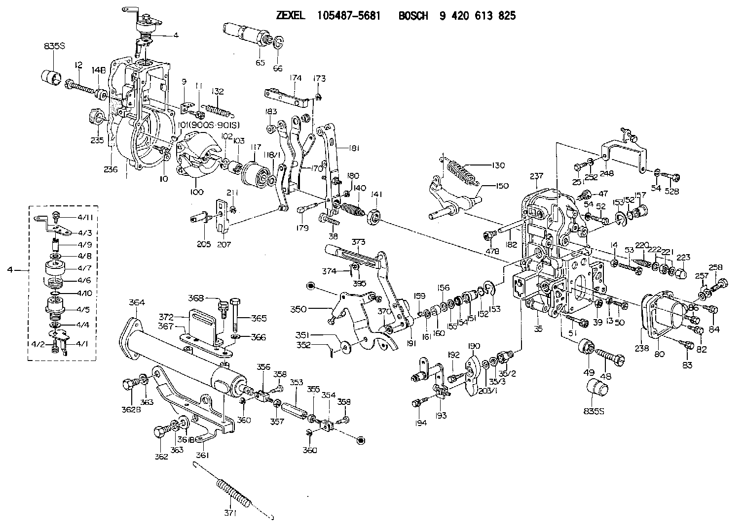
| 1. | [1] | 154004-0100 | GOVERNOR HOUSING |
| 4. | [1] | 154365-2220 | CONTROL LEVER |
| 4. | [1] | 154365-2220 | CONTROL LEVER |
| 4/1. | [1] | 154304-6200 | CONTROL LEVER |
| 4/2. | [1] | 154352-2000 | BLEEDER SCREW |
| 4/3. | [1] | 154365-2200 | CONTROL LEVER |
| 4/4. | [1] | 029311-0230 | SHIM D18&10.3T0.5 |
| 4/5. | [1] | 154321-1500 | BUSHING |
| 4/6. | [1] | 154327-6701 | COILED SPRING |
| 4/7. | [1] | 154322-0100 | CAP |
| 4/8. | [1] | 029311-0220 | SHIM D18&10.3T0.2 |
| 4/9. | [1] | 154324-2700 | LEVER SHAFT |
| 4/10. | [1] | 029631-0030 | O-RING &9.8W2.3 |
| 4/11. | [1] | 020006-1240 | BLEEDER SCREW M6P1L12 4T |
| 9. | [1] | 154350-6000 | PLATE |
| 10. | [4] | 020106-2040 | BLEEDER SCREW M6P1L20 |
| 11. | [4] | 020106-1840 | BLEEDER SCREW M6P1L18 |
| 12. | [1] | 154010-7400 | BLEEDER SCREW M8P1.25L55 |
| 13. | [1] | 013020-6040 | UNION NUT M6P1H5 |
| 14. | [1] | 013020-8040 | UNION NUT M8P1.25H7 |
| 14B. | [1] | 154011-2300 | UNION NUT |
| 35. | [1] | 154513-1020 | GOVERNOR COVER |
| 35/2. | [1] | 154321-2000 | BUSHING |
| 35/3. | [1] | 029621-0080 | PACKING RING |
| 38. | [1] | 154031-3401 | FLAT-HEAD SCREW |
| 39. | [1] | 029201-0160 | UNION NUT |
| 47. | [1] | 154036-1900 | CAPSULE |
| 47B. | [1] | 154036-1800 | CAPSULE |
| 48. | [1] | 154010-6000 | BLEEDER SCREW M10P1.25L55 |
| 48B. | [1] | 154010-7900 | BLEEDER SCREW M10P1.25L58 |
| 49. | [1] | 154011-2200 | UNION NUT |
| 50. | [1] | 155615-1900 | BLEEDER SCREW |
| 51. | [5] | 020106-4540 | BLEEDER SCREW M6P1.0L45 |
| 52. | [1] | 010006-6040 | BLEEDER SCREW |
| 52B. | [1] | 029010-6850 | BLEEDER SCREW |
| 53. | [1] | 154010-7400 | BLEEDER SCREW M8P1.25L55 |
| 54. | [2] | 014110-6440 | LOCKING WASHER |
| 54. | [2] | 014110-6440 | LOCKING WASHER |
| 65. | [1] | 153020-4320 | STOPPING DEVICE |
| 66. | [1] | 026524-3040 | GASKET |
| 80. | [1] | 154063-6521 | COVER |
| 82. | [1] | 020006-1640 | BLEEDER SCREW M6P1L16 4T |
| 83. | [1] | 029020-6210 | BLEEDER SCREW |
| 84. | [1] | 020006-1640 | BLEEDER SCREW M6P1L16 4T |
| 86. | [1] | 029020-6210 | BLEEDER SCREW |
| 100. | [1] | 154100-9220 | FLYWEIGHT ASSEMBLY |
| 101. | [1] | 025803-1310 | WOODRUFF KEY |
| 102. | [1] | 029321-2020 | LOCKING WASHER |
| 103. | [1] | 139212-0000 | UNION NUT |
| 117. | [1] | 154123-2320 | SLIDING PIECE |
| 118/1. | [0] | 029311-0010 | SHIM D14&10.1T0.2 |
| 118/1. | [0] | 029311-0180 | SHIM D14&10.1T0.3 |
| 118/1. | [0] | 029311-0190 | SHIM D14&10.1T0.40 |
| 118/1. | [0] | 029311-0210 | SHIM D14&10.1T1 |
| 118/1. | [0] | 139410-0000 | SHIM D14.0&10.1T0.5 |
| 118/1. | [0] | 139410-0100 | SHIM D14.0&10.1T1.5 |
| 118/1. | [0] | 139410-3000 | SHIM D14&10.1T2.0 |
| 118/1. | [0] | 139410-3100 | SHIM D14&10.1T3.0 |
| 118/1. | [0] | 139410-3200 | SHIM D14&10.1T4.0 |
| 130. | [1] | 154150-9400 | GOVERNOR SPRING |
| 132. | [1] | 154154-0200 | COILED SPRING |
| 140. | [1] | 154183-5820 | HEADLESS SCREW |
| 141. | [1] | 139218-0100 | UNION NUT |
| 150. | [1] | 154200-5601 | SWIVELLING LEVER |
| 151. | [1] | 154200-5501 | BUSHING |
| 152. | [2] | 139700-0000 | O-RING |
| 152. | [2] | 139700-0000 | O-RING |
| 153. | [2] | 154354-3900 | LOCKING WASHER |
| 153. | [2] | 154354-3900 | LOCKING WASHER |
| 154. | [1] | 139610-0101 | PACKING RING |
| 155. | [1] | 139411-0100 | SHIM D22.0&12.0T0.40 |
| 156. | [0] | 139411-0200 | SHIM D18.0&12.0T0.10 |
| 156B. | [0] | 139411-0300 | SHIM D18.0&12.0T0.20 |
| 156C. | [0] | 139411-0400 | SHIM D18.0&12.0T0.30 |
| 157. | [1] | 154204-3500 | BUSHING |
| 159. | [1] | 025803-1310 | WOODRUFF KEY |
| 160. | [1] | 154206-2300 | BUSHING |
| 161. | [0] | 154206-2400 | PLAIN WASHER D20.5&12.2T1 |
| 170. | [1] | 154216-1820 | FORK LEVER |
| 173. | [1] | 016010-0540 | LOCKING WASHER |
| 174. | [1] | 154230-6620 | STRAP |
| 179. | [1] | 154238-0201 | BEARING PIN |
| 180. | [1] | 016010-0540 | LOCKING WASHER |
| 181. | [1] | 154236-5200 | TENSIONING LEVER |
| 182. | [1] | 154237-1200 | BEARING PIN |
| 183. | [2] | 154237-1300 | BUSHING |
| 190. | [1] | 154360-2700 | CONTROL LEVER |
| 191. | [1] | 154395-2520 | CONTROL LEVER |
| 192. | [1] | 020006-1670 | BLEEDER SCREW M6P1L16 7T |
| 193. | [1] | 154368-5620 | CONTROL LEVER |
| 194. | [2] | 020006-1240 | BLEEDER SCREW M6P1L12 4T |
| 203/1. | [0] | 029311-0640 | SHIM D26.0&10.2T0.95 |
| 203/1. | [0] | 029311-0650 | SHIM D26.0&10.2T0.20 |
| 203/1. | [0] | 029311-0660 | SHIM D26.0&10.2T0.25 |
| 203/1. | [0] | 029311-0670 | SHIM D26.0&10.2T0.30 |
| 203/1. | [0] | 029311-0680 | SHIM D26.0&10.2T0.35 |
| 203/1. | [0] | 029311-0690 | SHIM D26.0&10.2T0.40 |
| 203/1. | [0] | 029311-0700 | SHIM D26.0&10.2T0.50 |
| 203/1. | [0] | 139410-1400 | SHIM D26&10.2T0.7 |
| 203/1. | [0] | 139410-1500 | SHIM D26&10.2T0.9 |
| 203/1. | [0] | 139410-1600 | SHIM D26&10.2T0.8 |
| 203/1. | [0] | 139410-2700 | SHIM D26&10.2T0.6 |
| 205. | [1] | 154324-3400 | LEVER SHAFT |
| 207. | [1] | 154326-0300 | CONTROL LEVER |
| 211. | [1] | 016010-0840 | LOCKING WASHER |
| 220. | [1] | 154050-3520 | HEADLESS SCREW |
| 221. | [1] | 029201-2130 | UNION NUT M12P1.0H6 |
| 222. | [2] | 026512-1540 | GASKET D15.4&12.2T1.50 |
| 223. | [1] | 154159-0100 | CAP NUT |
| 235. | [1] | 155412-5200 | IMPELLER WHEEL |
| 236. | [1] | 154371-5600 | GASKET |
| 237. | [1] | 154390-0200 | GASKET |
| 238. | [1] | 139700-0100 | O-RING |
| 248. | [1] | 154357-9720 | BRACKET |
| 251. | [1] | 010065-1240 | BLEEDER SCREW M5P0.8L12 |
| 252. | [1] | 014110-5440 | LOCKING WASHER |
| 257. | [2] | 026512-1840 | GASKET D17.9&12.2T1.50 |
| 258. | [1] | 153556-4800 | EYE BOLT |
| 350. | [1] | 154373-8720 | CONTROL LEVER |
| 351. | [2] | 014011-0140 | PLAIN WASHER D22&10.5T1.6 |
| 352. | [1] | 015320-1540 | SPLIT PIN |
| 353. | [1] | 154351-9200 | UNION NUT M6P1H40 |
| 353B. | [1] | 154354-3800 | UNION NUT M6P1H30 |
| 354. | [1] | 154373-2700 | CLEVIS |
| 355. | [1] | 013020-6040 | UNION NUT M6P1H5 |
| 356. | [1] | 154373-2800 | CLEVIS |
| 357. | [1] | 029200-6210 | UNION NUT |
| 358. | [2] | 154373-2900 | BEARING PIN |
| 358. | [2] | 154373-2900 | BEARING PIN |
| 360. | [2] | 016010-0640 | LOCKING WASHER |
| 360. | [2] | 016010-0640 | LOCKING WASHER |
| 361. | [1] | 154372-7520 | BRACKET |
| 361B. | [1] | 139316-0100 | PLAIN WASHER |
| 362. | [2] | 139016-0400 | BLEEDER SCREW |
| 362B. | [1] | 029001-6050 | BLEEDER SCREW |
| 363. | [3] | 014111-6440 | LOCKING WASHER |
| 363. | [3] | 014111-6440 | LOCKING WASHER |
| 364. | [1] | 154354-6120 | CONTROL CYLINDER |
| 365. | [2] | 010110-8040 | BLEEDER SCREW |
| 366. | [2] | 014111-0440 | LOCKING WASHER |
| 367. | [1] | 154372-7600 | PLATE |
| 368. | [2] | 020106-1040 | BLEEDER SCREW M6P1L12 |
| 370. | [0] | 029311-0570 | SHIM D20.8&10.3T0.5 |
| 371. | [1] | 154317-1500 | COILED SPRING |
| 372. | [1] | 154372-7400 | BRACKET |
| 373. | [1] | 154352-4700 | STRAP |
| 374. | [1] | 154373-4500 | SAFETY PIN |
| 395. | [0] | 029310-7010 | SHIM D14.5&7T0.1 |
| 395A. | [0] | 029310-7020 | SHIM D14.5&7T0.3 |
| 395B. | [0] | 029310-7030 | SHIM D14.5&7T0.5 |
| 900S. | [1] | 025803-1310 | WOODRUFF KEY |
| 901S. | [1] | 025803-1610 | WOODRUFF KEY |
Include in #1:
106873-2590
as GOVERNOR
Cross reference number
Zexel num
Bosch num
Firm num
Name
105487-5681
ME731920 MITSUBISHI
GOVERNOR
K 14JN MECHANICAL GOVERNOR GOV RFD GOV
K 14JN MECHANICAL GOVERNOR GOV RFD GOV
Information:
Parts Location
Illustration 2 g01601433
(1) 308-4943 Diesel Particulate Filter Group (2) 235-3963 Clamp Assembly (3) 308-4945 Bracket Assembly (4) 8T-4183 Bolt (5) 5P-8245 Hard Washer (6) 241-9265 Muffler Clamp Installation Procedure
Diesel Particulate Filter Installation
Illustration 3 g01606937
Typical Example (11) Existing muffler assembly (12) Existing bracket assembly (13) Support Assembly (14) Muffler Clamp (15) Tube assembly (16) Engine lifting plate (17) Bolt (18) Hard washer (19) Bolt
Remove existing muffler assembly (11) and bracket assembly (12). Set aside the three 8T-4183 Bolts (17), the five 8T-4184 Bolts (19) and the eight 5P-1076 Hard Washers (18). These parts will be reused in Steps 2 and 3. Refer to Illustration 3.
Illustration 4 g01601354
(3) 308-4945 Bracket Assembly (17) Bolt (18) Hard washer
Install 308-4945 Bracket Assembly (3) onto support assembly (13) by reusing three bolts (17) and three hard washers (18) that were removed in Step 1. Refer to Illustrations 3 and 4.
Illustration 5 g01601373
(19) Bolt
Reuse five bolts (19) and five hard washers (18) removed in Step 1 to secure bracket assembly (3) to engine lifting plate (16). Refer to Illustrations 3 and 5.
Illustration 6 g01601413
(2) 235-3963 Clamp Assembly (Lower half) (4) 8T-4183 Bolt (5) 5P-8245 Hard Washer
Remove the two bolts, two hard washers, two lock washers, and two nuts from each 235-3963 Clamp Assembly (2). Keep these parts together with the upper half of clamp assembly (2). These parts will be reinstalled in Step 8.
Install the lower half of 235-3963 Clamp Assembly (2) by using two 8T-4183 Bolts (4) and two 5P-8245 Hard Washers (5). Loosely secure these bolts so that the clamp assembly is adjustable. Repeat for the other clamp assembly (2). Refer to Illustration 6.
Illustration 7 g01601473
(1) 308-4943 Diesel Particulate Filter Gp
Install 308-4943 Diesel Particulate Filter Group (1) onto the lower halves of clamp assemblies (2). The weight of the diesel particulate filter group is approximately 40 kg (88 lb). Make sure that the inlet tube (not shown) of the inlet module of the diesel particulate filter fits into tube assembly (15). Use a new 241-9265 Muffler Clamp (6) to secure the connection. Refer to Illustrations 3 and 7.
Illustration 8 g01601333
(2) 235-3963 Clamp Assembly (Upper half) (2a) Bolt (2b) Hard washer (2c) Lock washer (2d) Nut
Once you have properly installed the tube assembly, tighten both bolts (4) to secure the bottom half of clamp assembly (2). Repeat for the other clamp assembly (4). Install the upper half of clamp assembly (2) by using two bolts (2a) and two hard washers (2b) through the upper clamp assembly, and two lock washers (2c) and two nuts (2d) on the lower clamp assembly. Repeat for the other clamp assembly. Refer to Illustration 8.
Reconnect the drain lines.Exhaust Monitor Installation
Refer to Special Instruction, REHS5606, "Installation and Operation of the Exhaust Monitor Used in All Diesel Particulate Filter (DPF) Retrofit Emissions Applications" for information regarding the installation and the operation of the exhaust monitor.The exhaust