Information governor
BOSCH
9 420 614 160
9420614160
ZEXEL
105487-5340
1054875340

Rating:
Scheme ###:
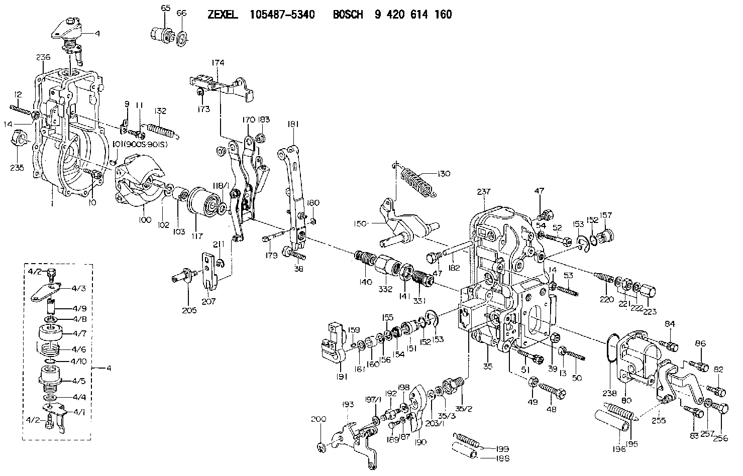
| 1. | [1] | 154004-4800 | GOVERNOR HOUSING |
| 4. | [1] | 154380-0720 | CONTROL LEVER |
| 4. | [1] | 154380-0720 | CONTROL LEVER |
| 4/1. | [1] | 154304-6200 | CONTROL LEVER |
| 4/2. | [2] | 154352-2000 | BLEEDER SCREW |
| 4/2. | [2] | 154352-2000 | BLEEDER SCREW |
| 4/3. | [1] | 154366-6600 | CONTROL LEVER |
| 4/4. | [1] | 029311-0230 | SHIM D18&10.3T0.5 |
| 4/5. | [1] | 154321-1500 | BUSHING |
| 4/6. | [1] | 154327-2901 | COILED SPRING |
| 4/7. | [1] | 154322-0100 | CAP |
| 4/8. | [1] | 029311-0220 | SHIM D18&10.3T0.2 |
| 4/9. | [1] | 154324-2700 | LEVER SHAFT |
| 4/10. | [1] | 139710-0500 | O-RING |
| 9. | [1] | 154353-5601 | PLATE |
| 10. | [4] | 020106-2040 | BLEEDER SCREW M6P1L20 |
| 11. | [4] | 020106-1840 | BLEEDER SCREW M6P1L18 |
| 12. | [1] | 154010-0100 | FLAT-HEAD SCREW |
| 13. | [1] | 029240-6010 | UNION NUT M6P1.0H5* |
| 14. | [2] | 154011-0100 | HEXAGON NUT |
| 14. | [2] | 154011-0100 | HEXAGON NUT |
| 35. | [1] | 154515-1420 | GOVERNOR COVER |
| 35/2. | [1] | 154321-2000 | BUSHING |
| 35/3. | [1] | 139610-0900 | PACKING RING |
| 38. | [1] | 154031-3401 | FLAT-HEAD SCREW |
| 39. | [1] | 029201-0160 | UNION NUT |
| 47. | [2] | 154036-2000 | CAPSULE |
| 47. | [2] | 154036-2000 | CAPSULE |
| 48. | [1] | 154010-5500 | BLEEDER SCREW M10P1.25L42 |
| 49. | [1] | 154011-2100 | UNION NUT |
| 50. | [1] | 155615-2300 | FLAT-HEAD SCREW |
| 51. | [5] | 020106-4540 | BLEEDER SCREW M6P1.0L45 |
| 52. | [2] | 029010-6850 | BLEEDER SCREW |
| 53. | [1] | 154010-0100 | FLAT-HEAD SCREW |
| 54. | [2] | 014110-6440 | LOCKING WASHER |
| 65. | [1] | 153021-5000 | CAP |
| 66. | [1] | 026524-3040 | GASKET |
| 80. | [1] | 154064-0700 | COVER |
| 82. | [1] | 020006-1640 | BLEEDER SCREW M6P1L16 4T |
| 83. | [1] | 029020-6240 | BLEEDER SCREW |
| 84. | [1] | 020006-1640 | BLEEDER SCREW M6P1L16 4T |
| 86. | [1] | 029020-6240 | BLEEDER SCREW |
| 100. | [1] | 154100-9220 | FLYWEIGHT ASSEMBLY |
| 101. | [1] | 025803-1310 | WOODRUFF KEY |
| 102. | [1] | 029321-2020 | LOCKING WASHER |
| 103. | [1] | 139212-0000 | UNION NUT |
| 117. | [1] | 154123-2320 | SLIDING PIECE |
| 118/1. | [0] | 029311-0010 | SHIM D14&10.1T0.2 |
| 118/1. | [0] | 029311-0180 | SHIM D14&10.1T0.3 |
| 118/1. | [0] | 029311-0190 | SHIM D14&10.1T0.40 |
| 118/1. | [0] | 029311-0210 | SHIM D14&10.1T1 |
| 118/1. | [0] | 139410-0000 | SHIM D14.0&10.1T0.5 |
| 118/1. | [0] | 139410-0100 | SHIM D14.0&10.1T1.5 |
| 118/1. | [0] | 139410-3000 | SHIM D14&10.1T2.0 |
| 118/1. | [0] | 139410-3100 | SHIM D14&10.1T3.0 |
| 118/1. | [0] | 139410-3200 | SHIM D14&10.1T4.0 |
| 130. | [1] | 154150-8400 | GOVERNOR SPRING |
| 132. | [1] | 154154-0701 | COILED SPRING |
| 140. | [1] | 154183-2020 | HEADLESS SCREW |
| 141. | [1] | 139218-0100 | UNION NUT |
| 150. | [1] | 154200-5601 | SWIVELLING LEVER |
| 151. | [1] | 154200-5501 | BUSHING |
| 152. | [2] | 139719-0100 | O-RING |
| 152. | [2] | 139719-0100 | O-RING |
| 153. | [2] | 154354-3900 | LOCKING WASHER |
| 153. | [2] | 154354-3900 | LOCKING WASHER |
| 154. | [1] | 139612-0100 | PACKING RING |
| 155. | [1] | 139411-0100 | SHIM D22.0&12.0T0.40 |
| 156. | [0] | 139411-0200 | SHIM D18.0&12.0T0.10 |
| 156B. | [0] | 139411-0300 | SHIM D18.0&12.0T0.20 |
| 156C. | [0] | 139411-0400 | SHIM D18.0&12.0T0.30 |
| 157. | [1] | 154204-3500 | BUSHING |
| 159. | [1] | 025803-1310 | WOODRUFF KEY |
| 160. | [1] | 154206-2300 | BUSHING |
| 161. | [0] | 154206-2400 | PLAIN WASHER D20.5&12.2T1 |
| 170. | [1] | 154216-7120 | FORK LEVER |
| 173. | [1] | 016010-0540 | LOCKING WASHER |
| 174. | [1] | 154230-8120 | STRAP |
| 179. | [1] | 154238-0201 | BEARING PIN |
| 180. | [1] | 016010-0540 | LOCKING WASHER |
| 181. | [1] | 154236-5200 | TENSIONING LEVER |
| 182. | [1] | 154237-1200 | BEARING PIN |
| 183. | [2] | 154237-1300 | BUSHING |
| 187. | [1] | 014110-6440 | LOCKING WASHER |
| 188. | [1] | 154156-1500 | TUBE |
| 189. | [1] | 154357-6320 | BLEEDER SCREW |
| 190. | [1] | 154360-2700 | CONTROL LEVER |
| 191. | [1] | 154340-1920 | CONTROL LEVER |
| 192. | [1] | 154371-8300 | BLEEDER SCREW |
| 193. | [1] | 154385-3320 | CONTROL LEVER |
| 195. | [1] | 154317-7100 | COILED SPRING |
| 196. | [1] | 154156-2800 | TUBE |
| 197/1. | [0] | 029310-8610 | SHIM D10.5&8.5T0.1 |
| 197/1. | [0] | 029310-8620 | SHIM D10.5&8.5T0.15 |
| 197/1. | [0] | 029310-8630 | SHIM D10.5&8.5T0.2 |
| 197/1. | [0] | 029310-8650 | SHIM D10.5&8.5T0.5 |
| 198. | [1] | 014110-8440 | LOCKING WASHER |
| 199. | [1] | 154317-1600 | COILED SPRING |
| 200. | [1] | 016010-0740 | LOCKING WASHER |
| 203/1. | [0] | 029311-0640 | SHIM D26.0&10.2T0.95 |
| 203/1. | [0] | 029311-0650 | SHIM D26.0&10.2T0.20 |
| 203/1. | [0] | 029311-0660 | SHIM D26.0&10.2T0.25 |
| 203/1. | [0] | 029311-0670 | SHIM D26.0&10.2T0.30 |
| 203/1. | [0] | 029311-0680 | SHIM D26.0&10.2T0.35 |
| 203/1. | [0] | 029311-0690 | SHIM D26.0&10.2T0.40 |
| 203/1. | [0] | 029311-0700 | SHIM D26.0&10.2T0.50 |
| 203/1. | [0] | 139410-1400 | SHIM D26&10.2T0.7 |
| 203/1. | [0] | 139410-1500 | SHIM D26&10.2T0.9 |
| 203/1. | [0] | 139410-1600 | SHIM D26&10.2T0.8 |
| 203/1. | [0] | 139410-2700 | SHIM D26&10.2T0.6 |
| 205. | [1] | 154324-3400 | LEVER SHAFT |
| 207. | [1] | 154326-0300 | CONTROL LEVER |
| 211. | [1] | 016010-0840 | LOCKING WASHER |
| 220. | [1] | 154050-6820 | HEADLESS SCREW |
| 221. | [1] | 029201-2130 | UNION NUT M12P1.0H6 |
| 222. | [2] | 026512-1540 | GASKET D15.4&12.2T1.50 |
| 223. | [1] | 154159-1200 | CAP NUT |
| 235. | [1] | 155412-5300 | IMPELLER WHEEL |
| 236. | [1] | 154371-5600 | GASKET |
| 237. | [1] | 154390-0200 | GASKET |
| 238. | [1] | 139700-0100 | O-RING |
| 255. | [1] | 154372-6120 | BRACKET |
| 256. | [1] | 010110-1440 | BLEEDER SCREW |
| 257. | [1] | 014111-0440 | LOCKING WASHER |
| 331. | [1] | 154179-4920 | HEADLESS SCREW |
| 332. | [1] | 139218-0500 | UNION NUT |
| 900S. | [1] | 025803-1310 | WOODRUFF KEY |
| 901S. | [1] | 025803-1610 | WOODRUFF KEY |
Include in #1:
106692-4681
as GOVERNOR
Cross reference number
Zexel num
Bosch num
Firm num
Name
Information:
Introduction
The following procedures contain crucial information on correctly installing the new 162-2501 Hose As and the 258-8917 Protection Sleeve .Note: The 162-2501 Hose As replaces 107-7942 Tube As .Installation Procedure of the Hose Assembly
Illustration 1 g01230674
Remove old 162-2501 Hose As (1). Keep all of the manifold and pump fittings attached.Note: Step 2 is only for 3408E engines.
Remove the 7W-6492 Pipe Plug (2) from the aftercooler housing (3). Install the 8T-6762 Pipe Plug into the aftercooler housing.
Illustration 2 g01230678
Note: Always tighten the fittings with your hand before you use a wrench. Support the hose and the elbow while you tighten in order to avoid the following damage: twisting, kinking and side loading.
Loosen elbow (4) and jam nut (5) .
Hand tighten the nut on the hose (5) to the elbow (4) .
Install the other end of the hose (6) to the pump fitting. Tighten the nut to 125 15 N m (90 11 lb ft).
Hold the elbow (4) in position and torque the jam nut to 145 15 N m (105 11 lb ft).
Support the elbow (4). Tighten the nut (5) on the hose to 125 15 N m (90 11 lb ft).
Illustration 3 g01230687
Illustration 3 shows the routing of the 162-2501 Hose As (8). The hose is routed from the rail, around the rear of the fuel transfer pump (9), and into the 90 degree fitting (7) that is installed into the pump.
Illustration 4 g01230689
Some 3408 engines use an aftercooler that is mounted high. The mounting bracket (10) is located close to the 162-2501 Hose As (8). If there is not enough clearance to install the protective sleeve, the hose will need to be loosened and the hose will need to be repositioned. Refer to 5 for repositioning of the hose.
Illustration 5 g01230690
The hose must be realigned if any of the following conditions exist:
Not enough clearance against the fuel transfer pump
Not enough clearance against the support bracket
Loosen the end of the hose (12) .
Loosen the elbow and the jam nut (11). Note: Do not remove the hose.
Reposition the hose in order to acquire the desired clearance.
Hold the end of the hose (12). Tighten the jam nut (11) .Tighten the jam nut to the following torque. ... 143 15 N m (105 11 lb ft)Note: Locking pliers can be used on the crimped portion of the hose. Do not use the locking pliers on the braided portion of the hose. This will damage the hose which will cause a failure.
Tighten the end of the hose (12) .Tighten the end of the hose to the following torque. ... 125 15 N m (92 11 lb ft)Note: If adjustment of the hose is required, make sure that the hose is not bent. Also, ensure that the hose is not twisted. If these conditions exist the PTFE liner can be damaged.Installation of the Protective Sleeve Over the New Hose Assembly
Illustration 6 g01106118
Top viewInstallation of a protective sleeve for the hoses of the