Information governor
BOSCH
9 420 613 481
9420613481
ZEXEL
105487-3990
1054873990
HINO
223202550A
223202550a

Rating:
Scheme ###:
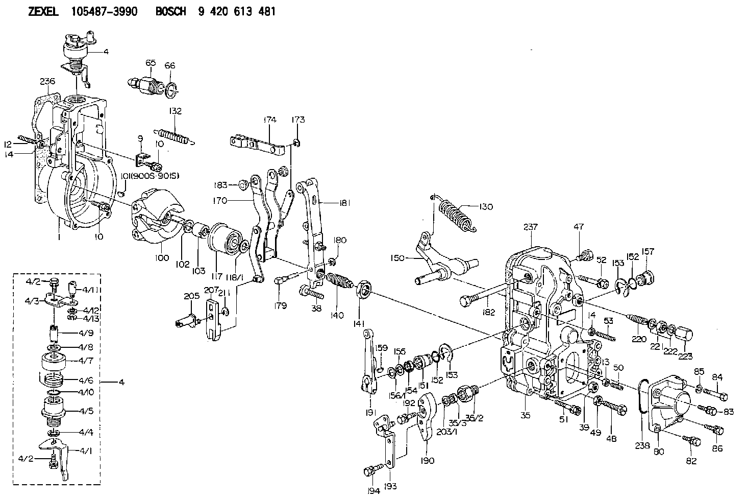
| 1. | [1] | 154000-9100 | GOVERNOR HOUSING |
| 4. | [1] | 154304-8221 | CONTROL LEVER |
| 4. | [1] | 154304-8221 | CONTROL LEVER |
| 4/1. | [1] | 154304-6200 | CONTROL LEVER |
| 4/2. | [2] | 154352-2000 | BLEEDER SCREW |
| 4/2. | [2] | 154352-2000 | BLEEDER SCREW |
| 4/3. | [1] | 154304-3300 | CONTROL LEVER |
| 4/4. | [1] | 029311-0230 | SHIM D18&10.3T0.5 |
| 4/5. | [1] | 154321-1500 | BUSHING |
| 4/6. | [1] | 154327-4100 | COILED SPRING |
| 4/7. | [1] | 154322-0100 | CAP |
| 4/8. | [1] | 029311-0220 | SHIM D18&10.3T0.2 |
| 4/9. | [1] | 154324-2700 | LEVER SHAFT |
| 4/10. | [1] | 029631-0030 | O-RING &9.8W2.3 |
| 4/11. | [1] | 154353-3701 | BEARING PIN |
| 4/12. | [1] | 014010-6140 | PLAIN WASHER D13&6.5T1 |
| 4/12B. | [0] | 029310-6040 | SHIM |
| 4/13. | [1] | 016010-0540 | LOCKING WASHER |
| 9. | [1] | 154350-6000 | PLATE |
| 10. | [8] | 020106-2040 | BLEEDER SCREW M6P1L20 |
| 10. | [8] | 020106-2040 | BLEEDER SCREW M6P1L20 |
| 12. | [1] | 154010-1100 | FLAT-HEAD SCREW |
| 13. | [1] | 029240-6010 | UNION NUT M6P1.0H5* |
| 14. | [2] | 154011-0100 | HEXAGON NUT |
| 14. | [2] | 154011-0100 | HEXAGON NUT |
| 35. | [1] | 154514-9920 | GOVERNOR COVER |
| 35/2. | [1] | 154321-1800 | BUSHING |
| 35/3. | [1] | 029621-0080 | PACKING RING |
| 38. | [1] | 154031-3500 | FLAT-HEAD SCREW |
| 39. | [1] | 154011-1600 | UNION NUT |
| 47. | [1] | 154036-0300 | CAPSULE |
| 48. | [1] | 154010-5500 | BLEEDER SCREW M10P1.25L42 |
| 49. | [1] | 154011-2100 | UNION NUT |
| 50. | [1] | 155615-1100 | FLAT-HEAD SCREW M6P1.0L37 |
| 51. | [4] | 020106-3840 | BLEEDER SCREW |
| 52. | [2] | 020106-5040 | BLEEDER SCREW |
| 53. | [1] | 154010-1100 | FLAT-HEAD SCREW |
| 65. | [1] | 153021-2220 | STOPPING DEVICE |
| 66. | [1] | 026524-3040 | GASKET |
| 80. | [1] | 154060-7300 | COVER |
| 82. | [1] | 029020-6210 | BLEEDER SCREW |
| 83. | [1] | 029020-6210 | BLEEDER SCREW |
| 84. | [1] | 010006-3840 | BLEEDER SCREW |
| 85. | [1] | 014110-6440 | LOCKING WASHER |
| 86. | [1] | 029020-6210 | BLEEDER SCREW |
| 100. | [1] | 154100-9520 | FLYWEIGHT ASSEMBLY |
| 101. | [1] | 025803-1310 | WOODRUFF KEY |
| 102. | [1] | 029321-2020 | LOCKING WASHER |
| 103. | [1] | 029231-2030 | UNION NUT |
| 117. | [1] | 154123-2320 | SLIDING PIECE |
| 118/1. | [0] | 029311-0010 | SHIM D14&10.1T0.2 |
| 118/1. | [0] | 029311-0180 | SHIM D14&10.1T0.3 |
| 118/1. | [0] | 029311-0190 | SHIM D14&10.1T0.40 |
| 118/1. | [0] | 029311-0210 | SHIM D14&10.1T1 |
| 118/1. | [0] | 139410-0000 | SHIM D14.0&10.1T0.5 |
| 118/1. | [0] | 139410-0100 | SHIM D14.0&10.1T1.5 |
| 118/1. | [0] | 139410-3000 | SHIM D14&10.1T2.0 |
| 118/1. | [0] | 139410-3100 | SHIM D14&10.1T3.0 |
| 118/1. | [0] | 139410-3200 | SHIM D14&10.1T4.0 |
| 130. | [1] | 154150-6200 | GOVERNOR SPRING |
| 132. | [1] | 154154-4000 | COILED SPRING |
| 140. | [1] | 154180-0520 | HEADLESS SCREW |
| 141. | [1] | 029201-6010 | UNION NUT |
| 150. | [1] | 154200-3701 | SWIVELLING LEVER |
| 151. | [1] | 154204-2001 | BUSHING |
| 152. | [2] | 029631-8020 | O-RING |
| 152. | [2] | 029631-8020 | O-RING |
| 153. | [2] | 154354-3900 | LOCKING WASHER |
| 153. | [2] | 154354-3900 | LOCKING WASHER |
| 154. | [1] | 139611-0000 | PACKING RING |
| 155. | [1] | 139411-0000 | SHIM |
| 156/1. | [0] | 029311-1110 | SHIM D17&11T0.1 |
| 156/1. | [0] | 029311-1120 | SHIM D17&11T0.2 |
| 156/1. | [0] | 029311-1130 | SHIM D17&11T0.3 |
| 157. | [1] | 154204-3400 | BUSHING |
| 159. | [1] | 025803-1310 | WOODRUFF KEY |
| 170. | [1] | 154216-0120 | FORK LEVER |
| 173. | [1] | 016010-0540 | LOCKING WASHER |
| 174. | [1] | 154230-4920 | STRAP |
| 179. | [1] | 154238-0301 | BEARING PIN |
| 180. | [1] | 016010-0540 | LOCKING WASHER |
| 181. | [1] | 154236-5300 | TENSIONING LEVER |
| 182. | [1] | 154237-0900 | BEARING PIN |
| 183. | [2] | 154237-0600 | BUSHING |
| 190. | [1] | 154360-2700 | CONTROL LEVER |
| 191. | [1] | 154309-9620 | CONTROL LEVER |
| 192. | [1] | 020006-1670 | BLEEDER SCREW M6P1L16 7T |
| 193. | [1] | 154369-2100 | CONTROL LEVER |
| 194. | [2] | 020006-1240 | BLEEDER SCREW M6P1L12 4T |
| 203/1. | [0] | 029311-0640 | SHIM D26.0&10.2T0.95 |
| 203/1. | [0] | 029311-0650 | SHIM D26.0&10.2T0.20 |
| 203/1. | [0] | 029311-0660 | SHIM D26.0&10.2T0.25 |
| 203/1. | [0] | 029311-0670 | SHIM D26.0&10.2T0.30 |
| 203/1. | [0] | 029311-0680 | SHIM D26.0&10.2T0.35 |
| 203/1. | [0] | 029311-0690 | SHIM D26.0&10.2T0.40 |
| 203/1. | [0] | 029311-0700 | SHIM D26.0&10.2T0.50 |
| 203/1. | [0] | 139410-1400 | SHIM D26&10.2T0.7 |
| 203/1. | [0] | 139410-1500 | SHIM D26&10.2T0.9 |
| 203/1. | [0] | 139410-1600 | SHIM D26&10.2T0.8 |
| 203/1. | [0] | 139410-2700 | SHIM D26&10.2T0.6 |
| 205. | [1] | 154324-3100 | LEVER SHAFT |
| 207. | [1] | 154326-0300 | CONTROL LEVER |
| 211. | [1] | 016010-0840 | LOCKING WASHER |
| 220. | [1] | 154050-3520 | HEADLESS SCREW |
| 221. | [1] | 029201-2140 | UNION NUT |
| 222. | [2] | 026512-1540 | GASKET D15.4&12.2T1.50 |
| 223. | [1] | 154159-1200 | CAP NUT |
| 236. | [1] | 154371-5600 | GASKET |
| 237. | [1] | 154390-0300 | GASKET |
| 238. | [1] | 029635-2020 | O-RING |
| 900S. | [1] | 025803-1310 | WOODRUFF KEY |
| 901S. | [1] | 025803-1610 | WOODRUFF KEY |
Include in #1:
106671-8190
as GOVERNOR
Cross reference number
Zexel num
Bosch num
Firm num
Name
105487-3990
223202550A HINO
GOVERNOR
K 14JN MECHANICAL GOVERNOR GOV RFD GOV
K 14JN MECHANICAL GOVERNOR GOV RFD GOV
105487-3990
S223202550A HINO
GOVERNOR
A K 14JN MECHANICAL GOVERNOR GOV RFD GOV
A K 14JN MECHANICAL GOVERNOR GOV RFD GOV
Information:
start by:a) remove fuel injection pump housing and governor 1. Install the fuel injection pump housing on tool (A).2. Remove the bolts (1) that hold the governor housing (2) to the fuel injection pump housing.3. Remove the governor housing (2). 4. Remove two springs (4) and the seat (5) from the governor housing.5. Remove the seat (7) from the shaft.6. Remove the spring (6) from the shaft.7. Remove the cover (3) from the pump housing. 8. Remove the shaft (8) and the lever (9) from the pump housing. 9. Remove the thrust collar (11) from the shaft.10. Remove the cover (10) from the pump housing. 11. Loosen the two bolts (13) that hold the torque spring assembly (12) and remove it from the pump housing. 12. Remove the pin (15) from the pump housing.13. Remove the screw (14) and the nut (16) from the pump housing.14. Remove the ring that holds the lever and remove the lever (18) from the dowel (17).15. Remove the dowel (17) from the pump housing. Dowel does not need to be removed unless camshaft is to be removed.
Pull on the shield only a small amount in each location so it will not have distortion or damage. A damaged shield must be replaced.
16. Remove the shield (19) from the camshaft with tool (B). 17. Install the timing pin (C) to hold the camshaft.18. Remove the bolts (20) that hold the flyweight assembly to the camshaft. 19. Remove the flyweight assembly (21) from the camshaft.20. Remove the timing pin (C) from the pump housing.Connection Of Governor To Fuel Injection Pump Housing
1. Put the fuel injection pump housing on the bracket assembly (A).2. Install the timing pin (B) to hold the camshaft.3. Put the flyweight assembly (1) in position on the camshaft. Be sure the pin that holds the shaft (2) is in position on the back of the flyweight assembly.4. Install the bolts that hold the flyweight assembly to the camshaft and tighten to a torque of 10 2 lb. ft. (1.38 0.28 mkg).5. Remove the timing pin (B). 6. Put the shield (3) in position over the flyweights. 7. Use the driver (C) to install the shield the remainder of the way on to the camshaft. 8. Put a new O-ring seal on the dowel (4) and install the dowel in the pump housing. Make the dowel even with the machined surface of the counterbore on the outside of the housing. 9. Put the lever (8) on the dowel (4) and install the ring that holds it on the dowel.10. Install the screw (6) and the nut (7) in the pump housing.11. Install the pin (5) in the pump housing. 12. Put the torque spring assembly (10) in position on the housing and tighten the two bolts (11) that hold it to the housing.13. Install the cover (9) on the pump housing. 14. Put the thrust collar (13) in position between the flyweights. Lift the flyweights up with a piece of wire