Information governor
BOSCH
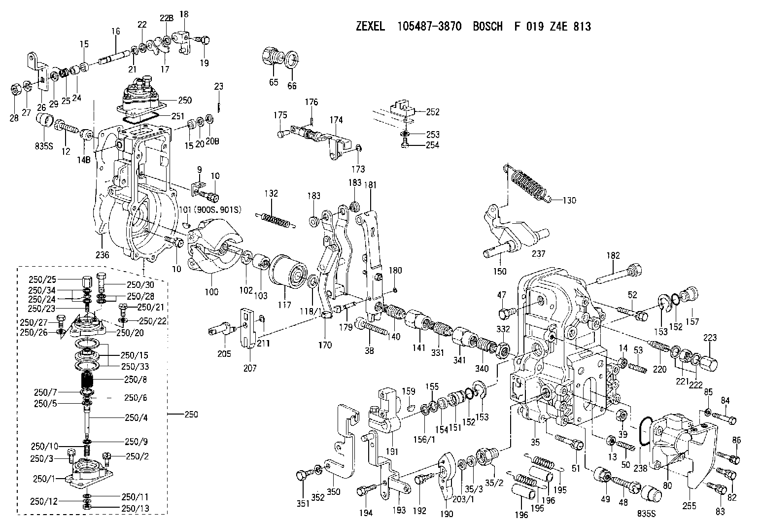
F 019 Z4E 813
f019z4e813
ZEXEL
105487-3870
1054873870
HINO
223004091A
223004091a
Rating:
Scheme ###:
| 1. | [1] | 154004-1621 | GOVERNOR HOUSING |
| 9. | [1] | 154353-5601 | PLATE |
| 10. | [8] | 020106-2040 | BLEEDER SCREW M6P1L20 |
| 10. | [8] | 020106-2040 | BLEEDER SCREW M6P1L20 |
| 12. | [1] | 154010-7300 | BLEEDER SCREW M8P1.25L60 |
| 13. | [1] | 029240-6010 | UNION NUT M6P1.0H5* |
| 14. | [1] | 154011-2300 | UNION NUT |
| 14B. | [1] | 154011-0100 | HEXAGON NUT |
| 15. | [2] | 029620-8050 | PACKING RING |
| 15. | [2] | 029620-8050 | PACKING RING |
| 16. | [1] | 155004-3200 | LEVER SHAFT |
| 17. | [1] | 154408-1520 | CONTROL LEVER |
| 18. | [1] | 155003-1920 | CONTROL LEVER |
| 19. | [1] | 155006-0700 | BLEEDER SCREW |
| 20. | [1] | 139308-0900 | PLAIN WASHER D16&8T1 |
| 20B. | [1] | 139308-1000 | PLAIN WASHER D16&8T1.5 |
| 21. | [1] | 016010-0740 | LOCKING WASHER |
| 22. | [0] | 029310-8040 | SHIM D13.5&8T0.2 |
| 22. | [7] | 139408-1400 | SHIM |
| 22B. | [0] | 029310-8050 | SHIM D13.5&8T0.5 |
| 22B. | [7] | 139408-1500 | SHIM |
| 23. | [1] | 025520-1210 | SPLIT PIN |
| 24. | [1] | 154206-2000 | BUSHING |
| 25. | [1] | 154327-4400 | COILED SPRING |
| 26. | [1] | 154367-4300 | CONTROL LEVER |
| 27. | [1] | 014110-8440 | LOCKING WASHER |
| 28. | [1] | 013020-8040 | UNION NUT M8P1.25H7 |
| 29. | [1] | 139408-1400 | SHIM |
| 29B. | [0] | 139408-1400 | SHIM |
| 29C. | [0] | 139408-1500 | SHIM |
| 35. | [1] | 154514-8820 | GOVERNOR COVER |
| 35/2. | [1] | 154321-1800 | BUSHING |
| 35/3. | [1] | 029621-0080 | PACKING RING |
| 38. | [1] | 154031-3500 | FLAT-HEAD SCREW |
| 39. | [1] | 154011-1600 | UNION NUT |
| 47. | [1] | 154036-0300 | CAPSULE |
| 48. | [1] | 154010-7100 | BLEEDER SCREW M10P1.25L47 |
| 49. | [1] | 154011-2200 | UNION NUT |
| 50. | [1] | 155615-1100 | FLAT-HEAD SCREW M6P1.0L37 |
| 51. | [4] | 020106-3840 | BLEEDER SCREW |
| 52. | [2] | 020106-5040 | BLEEDER SCREW |
| 53. | [1] | 154010-0100 | FLAT-HEAD SCREW |
| 65. | [1] | 153021-2720 | STOPPING DEVICE |
| 66. | [1] | 026524-3040 | GASKET |
| 80. | [1] | 154063-8100 | COVER |
| 82. | [1] | 029020-6210 | BLEEDER SCREW |
| 83. | [1] | 029020-6240 | BLEEDER SCREW |
| 84. | [1] | 010006-3840 | BLEEDER SCREW |
| 85. | [1] | 014110-6440 | LOCKING WASHER |
| 86. | [1] | 020006-1840 | BLEEDER SCREW M6P1L18 |
| 100. | [1] | 154100-9520 | FLYWEIGHT ASSEMBLY |
| 101. | [1] | 025803-1310 | WOODRUFF KEY |
| 102. | [1] | 029321-2020 | LOCKING WASHER |
| 103. | [1] | 029231-2030 | UNION NUT |
| 117. | [1] | 154123-2320 | SLIDING PIECE |
| 118/1. | [0] | 029311-0010 | SHIM D14&10.1T0.2 |
| 118/1. | [0] | 029311-0180 | SHIM D14&10.1T0.3 |
| 118/1. | [0] | 029311-0190 | SHIM D14&10.1T0.40 |
| 118/1. | [0] | 029311-0210 | SHIM D14&10.1T1 |
| 118/1. | [0] | 139410-0000 | SHIM D14.0&10.1T0.5 |
| 118/1. | [0] | 139410-0100 | SHIM D14.0&10.1T1.5 |
| 118/1. | [0] | 139410-3000 | SHIM D14&10.1T2.0 |
| 118/1. | [0] | 139410-3100 | SHIM D14&10.1T3.0 |
| 118/1. | [0] | 139410-3200 | SHIM D14&10.1T4.0 |
| 130. | [1] | 154150-6200 | GOVERNOR SPRING |
| 132. | [1] | 154154-0701 | COILED SPRING |
| 140. | [1] | 154180-0520 | HEADLESS SCREW |
| 141. | [1] | 029201-6220 | UNION NUT |
| 150. | [1] | 154200-3701 | SWIVELLING LEVER |
| 151. | [1] | 154204-2001 | BUSHING |
| 152. | [2] | 029631-8020 | O-RING |
| 152. | [2] | 029631-8020 | O-RING |
| 153. | [2] | 154354-3900 | LOCKING WASHER |
| 153. | [2] | 154354-3900 | LOCKING WASHER |
| 154. | [1] | 139611-0000 | PACKING RING |
| 155. | [1] | 139411-0000 | SHIM |
| 156/1. | [0] | 029311-1110 | SHIM D17&11T0.1 |
| 156/1. | [0] | 029311-1120 | SHIM D17&11T0.2 |
| 156/1. | [0] | 029311-1130 | SHIM D17&11T0.3 |
| 157. | [1] | 154204-3400 | BUSHING |
| 159. | [1] | 025803-1310 | WOODRUFF KEY |
| 170. | [1] | 154211-7520 | FORK LEVER |
| 173. | [1] | 016010-0540 | LOCKING WASHER |
| 174. | [1] | 154230-9920 | STRAP |
| 175. | [1] | 159231-4900 | BEARING PIN |
| 176. | [1] | 155402-3800 | SAFETY PIN |
| 179. | [1] | 154238-0301 | BEARING PIN |
| 180. | [1] | 016010-0540 | LOCKING WASHER |
| 181. | [1] | 154236-5300 | TENSIONING LEVER |
| 182. | [1] | 154237-0900 | BEARING PIN |
| 183. | [2] | 154237-0600 | BUSHING |
| 183. | [2] | 154237-0600 | BUSHING |
| 190. | [1] | 154360-2700 | CONTROL LEVER |
| 191. | [1] | 154340-1820 | CONTROL LEVER |
| 192. | [1] | 020006-1670 | BLEEDER SCREW M6P1L16 7T |
| 193. | [1] | 154362-8320 | CONTROL LEVER |
| 194. | [2] | 020006-1240 | BLEEDER SCREW M6P1L12 4T |
| 195. | [2] | 154314-9900 | COILED SPRING |
| 195. | [2] | 154314-9900 | COILED SPRING |
| 196. | [2] | 154156-1600 | TUBE |
| 196. | [2] | 154156-1600 | TUBE |
| 203/1. | [0] | 029311-0640 | SHIM D26.0&10.2T0.95 |
| 203/1. | [0] | 029311-0650 | SHIM D26.0&10.2T0.20 |
| 203/1. | [0] | 029311-0660 | SHIM D26.0&10.2T0.25 |
| 203/1. | [0] | 029311-0670 | SHIM D26.0&10.2T0.30 |
| 203/1. | [0] | 029311-0680 | SHIM D26.0&10.2T0.35 |
| 203/1. | [0] | 029311-0690 | SHIM D26.0&10.2T0.40 |
| 203/1. | [0] | 029311-0700 | SHIM D26.0&10.2T0.50 |
| 203/1. | [0] | 139410-1400 | SHIM D26&10.2T0.7 |
| 203/1. | [0] | 139410-1500 | SHIM D26&10.2T0.9 |
| 203/1. | [0] | 139410-1600 | SHIM D26&10.2T0.8 |
| 203/1. | [0] | 139410-2700 | SHIM D26&10.2T0.6 |
| 205. | [1] | 154324-3100 | LEVER SHAFT |
| 207. | [1] | 154326-0300 | CONTROL LEVER |
| 211. | [1] | 016010-0840 | LOCKING WASHER |
| 220. | [1] | 154050-6820 | HEADLESS SCREW |
| 221. | [1] | 029201-2140 | UNION NUT |
| 222. | [2] | 026512-1540 | GASKET D15.4&12.2T1.50 |
| 223. | [1] | 154159-1200 | CAP NUT |
| 236. | [1] | 154371-5600 | GASKET |
| 237. | [1] | 154390-0300 | GASKET |
| 238. | [1] | 029635-2020 | O-RING |
| 250. | [1] | 154407-6523 | MANIFOLD-PRESSURE COMP. |
| 250. | [1] | 154407-6523 | MANIFOLD-PRESSURE COMP. |
| 250/1. | [1] | 154408-6220 | DIAPHRAGM HOUSING |
| 250/2. | [3] | 020106-1640 | BLEEDER SCREW M6P1.0L14 |
| 250/3. | [1] | 029020-6210 | BLEEDER SCREW |
| 250/4. | [1] | 154400-5101 | STOP PIN |
| 250/5. | [1] | 153400-0900 | SLOTTED WASHER |
| 250/6. | [1] | 016010-0740 | LOCKING WASHER |
| 250/7. | [0] | 029312-0180 | SHIM D25.5&20T0.5 |
| 250/7B. | [0] | 029312-0210 | SHIM D25.5&20T0.2 |
| 250/8. | [1] | 154402-4100 | COILED SPRING |
| 250/9. | [0] | 154355-3900 | SHIM D18&12.5T0.10 |
| 250/9B. | [0] | 154355-4000 | SHIM D18&12.5T0.20 |
| 250/9C. | [0] | 154355-4100 | SHIM D18&12.5T0.30 |
| 250/10. | [1] | 154402-2600 | COILED SPRING |
| 250/11. | [1] | 153400-0800 | SPRING SEAT |
| 250/12. | [1] | 014110-5440 | LOCKING WASHER |
| 250/13. | [1] | 013030-5240 | UNION NUT M5P0.8H3.2 |
| 250/15. | [1] | 154400-7720 | DIAPHRAGM |
| 250/20. | [1] | 154404-3900 | COVER |
| 250/21. | [3] | 029010-6310 | BLEEDER SCREW |
| 250/22. | [3] | 014110-6440 | LOCKING WASHER |
| 250/23. | [1] | 154404-1100 | FLAT-HEAD SCREW |
| 250/24. | [1] | 013030-6040 | UNION NUT M6P1H3.6 |
| 250/25. | [1] | 154035-1900 | CAP NUT |
| 250/26. | [1] | 026506-1040 | GASKET D9.9&6.2T1 |
| 250/27. | [1] | 029010-6010 | CAPSULE M6P1.0L7 |
| 250/28. | [2] | 026510-1340 | GASKET D13.4&10.2T1 |
| 250/30. | [1] | 029731-0180 | EYE BOLT |
| 250/33. | [2] | 154413-2600 | GASKET |
| 250/34. | [2] | 026506-1040 | GASKET D9.9&6.2T1 |
| 251. | [1] | 154390-2000 | GASKET |
| 252. | [1] | 154232-1720 | PLATE |
| 253. | [1] | 029320-5020 | LOCKING WASHER |
| 254. | [1] | 010535-1040 | FLAT-HEAD SCREW M5P0.8L10 |
| 255. | [1] | 154356-2120 | BRACKET |
| 331. | [1] | 154176-5620 | HEADLESS SCREW |
| 332. | [1] | 029201-6080 | UNION NUT |
| 340. | [1] | 154176-5720 | HEADLESS SCREW |
| 341. | [1] | 029201-6010 | UNION NUT |
| 350. | [1] | 154356-1200 | BRACKET |
| 351. | [2] | 010010-1240 | BLEEDER SCREW M10P1.5L12 4T |
| 352. | [2] | 014111-0440 | LOCKING WASHER |
| 835S. | [2] | 154062-1700 | CAP D20L32 |
| 835S. | [2] | 154062-1700 | CAP D20L32 |
| 900S. | [1] | 025803-1310 | WOODRUFF KEY |
| 901S. | [1] | 025803-1610 | WOODRUFF KEY |
Include in #1:
106671-8022
as GOVERNOR
Cross reference number
Zexel num
Bosch num
Firm num
Name
105487-3870
223004091A HINO
GOVERNOR
K 14JN MECHANICAL GOVERNOR GOV RFD GOV
K 14JN MECHANICAL GOVERNOR GOV RFD GOV
105487-3870
223004800A HINO
GOVERNOR
A K 14JN MECHANICAL GOVERNOR GOV RFD GOV
A K 14JN MECHANICAL GOVERNOR GOV RFD GOV
Information:
Start By:a. remove valve cover 1. Remove the cover from the flywheel housing and install Tool (A). Turn the crankshaft with Tool (A) until there is no pressure on rocker arm (2).2. Use Tool (B) as shown to move the rocker arm away from push rod (1). Remove push rod (1). 3. Install Tool (C) on the valve lifter. Remove valve lifter (3) from the block. 4. Remove spring guide (4) from the valve lifter.5. Do Steps 1 through 4 again for the other valve lifters and push rods if necessary.Install Valve Lifters & Push Rods
Any time the valve lifter is removed from the machine, a new spring guide must be installed on the valve lifter.1. Install spring guide (1) on valve lifter (2). 2. Put the valve lifter in position on Tool (A) as shown. Make sure spring guide (1) is in position in the groove (slot) in the valve lifter as shown. 3. Use a soft hammer to install Tool (B) over spring guide (1). Make sure the groove in Tool (B) is in alignment with spring guide (1). 4. Put clean engine oil on valve lifter (2). Use Tool (B) to install the valve lifter in the engine block. Make sure the end of the spring guide is in alignment with the small hole in the block.5. When the valve lifter is in position in the block, use Tool (C) to push the valve lifter off of Tool (C). 6. Use Tool (E) to turn the crankshaft to make sure there is not pressure on the push rods and rocker arms.7. Put push rod (3) in position in the block. Use Tool (D) to move rocker arm (4) away from the push rod far enough to put push rod (3) in position under the rocker arm.End By:a. install valve cover
Any time the valve lifter is removed from the machine, a new spring guide must be installed on the valve lifter.1. Install spring guide (1) on valve lifter (2). 2. Put the valve lifter in position on Tool (A) as shown. Make sure spring guide (1) is in position in the groove (slot) in the valve lifter as shown. 3. Use a soft hammer to install Tool (B) over spring guide (1). Make sure the groove in Tool (B) is in alignment with spring guide (1). 4. Put clean engine oil on valve lifter (2). Use Tool (B) to install the valve lifter in the engine block. Make sure the end of the spring guide is in alignment with the small hole in the block.5. When the valve lifter is in position in the block, use Tool (C) to push the valve lifter off of Tool (C). 6. Use Tool (E) to turn the crankshaft to make sure there is not pressure on the push rods and rocker arms.7. Put push rod (3) in position in the block. Use Tool (D) to move rocker arm (4) away from the push rod far enough to put push rod (3) in position under the rocker arm.End By:a. install valve cover