Information governor
BOSCH
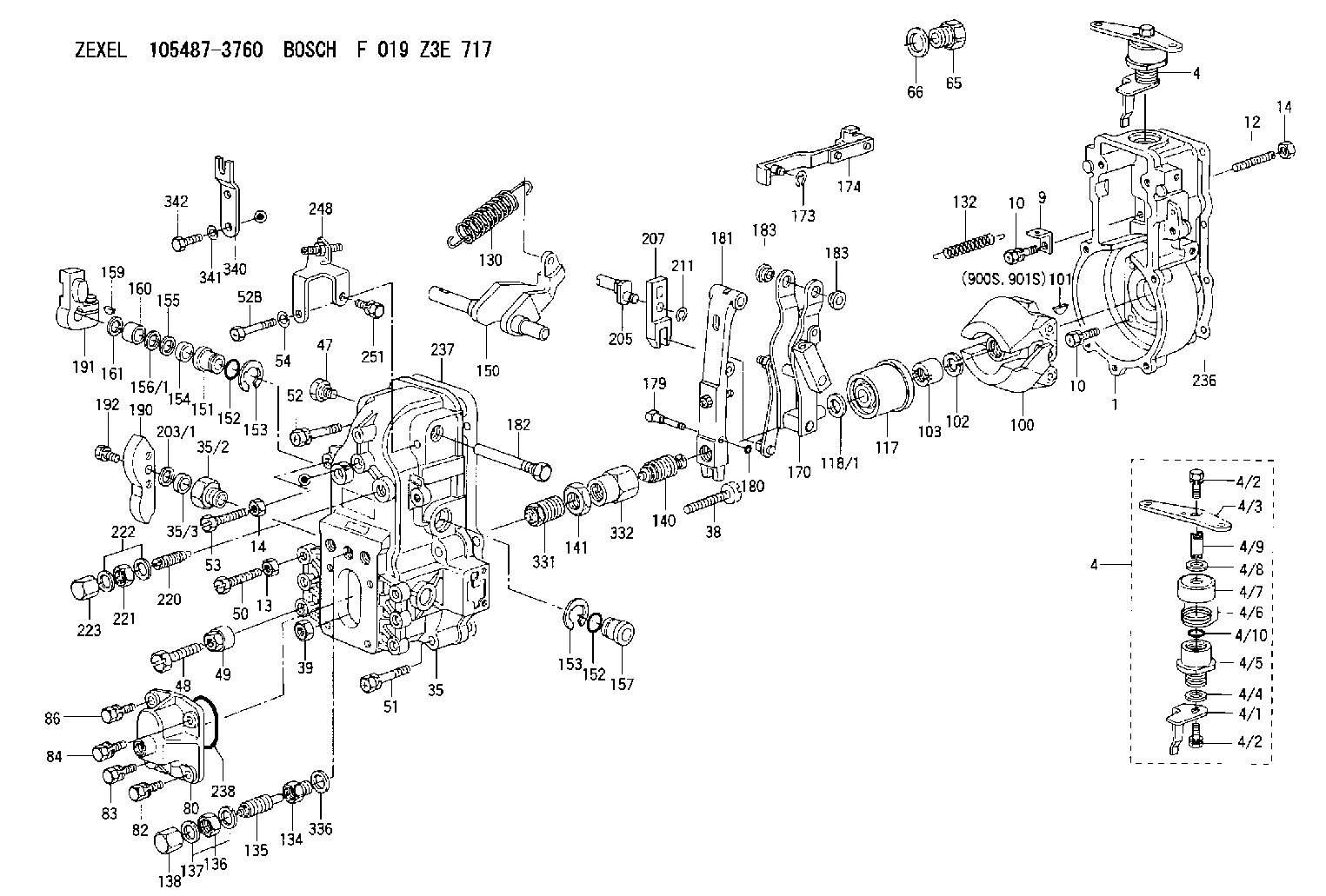
F 019 Z3E 717
f019z3e717
ZEXEL
105487-3760
1054873760
NISSAN-DIESEL
1910197568
1910197568
Rating:
Scheme ###:
| 1. | [1] | 154000-4700 | GOVERNOR HOUSING |
| 4. | [1] | 154366-5720 | CONTROL LEVER |
| 4. | [1] | 154366-5720 | CONTROL LEVER |
| 4/1. | [1] | 154304-6200 | CONTROL LEVER |
| 4/2. | [2] | 154352-2000 | BLEEDER SCREW |
| 4/2. | [2] | 154352-2000 | BLEEDER SCREW |
| 4/3. | [1] | 154366-5700 | CONTROL LEVER |
| 4/4. | [1] | 029311-0230 | SHIM D18&10.3T0.5 |
| 4/5. | [1] | 154321-1500 | BUSHING |
| 4/6. | [1] | 154327-2901 | COILED SPRING |
| 4/7. | [1] | 154322-0100 | CAP |
| 4/8. | [1] | 029311-0220 | SHIM D18&10.3T0.2 |
| 4/9. | [1] | 154324-2700 | LEVER SHAFT |
| 4/10. | [1] | 029631-0030 | O-RING &9.8W2.3 |
| 9. | [1] | 154350-6000 | PLATE |
| 10. | [8] | 020106-2040 | BLEEDER SCREW M6P1L20 |
| 10. | [8] | 020106-2040 | BLEEDER SCREW M6P1L20 |
| 12. | [1] | 154010-0100 | FLAT-HEAD SCREW |
| 13. | [1] | 029240-6010 | UNION NUT M6P1.0H5* |
| 14. | [2] | 154011-0100 | HEXAGON NUT |
| 14. | [2] | 154011-0100 | HEXAGON NUT |
| 35. | [1] | 154514-9420 | GOVERNOR COVER |
| 35/2. | [1] | 154321-2300 | BUSHING |
| 35/3. | [1] | 029621-0080 | PACKING RING |
| 38. | [1] | 154031-3500 | FLAT-HEAD SCREW |
| 39. | [1] | 154011-1600 | UNION NUT |
| 47. | [1] | 154036-1200 | CAPSULE |
| 48. | [1] | 154010-5500 | BLEEDER SCREW M10P1.25L42 |
| 49. | [1] | 154011-2100 | UNION NUT |
| 50. | [1] | 155615-1600 | BLEEDER SCREW |
| 51. | [4] | 020106-3840 | BLEEDER SCREW |
| 52. | [1] | 020106-5040 | BLEEDER SCREW |
| 52B. | [1] | 029010-6850 | BLEEDER SCREW |
| 53. | [1] | 154010-2900 | BLEEDER SCREW |
| 54. | [1] | 014110-6440 | LOCKING WASHER |
| 65. | [1] | 155404-1700 | CAP |
| 66. | [1] | 026524-3040 | GASKET |
| 80. | [1] | 154063-4701 | COVER |
| 82. | [1] | 029020-6210 | BLEEDER SCREW |
| 83. | [1] | 020006-1640 | BLEEDER SCREW M6P1L16 4T |
| 84. | [1] | 029020-6210 | BLEEDER SCREW |
| 86. | [1] | 020006-1640 | BLEEDER SCREW M6P1L16 4T |
| 100. | [1] | 154100-9520 | FLYWEIGHT ASSEMBLY |
| 101. | [1] | 025803-1310 | WOODRUFF KEY |
| 102. | [1] | 029321-2020 | LOCKING WASHER |
| 103. | [1] | 029231-2030 | UNION NUT |
| 117. | [1] | 154123-2320 | SLIDING PIECE |
| 118/1. | [0] | 029311-0010 | SHIM D14&10.1T0.2 |
| 118/1. | [0] | 029311-0180 | SHIM D14&10.1T0.3 |
| 118/1. | [0] | 029311-0190 | SHIM D14&10.1T0.40 |
| 118/1. | [0] | 029311-0210 | SHIM D14&10.1T1 |
| 118/1. | [0] | 139410-0000 | SHIM D14.0&10.1T0.5 |
| 118/1. | [0] | 139410-0100 | SHIM D14.0&10.1T1.5 |
| 118/1. | [0] | 139410-3000 | SHIM D14&10.1T2.0 |
| 118/1. | [0] | 139410-3100 | SHIM D14&10.1T3.0 |
| 118/1. | [0] | 139410-3200 | SHIM D14&10.1T4.0 |
| 130. | [1] | 154150-6200 | GOVERNOR SPRING |
| 132. | [1] | 154154-4000 | COILED SPRING |
| 134. | [1] | 154370-3000 | ADAPTOR |
| 135. | [1] | 154158-0920 | HEADLESS SCREW |
| 136. | [1] | 029201-2130 | UNION NUT M12P1.0H6 |
| 137. | [2] | 026512-1540 | GASKET D15.4&12.2T1.50 |
| 138. | [1] | 154159-1200 | CAP NUT |
| 140. | [1] | 154180-5020 | HEADLESS SCREW |
| 141. | [1] | 029201-6010 | UNION NUT |
| 150. | [1] | 154200-3701 | SWIVELLING LEVER |
| 151. | [1] | 154204-2001 | BUSHING |
| 152. | [2] | 029631-8020 | O-RING |
| 152. | [2] | 029631-8020 | O-RING |
| 153. | [2] | 154354-3900 | LOCKING WASHER |
| 153. | [2] | 154354-3900 | LOCKING WASHER |
| 154. | [1] | 139611-0000 | PACKING RING |
| 155. | [1] | 139411-0000 | SHIM |
| 156/1. | [0] | 029311-1110 | SHIM D17&11T0.1 |
| 156/1. | [0] | 029311-1120 | SHIM D17&11T0.2 |
| 156/1. | [0] | 029311-1130 | SHIM D17&11T0.3 |
| 157. | [1] | 154204-3400 | BUSHING |
| 159. | [1] | 025803-1310 | WOODRUFF KEY |
| 160. | [1] | 154206-0900 | BUSHING |
| 161. | [0] | 154206-0200 | PLAIN WASHER D19.5&11.2T1.0 |
| 170. | [1] | 154211-7220 | FORK LEVER |
| 173. | [1] | 016010-0540 | LOCKING WASHER |
| 174. | [1] | 154230-4920 | STRAP |
| 179. | [1] | 154238-0301 | BEARING PIN |
| 180. | [1] | 016010-0540 | LOCKING WASHER |
| 181. | [1] | 154236-5300 | TENSIONING LEVER |
| 182. | [1] | 154237-0900 | BEARING PIN |
| 183. | [2] | 154237-0600 | BUSHING |
| 183. | [2] | 154237-0600 | BUSHING |
| 190. | [1] | 154368-4020 | CONTROL LEVER |
| 191. | [1] | 154340-0020 | CONTROL LEVER |
| 192. | [1] | 020006-1670 | BLEEDER SCREW M6P1L16 7T |
| 203/1. | [0] | 139410-0200 | SHIM D32&10.2T0.1 |
| 203/1. | [0] | 139410-0300 | SHIM D32&10.2T0.3 |
| 203/1. | [0] | 139410-0400 | SHIM D32&10.2T0.5 |
| 203/1. | [0] | 139410-0500 | SHIM D32&10.2T0.9 |
| 205. | [1] | 154324-3100 | LEVER SHAFT |
| 207. | [1] | 154326-0300 | CONTROL LEVER |
| 211. | [1] | 016010-0840 | LOCKING WASHER |
| 220. | [1] | 154050-6220 | HEADLESS SCREW |
| 221. | [1] | 029201-2130 | UNION NUT M12P1.0H6 |
| 222. | [2] | 026512-1540 | GASKET D15.4&12.2T1.50 |
| 223. | [1] | 154159-1200 | CAP NUT |
| 236. | [1] | 154371-5600 | GASKET |
| 237. | [1] | 154390-0300 | GASKET |
| 238. | [1] | 029635-2020 | O-RING |
| 248. | [1] | 154359-6520 | BRACKET |
| 251. | [1] | 020106-1240 | BLEEDER SCREW M6P1.0L12 |
| 331. | [1] | 154179-4720 | HEADLESS SCREW |
| 332. | [1] | 029201-6220 | UNION NUT |
| 336. | [1] | 029331-6030 | GASKET |
| 340. | [1] | 154370-4700 | PLATE |
| 341. | [2] | 014110-8440 | LOCKING WASHER |
| 342. | [2] | 010008-1440 | BLEEDER SCREW |
| 900S. | [1] | 025803-1310 | WOODRUFF KEY |
| 901S. | [1] | 025803-1610 | WOODRUFF KEY |
Cross reference number
Zexel num
Bosch num
Firm num
Name
105487-3760
1910197568 NISSAN-DIESEL
GOVERNOR
K 14JN MECHANICAL GOVERNOR GOV RFD GOV
K 14JN MECHANICAL GOVERNOR GOV RFD GOV
Information:
1. Remove the bolts (2) that hold suction bell and tubes (1) to the engine block. 2. Remove O-ring seals (3) from the tubes. Inspect O-ring seals for damage. Make a replacement if necessary. 3. Remove clip (5) and then remove screen (4). Clean the screen if necessary. 4. Remove the bolts (7) that hold the oil pump to the engine block. Remove oil pump (6).Install Oil Pump
1. Put the oil pump (1) in position on the engine block and install the bolts that hold it. 2. Install screen (2) with the clip (3) that holds it. 3. Put a small amount of clean oil on O-ring seals (4). Install the O-ring seals on the tubes. 4. Put tubes (5) in position in the oil pump.5. Put suction bell (6) and support in position on the engine block and install the four bolts that hold it.End By:a. install oil panDisassemble Oil Pump
Start By:a. remove oil pump 1. Remove bolts (1) and cover (2). Remove spacer from cover, then remove spring and plunger from pump bore. 2. Remove bolt (4), washer (3) and gear (5) from the pump. 3. Remove bolts (7) then remove shaft assembly (6) from the pump. 4. Remove bolts (8) then remove cover assembly (9) from the pump body. 5. Use Tooling (A) to remove bearings (10) from cover assembly (9). 6. Remove shaft and gear assembly (11) from the pump body. 7. Remove bolt and washer from gear (12). Use Tool (B) to remove gear (12) 8. Remove shaft and gear assembly (13) from the pump body. 9. Use Tooling (A) to remove bearings from pump body bore.Assemble Oil Pump
1. Use Tooling (A) to install bearings (2) until they are even with the outside surface of main pump body (1). Install bearings (2) so the junctions in the bearings are 30 15 degrees from the center line of the bearing bores and toward the oil pump outlet passage as shown. 2. Install shaft and gear assembly (3) in the pump body. Install key in shaft. 3. Install gear (4) on the shaft. Install bolt and washer on the shaft. 4. Install shaft and gear assembly (5) in the pump body. 5. Install bearings (7) in the cover assembly (6) with Tooling (A). Install the bearings until they are in position the same distance in from each side of the cover assembly. Install the bearings with the oil holes in the bearings in alignment with the oil holes in the cover assembly and the junctions in the bearings in alignment with the cavity in the cover assembly. 6. Install cover assembly (6) on the pump body. 7. Install shaft assembly (8) on the oil pump body with the two bolts that hold it. 8. Install gear (9) on shaft assembly. Install washer and bolt on gear (9). 9. Install plunger (10), spring (13) and spacer (11) in the pump body. Install cover (12) and the bolts (14) that hold it.End By:a. install oil pump