Information governor
BOSCH
F 019 Z2F 084
f019z2f084
ZEXEL
105487-3690
1054873690
NISSAN-DIESEL
1910196864
1910196864
Rating:
Scheme ###:
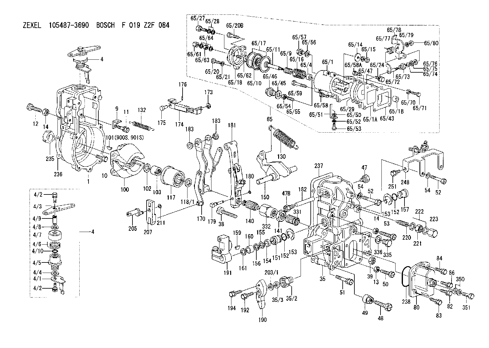
| 1. | [1] | 154004-0100 | GOVERNOR HOUSING |
| 4. | [1] | 154304-0920 | CONTROL LEVER |
| 4. | [1] | 154304-0920 | CONTROL LEVER |
| 4/1. | [1] | 154304-0100 | CONTROL LEVER |
| 4/2. | [2] | 154352-2000 | BLEEDER SCREW |
| 4/2. | [2] | 154352-2000 | BLEEDER SCREW |
| 4/3. | [1] | 154304-0900 | CONTROL LEVER |
| 4/4. | [1] | 029311-0230 | SHIM D18&10.3T0.5 |
| 4/5. | [1] | 154321-1500 | BUSHING |
| 4/6. | [1] | 154327-2901 | COILED SPRING |
| 4/7. | [1] | 154322-0100 | CAP |
| 4/8. | [1] | 029311-0220 | SHIM D18&10.3T0.2 |
| 4/9. | [1] | 154324-2700 | LEVER SHAFT |
| 4/10. | [1] | 029631-0030 | O-RING &9.8W2.3 |
| 9. | [1] | 154350-6000 | PLATE |
| 10. | [4] | 020106-2040 | BLEEDER SCREW M6P1L20 |
| 11. | [4] | 020106-1840 | BLEEDER SCREW M6P1L18 |
| 12. | [1] | 154010-2200 | BLEEDER SCREW |
| 13. | [1] | 029240-6010 | UNION NUT M6P1.0H5* |
| 14. | [2] | 154011-0100 | HEXAGON NUT |
| 14. | [2] | 154011-0100 | HEXAGON NUT |
| 35. | [1] | 154513-8920 | GOVERNOR COVER |
| 35/2. | [1] | 154321-2000 | BUSHING |
| 35/3. | [1] | 029621-0080 | PACKING RING |
| 38. | [1] | 154031-3401 | FLAT-HEAD SCREW |
| 39. | [1] | 029201-0160 | UNION NUT |
| 47. | [1] | 154036-1800 | CAPSULE |
| 47B. | [1] | 154036-1900 | CAPSULE |
| 48. | [1] | 154010-5500 | BLEEDER SCREW M10P1.25L42 |
| 49. | [1] | 154011-2100 | UNION NUT |
| 50. | [1] | 155615-1900 | BLEEDER SCREW |
| 51. | [5] | 020106-4540 | BLEEDER SCREW M6P1.0L45 |
| 52. | [2] | 010006-6040 | BLEEDER SCREW |
| 52. | [2] | 010006-6040 | BLEEDER SCREW |
| 53. | [1] | 154010-8700 | BLEEDER SCREW |
| 54. | [2] | 014110-6440 | LOCKING WASHER |
| 54. | [2] | 014110-6440 | LOCKING WASHER |
| 65. | [1] | 154417-8321 | MANIFOLD-PRESSURE COMP. |
| 65/1. | [1] | 154412-9520 | GOVERNOR HOUSING |
| 65/1A. | [1] | 154412-0201 | SPACER BUSHING |
| 65/1B. | [1] | 134009-0000 | SPACER BUSHING |
| 65/4. | [1] | 154413-0500 | BUSHING |
| 65/9. | [1] | 154402-3900 | COILED SPRING |
| 65/10. | [1] | 154400-8220 | DIAPHRAGM |
| 65/11. | [1] | 154412-4101 | STOP PIN |
| 65/14. | [1] | 154406-5500 | SLOTTED WASHER |
| 65/15. | [1] | 013020-6040 | UNION NUT M6P1H5 |
| 65/16. | [1] | 154402-4200 | COILED SPRING |
| 65/17. | [2] | 154413-2600 | GASKET |
| 65/18. | [1] | 154404-5000 | COVER |
| 65/20. | [2] | 029010-6310 | BLEEDER SCREW |
| 65/20B. | [1] | 020106-4540 | BLEEDER SCREW M6P1.0L45 |
| 65/21. | [2] | 014110-6440 | LOCKING WASHER |
| 65/24. | [2] | 020106-2040 | BLEEDER SCREW M6P1L20 |
| 65/27. | [1] | 029731-0180 | EYE BOLT |
| 65/28. | [2] | 026510-1340 | GASKET D13.4&10.2T1 |
| 65/29. | [1] | 154390-2200 | GASKET |
| 65/43. | [1] | 154390-2300 | GASKET |
| 65/45. | [1] | 029331-8040 | GASKET |
| 65/46. | [1] | 154406-5800 | FLAT-HEAD SCREW |
| 65/47. | [1] | 014110-6440 | LOCKING WASHER |
| 65/50. | [1] | 154406-6800 | PLAIN WASHER |
| 65/51. | [1] | 154412-9800 | CONTROL LEVER |
| 65/52. | [1] | 014110-4440 | LOCKING WASHER |
| 65/53. | [1] | 010234-0820 | HEX-SOCKET-HEAD CAP SCREW |
| 65/54. | [1] | 013030-6040 | UNION NUT M6P1H3.6 |
| 65/55. | [1] | 154404-1500 | FLAT-HEAD SCREW L22.00 |
| 65/55B. | [1] | 154404-1600 | FLAT-HEAD SCREW L26.00 |
| 65/56. | [1] | 029331-2130 | GASKET |
| 65/57. | [1] | 154406-6500 | FLAT-HEAD SCREW |
| 65/58. | [2] | 020106-2840 | BLEEDER SCREW |
| 65/58A. | [1] | 020106-1440 | BLEEDER SCREW M6P1.0L14 |
| 65/59. | [1] | 139006-9300 | BLEEDER SCREW |
| 65/61. | [1] | 154035-1600 | CAP NUT |
| 65/62. | [1] | 154404-4400 | FLAT-HEAD SCREW |
| 65/63. | [1] | 013030-6040 | UNION NUT M6P1H3.6 |
| 65/64. | [2] | 026506-1040 | GASKET D9.9&6.2T1 |
| 65/70. | [1] | 029240-6010 | UNION NUT M6P1.0H5* |
| 65/71. | [1] | 029000-6290 | BLEEDER SCREW M6P1.0L19 |
| 65/72. | [1] | 154413-0021 | LEVER SHAFT |
| 65/73. | [1] | 154413-0100 | BUSHING |
| 65/74. | [1] | 139608-0000 | PACKING RING |
| 65/75. | [1] | 154413-0200 | PLAIN WASHER |
| 65/76. | [0] | 029310-8030 | SHIM D13.5&8T0.1 |
| 65/76B. | [0] | 029310-8040 | SHIM D13.5&8T0.2 |
| 65/77. | [1] | 154413-0301 | COILED SPRING |
| 65/78. | [1] | 154413-0400 | CONTROL LEVER |
| 65/79. | [1] | 014110-8440 | LOCKING WASHER |
| 65/80. | [1] | 013020-8140 | UNION NUT M8P1.25H6.5 |
| 66. | [1] | 026524-3040 | GASKET |
| 80. | [1] | 154063-8620 | COVER |
| 82. | [1] | 020006-1640 | BLEEDER SCREW M6P1L16 4T |
| 83. | [1] | 029020-6210 | BLEEDER SCREW |
| 84. | [1] | 020006-1640 | BLEEDER SCREW M6P1L16 4T |
| 86. | [1] | 029020-6210 | BLEEDER SCREW |
| 100. | [1] | 154100-9220 | FLYWEIGHT ASSEMBLY |
| 101. | [1] | 025803-1310 | WOODRUFF KEY |
| 102. | [1] | 029321-2020 | LOCKING WASHER |
| 103. | [1] | 139212-0000 | UNION NUT |
| 117. | [1] | 154123-2320 | SLIDING PIECE |
| 118/1. | [0] | 029311-0010 | SHIM D14&10.1T0.2 |
| 118/1. | [0] | 029311-0180 | SHIM D14&10.1T0.3 |
| 118/1. | [0] | 029311-0190 | SHIM D14&10.1T0.40 |
| 118/1. | [0] | 029311-0210 | SHIM D14&10.1T1 |
| 118/1. | [0] | 139410-0000 | SHIM D14.0&10.1T0.5 |
| 118/1. | [0] | 139410-0100 | SHIM D14.0&10.1T1.5 |
| 118/1. | [0] | 139410-3000 | SHIM D14&10.1T2.0 |
| 118/1. | [0] | 139410-3100 | SHIM D14&10.1T3.0 |
| 118/1. | [0] | 139410-3200 | SHIM D14&10.1T4.0 |
| 130. | [1] | 154150-9400 | GOVERNOR SPRING |
| 132. | [1] | 154154-0701 | COILED SPRING |
| 140. | [1] | 154183-2420 | HEADLESS SCREW |
| 141. | [1] | 139218-0100 | UNION NUT |
| 150. | [1] | 154200-5601 | SWIVELLING LEVER |
| 151. | [1] | 154200-5501 | BUSHING |
| 152. | [2] | 139700-0000 | O-RING |
| 152. | [2] | 139700-0000 | O-RING |
| 153. | [2] | 154354-3900 | LOCKING WASHER |
| 153. | [2] | 154354-3900 | LOCKING WASHER |
| 154. | [1] | 139610-0101 | PACKING RING |
| 155. | [1] | 139411-0100 | SHIM D22.0&12.0T0.40 |
| 156. | [0] | 139411-0200 | SHIM D18.0&12.0T0.10 |
| 156B. | [0] | 139411-0300 | SHIM D18.0&12.0T0.20 |
| 156C. | [0] | 139411-0400 | SHIM D18.0&12.0T0.30 |
| 157. | [1] | 154204-3500 | BUSHING |
| 159. | [1] | 025803-1310 | WOODRUFF KEY |
| 160. | [1] | 154206-2300 | BUSHING |
| 161. | [0] | 154206-2400 | PLAIN WASHER D20.5&12.2T1 |
| 170. | [1] | 154216-1820 | FORK LEVER |
| 173. | [1] | 016010-0540 | LOCKING WASHER |
| 174. | [1] | 154234-5320 | STRAP |
| 175. | [1] | 154222-4900 | BEARING PIN |
| 176. | [1] | 155402-3800 | SAFETY PIN |
| 179. | [1] | 154238-0201 | BEARING PIN |
| 180. | [1] | 016010-0540 | LOCKING WASHER |
| 181. | [1] | 154236-5200 | TENSIONING LEVER |
| 182. | [1] | 154237-1200 | BEARING PIN |
| 183. | [2] | 154237-1300 | BUSHING |
| 183. | [2] | 154237-1300 | BUSHING |
| 190. | [1] | 154360-2700 | CONTROL LEVER |
| 191. | [1] | 154340-5120 | CONTROL LEVER |
| 192. | [1] | 020006-1670 | BLEEDER SCREW M6P1L16 7T |
| 194. | [2] | 020006-4040 | BLEEDER SCREW |
| 203/1. | [0] | 029311-0640 | SHIM D26.0&10.2T0.95 |
| 203/1. | [0] | 029311-0650 | SHIM D26.0&10.2T0.20 |
| 203/1. | [0] | 029311-0660 | SHIM D26.0&10.2T0.25 |
| 203/1. | [0] | 029311-0670 | SHIM D26.0&10.2T0.30 |
| 203/1. | [0] | 029311-0680 | SHIM D26.0&10.2T0.35 |
| 203/1. | [0] | 029311-0690 | SHIM D26.0&10.2T0.40 |
| 203/1. | [0] | 029311-0700 | SHIM D26.0&10.2T0.50 |
| 203/1. | [0] | 139410-1400 | SHIM D26&10.2T0.7 |
| 203/1. | [0] | 139410-1500 | SHIM D26&10.2T0.9 |
| 203/1. | [0] | 139410-1600 | SHIM D26&10.2T0.8 |
| 203/1. | [0] | 139410-2700 | SHIM D26&10.2T0.6 |
| 205. | [1] | 154324-3400 | LEVER SHAFT |
| 207. | [1] | 154326-0300 | CONTROL LEVER |
| 211. | [1] | 016010-0840 | LOCKING WASHER |
| 220. | [1] | 154050-1220 | HEADLESS SCREW |
| 221. | [1] | 029201-2140 | UNION NUT |
| 222. | [2] | 026512-1540 | GASKET D15.4&12.2T1.50 |
| 223. | [1] | 154159-1200 | CAP NUT |
| 235. | [1] | 155412-5200 | IMPELLER WHEEL |
| 236. | [1] | 154371-5600 | GASKET |
| 237. | [1] | 154390-0200 | GASKET |
| 238. | [1] | 139700-0100 | O-RING |
| 248. | [1] | 154359-4320 | BRACKET |
| 251. | [1] | 020106-1240 | BLEEDER SCREW M6P1.0L12 |
| 331. | [1] | 154179-4920 | HEADLESS SCREW |
| 332. | [1] | 139218-0200 | UNION NUT |
| 335. | [1] | 154352-2600 | CAPSULE |
| 336. | [1] | 029331-6030 | GASKET |
| 350. | [2] | 029331-2120 | GASKET |
| 351. | [1] | 029731-2040 | EYE BOLT |
| 900S. | [1] | 025803-1310 | WOODRUFF KEY |
| 901S. | [1] | 025803-1610 | WOODRUFF KEY |
Cross reference number
Zexel num
Bosch num
Firm num
Name
105487-3690
F 019 Z2F 084
1910196864 NISSAN-DIESEL
GOVERNOR
* K
* K
Information:
Start By:a. remove valve covers1. Turn the flywheel with Tool (C) until there is clearance between the rocker arms and valve bridges. 2. Engage Tool (A) with the rocker arm, and move Tool (A) against the valve spring force until push rod (1) can be removed.3. Remove the other push rod for the same cylinder. Mark each push rod so it can be installed in its original position. 4. Use Tool (B) to remove valve lifter (2).5. Remove the other valve lifter for the same cylinder. Mark each valve lifter so it can be installed in its original position. 6. Remove spring (3) from lifter (2).7. Inspect spring (3). See Guideline For Reusable Parts, SEBF8066. 8. Identify the location of each valve bridge (4), then remove them.Install Push Rods, Valve Lifters & Valve Bridges
1. Put clean engine oil on each bridge dowel and the bore of each bridge. Install bridges (1) in their original position.2. Use the following procedure to adjust the valve bridges.a. Put clean SAE 30 Engine Oil in the lubrication passage of the bridge.b. Press straight down on the top contact surface of the bridge with a force of 4.45 to 44.50 N (1 to 10 lb).c. Turn the adjusting screw clockwise until the oil film in the lubrication passage of the bridge moves inward.d. Turn the adjusting screw an additional 20 to 30 degrees (1/3 to 1/2 of a flat on the hex nut).e. Hold the adjusting screw in position, and tighten the locknut to a torque of 26 to 34 N m (19 to 25 lb ft).f. Do this procedure for both bridges. Put clean engine oil on the top contact surface of both bridges. 3. Install spring (3) on valve lifter (2). 4. Fasten Tool (A) to valve lifter (2).5. Immerse valve lifter (2) in clean engine oil; then install it in its original position.6. Install the other valve lifter for the same cylinder. 7. Engage Tool (B) with the rocker arm, and move Tool (B) against the valve spring force until push rods (4) can be installed in their original position.8. Use Tool (C) to turn the flywheel so the remaining push rods can be installed. Be sure there is clearance at the rocker arms and valve bridges before compressing the valve pump.9. Check the valve clearance settings. The clearance for the intake valves is 0.38 mm (.015 in). The clearance for the exhaust valve is 0.76 mm (.030 in). See the topic "Valve Clearance Setting" in Testing & Adjusting.End By:a. install valve covers
1. Put clean engine oil on each bridge dowel and the bore of each bridge. Install bridges (1) in their original position.2. Use the following procedure to adjust the valve bridges.a. Put clean SAE 30 Engine Oil in the lubrication passage of the bridge.b. Press straight down on the top contact surface of the bridge with a force of 4.45 to 44.50 N (1 to 10 lb).c. Turn the adjusting screw clockwise until the oil film in the lubrication passage of the bridge moves inward.d. Turn the adjusting screw an additional 20 to 30 degrees (1/3 to 1/2 of a flat on the hex nut).e. Hold the adjusting screw in position, and tighten the locknut to a torque of 26 to 34 N m (19 to 25 lb ft).f. Do this procedure for both bridges. Put clean engine oil on the top contact surface of both bridges. 3. Install spring (3) on valve lifter (2). 4. Fasten Tool (A) to valve lifter (2).5. Immerse valve lifter (2) in clean engine oil; then install it in its original position.6. Install the other valve lifter for the same cylinder. 7. Engage Tool (B) with the rocker arm, and move Tool (B) against the valve spring force until push rods (4) can be installed in their original position.8. Use Tool (C) to turn the flywheel so the remaining push rods can be installed. Be sure there is clearance at the rocker arms and valve bridges before compressing the valve pump.9. Check the valve clearance settings. The clearance for the intake valves is 0.38 mm (.015 in). The clearance for the exhaust valve is 0.76 mm (.030 in). See the topic "Valve Clearance Setting" in Testing & Adjusting.End By:a. install valve covers
Have questions with 105487-3690?
Group cross 105487-3690 ZEXEL
Mitsubishi
Nissan-Diesel
Mitsubishi
Nissan-Diesel
105487-3690
F 019 Z2F 084
1910196864
GOVERNOR