Information governor
BOSCH
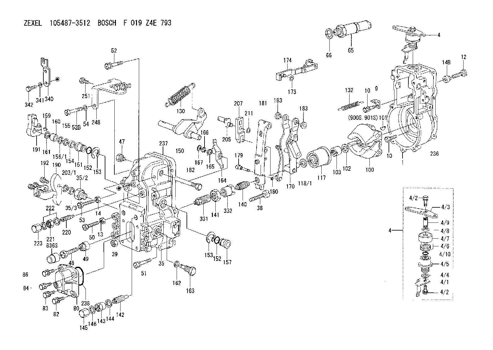
F 019 Z4E 793
f019z4e793
ZEXEL
105487-3512
1054873512
NISSAN-DIESEL
1910197309
1910197309
Rating:
Scheme ###:
| 1. | [1] | 154000-4700 | GOVERNOR HOUSING |
| 4. | [1] | 154365-3120 | CONTROL LEVER |
| 4. | [1] | 154365-3120 | CONTROL LEVER |
| 4/1. | [1] | 154304-6200 | CONTROL LEVER |
| 4/2. | [2] | 154352-2000 | BLEEDER SCREW |
| 4/2. | [2] | 154352-2000 | BLEEDER SCREW |
| 4/3. | [1] | 154304-0900 | CONTROL LEVER |
| 4/4. | [1] | 029311-0230 | SHIM D18&10.3T0.5 |
| 4/5. | [1] | 154321-1500 | BUSHING |
| 4/6. | [1] | 154327-2901 | COILED SPRING |
| 4/7. | [1] | 154322-0100 | CAP |
| 4/8. | [1] | 029311-0220 | SHIM D18&10.3T0.2 |
| 4/9. | [1] | 154324-2700 | LEVER SHAFT |
| 4/10. | [1] | 029631-0030 | O-RING &9.8W2.3 |
| 9. | [1] | 154350-6000 | PLATE |
| 10. | [8] | 020106-2040 | BLEEDER SCREW M6P1L20 |
| 10. | [8] | 020106-2040 | BLEEDER SCREW M6P1L20 |
| 12. | [1] | 154010-7200 | BLEEDER SCREW M8P1.25L62 |
| 13. | [1] | 013020-6040 | UNION NUT M6P1H5 |
| 14. | [1] | 154011-0100 | HEXAGON NUT |
| 14B. | [1] | 154011-2300 | UNION NUT |
| 35. | [1] | 154514-3920 | GOVERNOR COVER |
| 35/2. | [1] | 154321-2300 | BUSHING |
| 35/3. | [1] | 029621-0080 | PACKING RING |
| 38. | [1] | 154031-3500 | FLAT-HEAD SCREW |
| 39. | [1] | 154011-1600 | UNION NUT |
| 47. | [1] | 154036-1200 | CAPSULE |
| 48. | [1] | 154010-5500 | BLEEDER SCREW M10P1.25L42 |
| 49. | [1] | 154011-2100 | UNION NUT |
| 50. | [1] | 155615-1600 | BLEEDER SCREW |
| 51. | [4] | 020106-3840 | BLEEDER SCREW |
| 52. | [1] | 020106-5040 | BLEEDER SCREW |
| 52B. | [1] | 029010-6850 | BLEEDER SCREW |
| 53. | [1] | 154010-2900 | BLEEDER SCREW |
| 54. | [1] | 014110-6440 | LOCKING WASHER |
| 65. | [1] | 153020-4320 | STOPPING DEVICE |
| 66. | [1] | 026524-3040 | GASKET |
| 80. | [1] | 154063-8900 | COVER |
| 82. | [1] | 029020-6210 | BLEEDER SCREW |
| 83. | [1] | 020006-1640 | BLEEDER SCREW M6P1L16 4T |
| 84. | [1] | 029020-6210 | BLEEDER SCREW |
| 86. | [1] | 020006-1640 | BLEEDER SCREW M6P1L16 4T |
| 100. | [1] | 154100-9520 | FLYWEIGHT ASSEMBLY |
| 101. | [1] | 025803-1310 | WOODRUFF KEY |
| 102. | [1] | 029321-2020 | LOCKING WASHER |
| 103. | [1] | 029231-2030 | UNION NUT |
| 117. | [1] | 154123-2320 | SLIDING PIECE |
| 118/1. | [0] | 029311-0010 | SHIM D14&10.1T0.2 |
| 118/1. | [0] | 029311-0180 | SHIM D14&10.1T0.3 |
| 118/1. | [0] | 029311-0190 | SHIM D14&10.1T0.40 |
| 118/1. | [0] | 029311-0210 | SHIM D14&10.1T1 |
| 118/1. | [0] | 139410-0000 | SHIM D14.0&10.1T0.5 |
| 118/1. | [0] | 139410-0100 | SHIM D14.0&10.1T1.5 |
| 118/1. | [0] | 139410-3000 | SHIM D14&10.1T2.0 |
| 118/1. | [0] | 139410-3100 | SHIM D14&10.1T3.0 |
| 118/1. | [0] | 139410-3200 | SHIM D14&10.1T4.0 |
| 130. | [1] | 154150-7500 | GOVERNOR SPRING |
| 132. | [1] | 154154-0200 | COILED SPRING |
| 140. | [1] | 154180-3720 | HEADLESS SCREW |
| 141. | [1] | 029201-6010 | UNION NUT |
| 142. | [1] | 154242-3120 | HEADLESS SCREW |
| 143. | [1] | 154242-3200 | UNION NUT |
| 144. | [1] | 026516-2040 | GASKET D19.9&16.2T1 |
| 145. | [1] | 154159-1800 | CAP NUT |
| 146. | [1] | 029331-6130 | GASKET |
| 150. | [1] | 154200-3701 | SWIVELLING LEVER |
| 151. | [1] | 154204-2001 | BUSHING |
| 152. | [2] | 029631-8020 | O-RING |
| 152. | [2] | 029631-8020 | O-RING |
| 153. | [2] | 154354-3900 | LOCKING WASHER |
| 153. | [2] | 154354-3900 | LOCKING WASHER |
| 154. | [1] | 139611-0000 | PACKING RING |
| 155. | [1] | 139411-0000 | SHIM |
| 156/1. | [0] | 029311-1110 | SHIM D17&11T0.1 |
| 156/1. | [0] | 029311-1120 | SHIM D17&11T0.2 |
| 156/1. | [0] | 029311-1130 | SHIM D17&11T0.3 |
| 157. | [1] | 154204-3400 | BUSHING |
| 159. | [1] | 025803-1310 | WOODRUFF KEY |
| 160. | [1] | 154206-0900 | BUSHING |
| 161. | [0] | 154206-0200 | PLAIN WASHER D19.5&11.2T1.0 |
| 162. | [1] | 029331-6050 | GASKET |
| 163. | [1] | 154401-3401 | BLEEDER SCREW |
| 164. | [1] | 154243-0620 | CONTROL LEVER |
| 165. | [1] | 154327-5400 | COILED SPRING |
| 166. | [1] | 029310-8320 | SHIM D16.5&8T0.2 |
| 167. | [1] | 154356-3600 | LOCKING WASHER |
| 170. | [1] | 154211-7220 | FORK LEVER |
| 173. | [1] | 016010-0540 | LOCKING WASHER |
| 174. | [1] | 154230-4920 | STRAP |
| 179. | [1] | 154238-0301 | BEARING PIN |
| 180. | [1] | 016010-0540 | LOCKING WASHER |
| 181. | [1] | 154236-7021 | TENSIONING LEVER |
| 182. | [1] | 154237-0900 | BEARING PIN |
| 183. | [2] | 154237-0600 | BUSHING |
| 183. | [2] | 154237-0600 | BUSHING |
| 190. | [1] | 154362-0120 | CONTROL LEVER |
| 191. | [1] | 154340-5321 | CONTROL LEVER |
| 192. | [1] | 020006-1670 | BLEEDER SCREW M6P1L16 7T |
| 203/1. | [0] | 139410-0200 | SHIM D32&10.2T0.1 |
| 203/1. | [0] | 139410-0300 | SHIM D32&10.2T0.3 |
| 203/1. | [0] | 139410-0400 | SHIM D32&10.2T0.5 |
| 203/1. | [0] | 139410-0500 | SHIM D32&10.2T0.9 |
| 205. | [1] | 154324-3100 | LEVER SHAFT |
| 207. | [1] | 154326-0300 | CONTROL LEVER |
| 211. | [1] | 016010-0840 | LOCKING WASHER |
| 220. | [1] | 154050-8420 | HEADLESS SCREW |
| 221. | [1] | 029201-2130 | UNION NUT M12P1.0H6 |
| 222. | [2] | 026512-1540 | GASKET D15.4&12.2T1.50 |
| 223. | [1] | 154159-1200 | CAP NUT |
| 236. | [1] | 154371-5600 | GASKET |
| 237. | [1] | 154390-0300 | GASKET |
| 238. | [1] | 029635-2020 | O-RING |
| 248. | [1] | 154359-6520 | BRACKET |
| 251. | [1] | 020106-1240 | BLEEDER SCREW M6P1.0L12 |
| 331. | [1] | 154179-0120 | HEADLESS SCREW |
| 332. | [1] | 029201-6220 | UNION NUT |
| 340. | [1] | 154370-4700 | PLATE |
| 341. | [2] | 014110-8440 | LOCKING WASHER |
| 342. | [2] | 010008-1440 | BLEEDER SCREW |
| 836S. | [1] | 154062-1700 | CAP D20L32 |
| 900S. | [1] | 025803-1310 | WOODRUFF KEY |
| 901S. | [1] | 025803-1610 | WOODRUFF KEY |
Cross reference number
Zexel num
Bosch num
Firm num
Name
Information:
Start By:a. remove fuel injection lines 1. Remove the plug, and move the race until Tool (A) can be installed to hold the rack in the center position. The rack must be in the center position to remove the fuel injection pumps.
To prevent possible personal injury carefully follow the steps below.
2. Put Tool (B), except for the 8T5287 Wrench, in position on the fuel pump housing as shown. Lower the handle to center the adjusting screw with the fuel line seat. With the handle down in the locked position, the adjusting screw must just be in contact with fuel line seat (1). If force is needed to lower the handle or there is a gap, remove the tooling, and make an adjustment to the screw.3. Loosen bushing (2) 1/4 of a turn.4. Put Tool (B) in position on the pump housing with the handle down in the locked position as shown.5. Remove bushing (2) from the pump housing.6. Carefully and slowly lift the handle to release the spring force. Remove the tooling. 7. Install Tool (C) on fuel pump (4) as shown.8. Remove seal (3) and fuel pump (4) from the fuel pump housing. 9. Remove spacers (5) from the pump housing. There must be a pump installed on either side of the pump to be removed to install Tool (B). If there is no pump, take a pump already removed, and remove the spring so there will be no spring force, and install it in the pump housing. See Install Fuel Pump. Spacers (5) are the same thickness for each fuel injection pump so they can be mixed. The fuel injection pump plungers and barrels are sets and cannot be mixed.Install Fuel Injection Pumps
1. Install spacers (5) in the fuel pump housing.2. Move the rack until Tool (A) can be installed to hold the rack in the center position. The rack must be in the center position to install the fuel injection pumps.3. Install a fuel pump without its spring so that Tool (B) can be installed. See Step 5 for correct fuel pump installation. 4. Install Tool (C) on the bonnet of the fuel pump as shown.5. Install the fuel pump in the pump housing with the saw cut (slot) (9) in the gear in alignment with small pin (6) in the lifter assembly and groove (8) in the barrel in alignment with large pin (7) in the pump housing. 6. Install the seal and bushing (2) on the fuel pump.7. Put Tool (B) in position on the fuel pump housing as shown.8. Lower the handle slowly and carefully. If the fuel pump is not installed correctly, the handle will not go all the way down. Do not try to use force on it. Remove and install the tooling and the fuel pump again.9. Make sure the seal is in its correct position, and start to tighten bushing (2). Remove the tooling, and tighten the bushing to a torque of 260 15 N m (190