Information governor
BOSCH
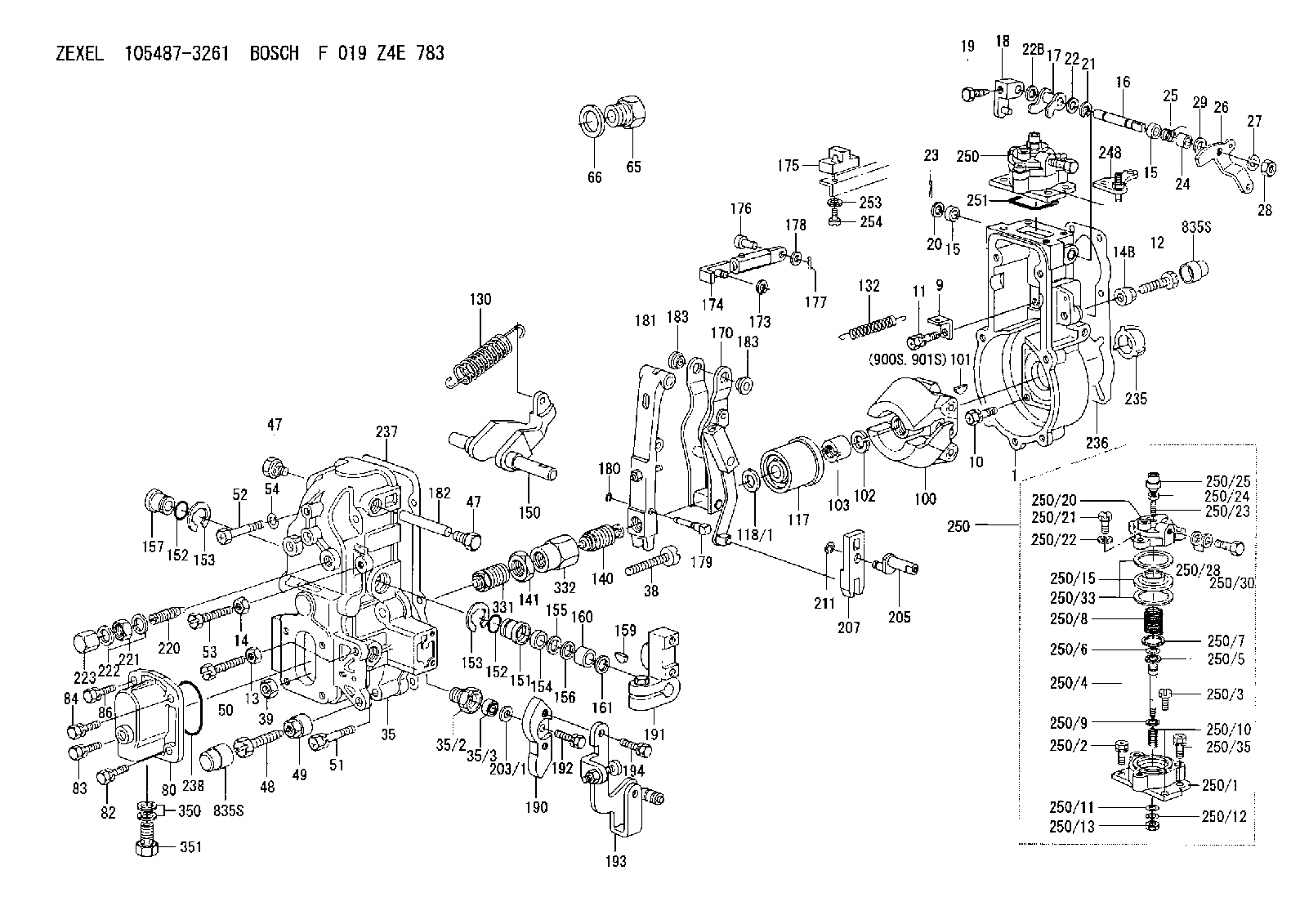
F 019 Z4E 783
f019z4e783
ZEXEL
105487-3261
1054873261
MITSUBISHI
ME726586
me726586
Rating:
Scheme ###:
| 1. | [1] | 154004-1022 | GOVERNOR HOUSING |
| 9. | [1] | 154350-6000 | PLATE |
| 10. | [4] | 020106-2040 | BLEEDER SCREW M6P1L20 |
| 11. | [4] | 020106-1840 | BLEEDER SCREW M6P1L18 |
| 12. | [1] | 154010-7300 | BLEEDER SCREW M8P1.25L60 |
| 13. | [1] | 013020-6040 | UNION NUT M6P1H5 |
| 14. | [1] | 013020-8040 | UNION NUT M8P1.25H7 |
| 14B. | [1] | 154011-2300 | UNION NUT |
| 15. | [2] | 029620-8050 | PACKING RING |
| 15. | [2] | 029620-8050 | PACKING RING |
| 16. | [1] | 155004-3301 | LEVER SHAFT |
| 17. | [1] | 154408-1520 | CONTROL LEVER |
| 18. | [1] | 155003-1920 | CONTROL LEVER |
| 19. | [1] | 155006-0700 | BLEEDER SCREW |
| 20. | [1] | 139308-0900 | PLAIN WASHER D16&8T1 |
| 20B. | [1] | 139308-1000 | PLAIN WASHER D16&8T1.5 |
| 21. | [1] | 016010-0740 | LOCKING WASHER |
| 22. | [0] | 029310-8040 | SHIM D13.5&8T0.2 |
| 22B. | [0] | 029310-8050 | SHIM D13.5&8T0.5 |
| 23. | [1] | 025520-1210 | SPLIT PIN |
| 24. | [1] | 154206-2000 | BUSHING |
| 25. | [1] | 154327-5200 | COILED SPRING |
| 26. | [1] | 154365-2400 | CONTROL LEVER |
| 27. | [1] | 014110-8440 | LOCKING WASHER |
| 28. | [1] | 013020-8040 | UNION NUT M8P1.25H7 |
| 29. | [1] | 139408-1400 | SHIM |
| 29B. | [0] | 139408-1400 | SHIM |
| 29C. | [0] | 139408-1500 | SHIM |
| 35. | [1] | 154513-5820 | GOVERNOR COVER |
| 35/2. | [1] | 154321-2000 | BUSHING |
| 35/3. | [1] | 029621-0080 | PACKING RING |
| 38. | [1] | 154031-3401 | FLAT-HEAD SCREW |
| 39. | [1] | 029201-0160 | UNION NUT |
| 47. | [2] | 154036-1800 | CAPSULE |
| 47. | [2] | 154036-1800 | CAPSULE |
| 48. | [1] | 154010-7100 | BLEEDER SCREW M10P1.25L47 |
| 48B. | [1] | 154010-8200 | BLEEDER SCREW |
| 49. | [1] | 154011-2200 | UNION NUT |
| 50. | [1] | 155615-1900 | BLEEDER SCREW |
| 51. | [5] | 020106-4540 | BLEEDER SCREW M6P1.0L45 |
| 52. | [2] | 029010-6850 | BLEEDER SCREW |
| 53. | [1] | 154010-7300 | BLEEDER SCREW M8P1.25L60 |
| 54. | [2] | 014110-6440 | LOCKING WASHER |
| 65. | [1] | 155404-1700 | CAP |
| 66. | [1] | 026524-3040 | GASKET |
| 80. | [1] | 154063-6121 | COVER |
| 82. | [1] | 029020-6210 | BLEEDER SCREW |
| 83. | [1] | 020006-1640 | BLEEDER SCREW M6P1L16 4T |
| 84. | [1] | 029020-6210 | BLEEDER SCREW |
| 86. | [1] | 020006-1640 | BLEEDER SCREW M6P1L16 4T |
| 100. | [1] | 154100-9220 | FLYWEIGHT ASSEMBLY |
| 101. | [1] | 025803-1310 | WOODRUFF KEY |
| 102. | [1] | 029321-2020 | LOCKING WASHER |
| 103. | [1] | 139212-0000 | UNION NUT |
| 117. | [1] | 154123-2320 | SLIDING PIECE |
| 118/1. | [0] | 029311-0010 | SHIM D14&10.1T0.2 |
| 118/1. | [0] | 029311-0180 | SHIM D14&10.1T0.3 |
| 118/1. | [0] | 029311-0190 | SHIM D14&10.1T0.40 |
| 118/1. | [0] | 029311-0210 | SHIM D14&10.1T1 |
| 118/1. | [0] | 139410-0000 | SHIM D14.0&10.1T0.5 |
| 118/1. | [0] | 139410-0100 | SHIM D14.0&10.1T1.5 |
| 118/1. | [0] | 139410-3000 | SHIM D14&10.1T2.0 |
| 118/1. | [0] | 139410-3100 | SHIM D14&10.1T3.0 |
| 118/1. | [0] | 139410-3200 | SHIM D14&10.1T4.0 |
| 130. | [1] | 154150-7900 | GOVERNOR SPRING |
| 132. | [1] | 154154-0701 | COILED SPRING |
| 140. | [1] | 154183-0420 | HEADLESS SCREW |
| 141. | [1] | 139218-0100 | UNION NUT |
| 150. | [1] | 154200-5401 | SWIVELLING LEVER |
| 151. | [1] | 154200-5501 | BUSHING |
| 152. | [2] | 139700-0000 | O-RING |
| 152. | [2] | 139700-0000 | O-RING |
| 153. | [2] | 154354-3900 | LOCKING WASHER |
| 153. | [2] | 154354-3900 | LOCKING WASHER |
| 154. | [1] | 139610-0101 | PACKING RING |
| 155. | [1] | 139411-0100 | SHIM D22.0&12.0T0.40 |
| 156. | [0] | 139411-0200 | SHIM D18.0&12.0T0.10 |
| 156B. | [0] | 139411-0300 | SHIM D18.0&12.0T0.20 |
| 156C. | [0] | 139411-0400 | SHIM D18.0&12.0T0.30 |
| 157. | [1] | 154204-3500 | BUSHING |
| 159. | [1] | 025803-1310 | WOODRUFF KEY |
| 160. | [1] | 154206-2300 | BUSHING |
| 161. | [0] | 154206-2400 | PLAIN WASHER D20.5&12.2T1 |
| 170. | [1] | 154216-1920 | FORK LEVER |
| 173. | [1] | 016010-0540 | LOCKING WASHER |
| 174. | [1] | 154234-0320 | STRAP |
| 175. | [1] | 154232-1720 | PLATE |
| 176. | [1] | 159231-4900 | BEARING PIN |
| 177. | [1] | 155402-3800 | SAFETY PIN |
| 178. | [1] | 029310-5170 | SHIM D8&5.3T0.5 |
| 179. | [1] | 154238-0201 | BEARING PIN |
| 180. | [1] | 016010-0540 | LOCKING WASHER |
| 181. | [1] | 154236-5200 | TENSIONING LEVER |
| 182. | [1] | 154237-1200 | BEARING PIN |
| 183. | [2] | 154237-1300 | BUSHING |
| 183. | [2] | 154237-1300 | BUSHING |
| 190. | [1] | 154360-2800 | CONTROL LEVER |
| 191. | [1] | 154340-1920 | CONTROL LEVER |
| 192. | [1] | 020006-1670 | BLEEDER SCREW M6P1L16 7T |
| 193. | [1] | 154363-6820 | CONTROL LEVER |
| 194. | [2] | 020006-1240 | BLEEDER SCREW M6P1L12 4T |
| 203/1. | [0] | 029311-0640 | SHIM D26.0&10.2T0.95 |
| 203/1. | [0] | 029311-0650 | SHIM D26.0&10.2T0.20 |
| 203/1. | [0] | 029311-0660 | SHIM D26.0&10.2T0.25 |
| 203/1. | [0] | 029311-0670 | SHIM D26.0&10.2T0.30 |
| 203/1. | [0] | 029311-0680 | SHIM D26.0&10.2T0.35 |
| 203/1. | [0] | 029311-0690 | SHIM D26.0&10.2T0.40 |
| 203/1. | [0] | 029311-0700 | SHIM D26.0&10.2T0.50 |
| 203/1. | [0] | 139410-1400 | SHIM D26&10.2T0.7 |
| 203/1. | [0] | 139410-1500 | SHIM D26&10.2T0.9 |
| 203/1. | [0] | 139410-1600 | SHIM D26&10.2T0.8 |
| 203/1. | [0] | 139410-2700 | SHIM D26&10.2T0.6 |
| 205. | [1] | 154324-2900 | LEVER SHAFT |
| 207. | [1] | 154326-0300 | CONTROL LEVER |
| 211. | [1] | 016010-0840 | LOCKING WASHER |
| 220. | [1] | 154050-6220 | HEADLESS SCREW |
| 221. | [1] | 029201-2140 | UNION NUT |
| 222. | [2] | 026512-1540 | GASKET D15.4&12.2T1.50 |
| 223. | [1] | 154159-1200 | CAP NUT |
| 235. | [1] | 155412-5200 | IMPELLER WHEEL |
| 236. | [1] | 154371-5600 | GASKET |
| 237. | [1] | 154390-0200 | GASKET |
| 238. | [1] | 139700-0100 | O-RING |
| 248. | [1] | 154356-9320 | BRACKET |
| 250. | [1] | 154418-7121 | MANIFOLD-PRESSURE COMP. |
| 250. | [1] | 154418-7121 | MANIFOLD-PRESSURE COMP. |
| 250/1. | [1] | 154412-3320 | DIAPHRAGM HOUSING |
| 250/2. | [2] | 020106-1640 | BLEEDER SCREW M6P1.0L14 |
| 250/3. | [1] | 029020-6260 | BLEEDER SCREW |
| 250/4. | [1] | 154400-5800 | STOP PIN |
| 250/5. | [1] | 153400-0900 | SLOTTED WASHER |
| 250/6. | [1] | 016010-0740 | LOCKING WASHER |
| 250/7. | [0] | 029312-0180 | SHIM D25.5&20T0.5 |
| 250/7B. | [0] | 029312-0210 | SHIM D25.5&20T0.2 |
| 250/8. | [1] | 154411-4500 | COILED SPRING |
| 250/9. | [0] | 154355-3900 | SHIM D18&12.5T0.10 |
| 250/9B. | [0] | 154355-4000 | SHIM D18&12.5T0.20 |
| 250/9C. | [0] | 154355-4100 | SHIM D18&12.5T0.30 |
| 250/10. | [1] | 154416-5200 | COILED SPRING |
| 250/11. | [1] | 153400-0800 | SPRING SEAT |
| 250/12. | [1] | 014110-5440 | LOCKING WASHER |
| 250/13. | [1] | 013030-5240 | UNION NUT M5P0.8H3.2 |
| 250/15. | [1] | 154400-9320 | DIAPHRAGM |
| 250/20. | [1] | 154404-5100 | COVER |
| 250/21. | [3] | 029010-6310 | BLEEDER SCREW |
| 250/22. | [3] | 014110-6440 | LOCKING WASHER |
| 250/23. | [1] | 154404-5300 | FLAT-HEAD SCREW |
| 250/24. | [1] | 023040-6040 | UNION NUT |
| 250/25. | [1] | 154406-7800 | CAP NUT |
| 250/28. | [2] | 026510-1340 | GASKET D13.4&10.2T1 |
| 250/30. | [1] | 029731-0180 | EYE BOLT |
| 250/33. | [2] | 154413-2600 | GASKET |
| 250/35. | [1] | 020106-2040 | BLEEDER SCREW M6P1L20 |
| 251. | [1] | 154358-2500 | SEAL RING |
| 253. | [1] | 029320-5020 | LOCKING WASHER |
| 254. | [1] | 010535-1040 | FLAT-HEAD SCREW M5P0.8L10 |
| 331. | [1] | 154179-3120 | HEADLESS SCREW |
| 332. | [1] | 139218-0200 | UNION NUT |
| 350. | [2] | 026512-1840 | GASKET D17.9&12.2T1.50 |
| 351. | [1] | 153556-4800 | EYE BOLT |
| 835S. | [2] | 154062-1700 | CAP D20L32 |
| 835S. | [2] | 154062-1700 | CAP D20L32 |
| 900S. | [1] | 025803-1310 | WOODRUFF KEY |
| 901S. | [1] | 025803-1610 | WOODRUFF KEY |
Include in #1:
106671-7631
as GOVERNOR
Cross reference number
Zexel num
Bosch num
Firm num
Name
Information:
9. Remove bracket assembly (16) and link (17). 10. Put identification marks on fuel racks (18) and (19), and remove the fuel racks. 11. Put identification marks on each spacer (20) and lifter (21) so they can be installed in their original position. 12. Remove fuel injection pump camshaft (22) from the pump housing.13. Remove O-ring seal (23). 14. Inspect link pivot shaft (24) and bracket locating pin (25). Make a replacement by removal of shaft (24) and dowel (25) with Tool (D). 15. Inspect upper bearing (26) and the lower bearing that hold the pinion gear in the pump housing.16. Make a replacement of bearings (26) if necessary.17. Inspect idler gear shaft (27). If a replacement is necessary, remove the shaft with Tooling (D). 18. Inspect fuel rack bearings (28) and camshaft bearings (29). If a replacement is necessary, remove bearings (28) and (29).19. Use Tooling (E) to remove bearings (28). 20. Remove regulator valve (30). 21. Remove pin (31) to disassemble the regulator valve, and inspect the components.22. Piston (32) must move freely in valve body (30).23. Make a reference to the Specifications for spring (34).24. Make a replacement of O-ring seals (33).Assemble Fuel Injection Pump Housing
Pin (2) must not extend out of either side of valve body (3).
1. Install spring (4), piston (1) and pin (2) in valve body (3).2. Put clean engine oil on the valve body and O-ring seals (5). Install the oil bypass valve in the pump housing. Tighten the bypass valve body to a torque of 68 14 N m (50 10 lb ft). 3. Install the camshaft front and rear bearings with Tooling (A). Install the front bearing until it is a distance of 1.0 0.5 mm (.04 .02 in) from the front surface of the pump housing. Make sure both oil holes in bearing are in alignment with the oil holes in the pump housing. 4. Put Tool (B) in the fuel pump housing with the dowels of Tool (B) in alignment with the left fuel rack bore. Install the bolt that holds the tool in place on the housing.5. Put a new bearing in position with the tab of the bearing up. Install the bearing with Tool (C) until the shoulder of Tool (C) makes contact with Tool (B).6. Turn Tool (B), and make an alignment of the dowels on Tool (B) with the right fuel rack bore.7. Do Step 3 again for the left fuel rack bearing. 8. Install shaft (6) to a height of 16.8 0.5 mm (.66 .02 in). 9. Make sure the chamfer on the lower bearing for the pinion gear is toward the inside and the notch is in the location shown. Install the bearing 28.4 0.5 mm (1.12 .02 in) below the bearing bore surface with Tooling (D).10. Make sure the chamfer on the upper bearing for the pinion gear is toward the inside and the notch is in the location shown. Use