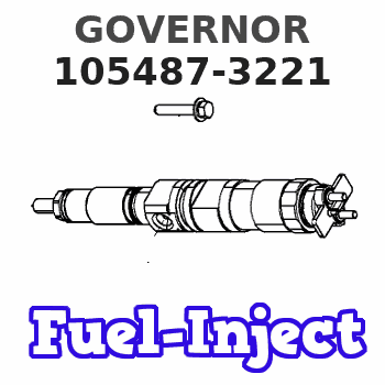
Information governor
BOSCH
F 019 Z4E 779
f019z4e779
ZEXEL
105487-3221
1054873221
MITSUBISHI
ME726583
me726583
Rating:
Scheme ###:
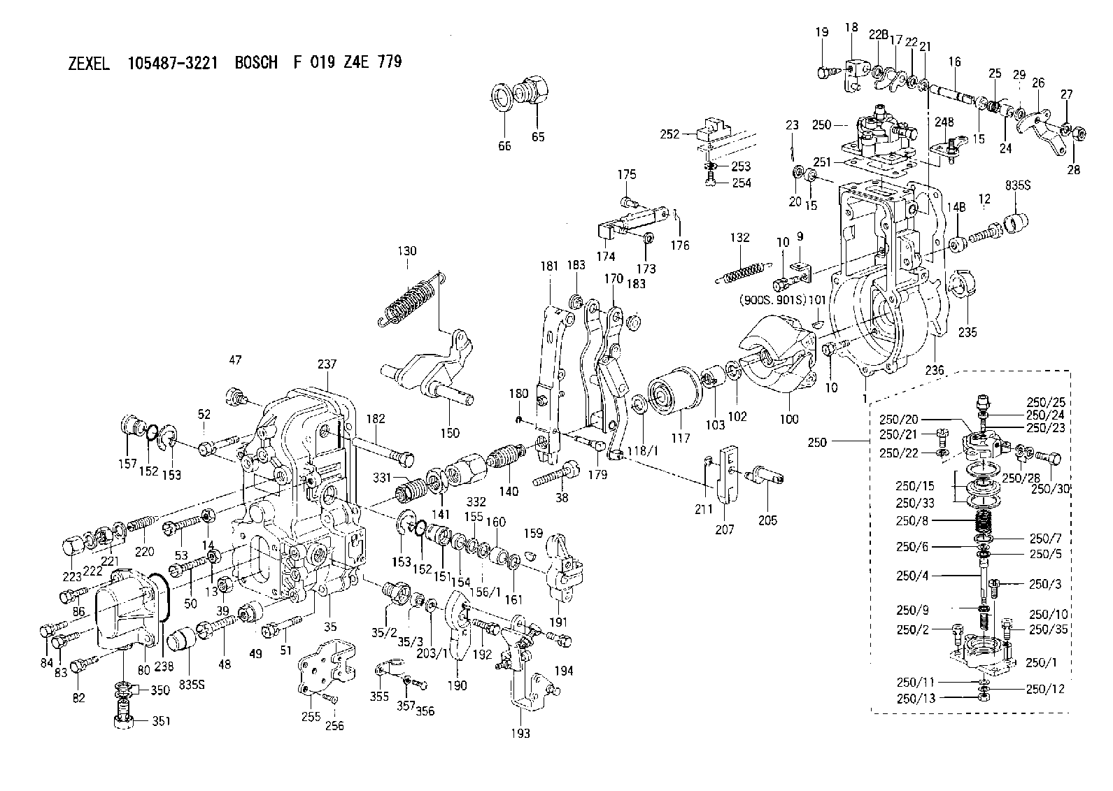
| 1. | [1] | 154004-1720 | GOVERNOR HOUSING |
| 9. | [1] | 154350-6000 | PLATE |
| 10. | [8] | 020106-2040 | BLEEDER SCREW |
| 12. | [1] | 154010-7300 | BLEEDER SCREW |
| 13. | [1] | 013020-6040 | UNION NUT |
| 14. | [1] | 013020-8040 | UNION NUT |
| 14. | [1] | 013020-8040 | UNION NUT |
| 14B. | [1] | 154011-2300 | UNION NUT |
| 15. | [2] | 029620-8050 | PACKING RING |
| 15. | [2] | 029620-8050 | PACKING RING |
| 16. | [1] | 155004-3301 | LEVER SHAFT |
| 17. | [1] | 154408-1520 | CONTROL LEVER |
| 18. | [1] | 155003-1920 | CONTROL LEVER |
| 19. | [1] | 155006-0700 | BLEEDER SCREW |
| 20. | [1] | 139308-0900 | PLAIN WASHER D16&8T1 |
| 20B. | [1] | 139308-1000 | PLAIN WASHER D16&8T1.5 |
| 21. | [1] | 016010-0740 | LOCKING WASHER |
| 22. | [0] | 029310-8040 | SHIM D13.5&8T0.2 |
| 22. | [0] | 139408-1400 | SHIM D16&8T0.2 |
| 22B. | [0] | 029310-8050 | SHIM D13.5&8T0.5 |
| 23. | [1] | 025520-1210 | SPLIT PIN |
| 24. | [1] | 154206-2000 | BUSHING |
| 25. | [1] | 154327-5200 | COILED SPRING |
| 26. | [1] | 154365-2700 | CONTROL LEVER |
| 27. | [1] | 014110-8440 | LOCKING WASHER D15.4&8.2T2 |
| 28. | [1] | 013020-8040 | UNION NUT |
| 29. | [1] | 139408-1400 | SHIM D16&8T0.2 |
| 29B. | [0] | 139408-1400 | SHIM D16&8T0.2 |
| 29C. | [0] | 139408-1500 | SHIM D16&8T0.5 |
| 35. | [1] | 154514-0420 | GOVERNOR COVER |
| 35/2. | [1] | 154321-1800 | BUSHING |
| 35/3. | [1] | 029621-0080 | PACKING RING |
| 38. | [1] | 154031-3500 | FLAT-HEAD SCREW |
| 39. | [1] | 154011-1600 | UNION NUT |
| 47. | [1] | 154036-0300 | CAPSULE |
| 48. | [1] | 154010-7100 | BLEEDER SCREW |
| 49. | [1] | 154011-2200 | UNION NUT |
| 50. | [1] | 155615-1600 | BLEEDER SCREW |
| 51. | [4] | 020106-3840 | BLEEDER SCREW |
| 52. | [2] | 020106-5040 | BLEEDER SCREW |
| 53. | [1] | 154010-7300 | BLEEDER SCREW |
| 65. | [1] | 155404-1700 | CAP |
| 66. | [1] | 026524-3040 | GASKET |
| 80. | [1] | 154063-6021 | COVER |
| 82. | [1] | 029020-6210 | BLEEDER SCREW |
| 83. | [1] | 020006-1640 | BLEEDER SCREW |
| 84. | [1] | 029020-6210 | BLEEDER SCREW |
| 86. | [1] | 020006-1640 | BLEEDER SCREW |
| 100. | [1] | 154100-9520 | FLYWEIGHT ASSEMBLY |
| 101. | [1] | 025803-1310 | WOODRUFF KEY 13 MM |
| 102. | [1] | 029321-2020 | LOCKING WASHER |
| 103. | [1] | 029231-2030 | UNION NUT |
| 117. | [1] | 154123-2320 | SLIDING PIECE |
| 118/1. | [0] | 029311-0010 | SHIM D14&10.1T0.2 |
| 118/1. | [0] | 029311-0180 | SHIM D14&10.1T0.3 |
| 118/1. | [0] | 029311-0190 | SHIM D14&10.1T0.40 |
| 118/1. | [0] | 029311-0210 | SHIM D14&10.1T1 |
| 118/1. | [0] | 139410-0000 | SHIM D14&10.1T0.5 |
| 118/1. | [0] | 139410-0100 | SHIM D14&10.1T1.5 |
| 118/1. | [0] | 139410-3000 | SHIM D14&10.1T2.0 |
| 118/1. | [0] | 139410-3100 | SHIM D14&10.1T3.0 |
| 118/1. | [0] | 139410-3200 | SHIM D14&10.1T4.0 |
| 130. | [1] | 154150-6200 | GOVERNOR SPRING |
| 132. | [1] | 154154-0200 | COILED SPRING |
| 140. | [1] | 154180-0420 | HEADLESS SCREW |
| 141. | [1] | 029201-6220 | UNION NUT |
| 150. | [1] | 154200-3801 | SWIVELLING LEVER |
| 151. | [1] | 154204-2001 | BUSHING |
| 152. | [2] | 029631-8020 | O-RING |
| 152. | [2] | 029631-8020 | O-RING |
| 153. | [2] | 154354-3900 | LOCKING WASHER |
| 153. | [2] | 154354-3900 | LOCKING WASHER |
| 154. | [1] | 139611-0000 | PACKING RING |
| 155. | [1] | 139411-0000 | SHIM |
| 156/1. | [0] | 029311-1110 | SHIM D17&11T0.1 |
| 156/1. | [0] | 029311-1120 | SHIM D17&11T0.2 |
| 156/1. | [0] | 029311-1130 | SHIM D17&11T0.3 |
| 157. | [1] | 154204-3400 | BUSHING |
| 159. | [1] | 025803-1310 | WOODRUFF KEY 13 MM |
| 160. | [1] | 154206-0900 | BUSHING |
| 161. | [0] | 154206-0200 | PLAIN WASHER D19.5&11.2T1.0 |
| 170. | [1] | 154216-2520 | GUIDE LEVER |
| 173. | [1] | 016010-0540 | LOCKING WASHER |
| 174. | [1] | 154234-2320 | STRAP |
| 175. | [1] | 159231-4900 | BEARING PIN |
| 176. | [1] | 155402-3800 | SAFETY PIN |
| 179. | [1] | 154238-0301 | BEARING PIN |
| 180. | [1] | 016010-0540 | LOCKING WASHER |
| 181. | [1] | 154236-5300 | TENSIONING LEVER |
| 182. | [1] | 154237-0900 | BEARING PIN |
| 183. | [2] | 154237-0600 | BUSHING |
| 183. | [2] | 154237-0600 | BUSHING |
| 190. | [1] | 154360-2800 | CONTROL LEVER |
| 191. | [1] | 154340-0120 | CONTROL LEVER |
| 192. | [1] | 020006-1670 | BLEEDER SCREW |
| 193. | [1] | 154368-2720 | CONTROL LEVER |
| 194. | [2] | 020006-1240 | BLEEDER SCREW |
| 203/1. | [0] | 029311-0640 | SHIM D26.0&10.2T0.95 |
| 203/1. | [0] | 029311-0650 | SHIM D26.0&10.2T0.20 |
| 203/1. | [0] | 029311-0660 | SHIM D26.0&10.2T0.25 |
| 203/1. | [0] | 029311-0670 | SHIM D26.0&10.2T0.30 |
| 203/1. | [0] | 029311-0680 | SHIM D26.0&10.2T0.35 |
| 203/1. | [0] | 029311-0690 | SHIM D26.0&10.2T0.40 |
| 203/1. | [0] | 029311-0700 | SHIM D26.0&10.2T0.50 |
| 203/1. | [0] | 139410-1400 | SHIM D26&10.2T0.7 |
| 203/1. | [0] | 139410-1500 | SHIM D26&10.2T0.9 |
| 203/1. | [0] | 139410-1600 | SHIM D26&10.2T0.8 |
| 203/1. | [0] | 139410-2700 | SHIM D26&10.2T0.6 |
| 205. | [1] | 154324-4500 | LEVER SHAFT |
| 207. | [1] | 154326-0300 | CONTROL LEVER |
| 211. | [1] | 016010-0840 | LOCKING WASHER |
| 220. | [1] | 154050-6220 | HEADLESS SCREW |
| 221. | [1] | 029201-2130 | UNION NUT |
| 222. | [2] | 026512-1540 | GASKET |
| 223. | [1] | 154159-1200 | CAP NUT |
| 235. | [1] | 155412-5200 | IMPELLER WHEEL |
| 236. | [1] | 154371-5600 | GASKET |
| 237. | [1] | 154390-0300 | GASKET |
| 238. | [1] | 029635-2020 | O-RING |
| 248. | [1] | 154356-9320 | BRACKET |
| 250. | [1] | 154417-5721 | MANIFOLD-PRESSURE COMP. |
| 250. | [1] | 154417-5721 | MANIFOLD-PRESSURE COMP. |
| 250/1. | [1] | 154412-3320 | DIAPHRAGM HOUSING |
| 250/2. | [2] | 020106-1640 | BLEEDER SCREW |
| 250/3. | [1] | 029020-6260 | BLEEDER SCREW |
| 250/4. | [1] | 154400-5101 | STOP PIN |
| 250/5. | [1] | 153400-0900 | SLOTTED WASHER |
| 250/6. | [1] | 016010-0740 | LOCKING WASHER |
| 250/7. | [0] | 029312-0180 | SHIM D25.5&20T0.5 |
| 250/7B. | [0] | 029312-0210 | SHIM D25.5&20T0.2 |
| 250/8. | [1] | 154411-2000 | COILED SPRING |
| 250/9. | [0] | 154355-3900 | SHIM D18&12.5T0.10 |
| 250/9B. | [0] | 154355-4000 | SHIM D18&12.5T0.20 |
| 250/9C. | [0] | 154355-4100 | SHIM D18&12.5T0.30 |
| 250/10. | [1] | 154411-1400 | COILED SPRING |
| 250/11. | [1] | 153400-0800 | SPRING SEAT |
| 250/12. | [1] | 014110-5440 | LOCKING WASHER |
| 250/13. | [1] | 013030-5240 | UNION NUT |
| 250/15. | [1] | 154400-9320 | DIAPHRAGM |
| 250/20. | [1] | 154404-5100 | COVER |
| 250/21. | [3] | 029010-6310 | BLEEDER SCREW |
| 250/22. | [3] | 014110-6440 | LOCKING WASHER D12.2&6.1T1.5 |
| 250/23. | [1] | 154404-5300 | FLAT-HEAD SCREW |
| 250/24. | [1] | 023040-6040 | UNION NUT |
| 250/25. | [1] | 154406-7800 | CAP NUT |
| 250/28. | [2] | 026510-1340 | GASKET |
| 250/30. | [1] | 029731-0180 | EYE BOLT |
| 250/33. | [2] | 154413-2600 | GASKET |
| 250/35. | [1] | 020106-2040 | BLEEDER SCREW |
| 251. | [1] | 154390-2000 | GASKET |
| 252. | [1] | 154232-1220 | PLATE |
| 253. | [1] | 029320-5020 | LOCKING WASHER |
| 254. | [1] | 010535-1040 | FLAT-HEAD SCREW |
| 255. | [1] | 154356-2200 | BRACKET |
| 256. | [3] | 021305-0940 | FLAT-HEAD SCREW |
| 331. | [1] | 154179-2920 | HEADLESS SCREW |
| 332. | [1] | 029201-6010 | UNION NUT |
| 350. | [2] | 026512-1840 | GASKET |
| 351. | [1] | 153556-4800 | EYE BOLT |
| 355. | [1] | 154604-0200 | CLAMPING BAND |
| 356. | [1] | 012554-0840 | FLAT-HEAD SCREW |
| 357. | [1] | 014010-4140 | PLAIN WASHER |
| 835S. | [2] | 154062-1700 | CAP |
| 835S. | [2] | 154062-1700 | CAP |
| 900S. | [1] | 025803-1310 | WOODRUFF KEY 13 MM |
| 901S. | [1] | 025803-1610 | WOODRUFF KEY 16 MM |
Include in #1:
106651-2331
as GOVERNOR
Cross reference number
Zexel num
Bosch num
Firm num
Name
Information:
1. Remove the bolt and lock that holds suction bell (1) to the oil pan plate. Remove two bolts (4) that hold the elbow to the oil pump.
Oil pump idler gear (2) can fall off the pump when the pump is removed. To prevent injury, always hold the gear on the pump when the pump is removed.
2. Remove the bolts and locks that hold the oil pump to the engine. Remove oil pump (3).3. Install idler gear (2) on oil pump (3). Put the oil pump in position on the engine as shown with idler gear (2) engaged with the crankshaft gear. Install the bolts and locks that hold the oil pump to the engine.4. Install bolts (4) that hold the elbow to the oil pump.5. Install the bolt and lock that hold suction bell (1) to the oil pan plate.End By:a. install oil panDisassemble Oil Pump
Start By:a. remove oil pump (3304) or remove oil pump (3306) 1. Remove idler gear (2). Remove the bearing from the idler gear with Tool (B).2. Remove suction bell (1).3. Remove the bolt and the washer from the oil pump drive gear. 4. Remove the drive gear from the shaft with Tool (A).5. Remove the key from the pump shaft.6. Remove bolts (3) from the pump body. 7. Remove body (8), two gears (7), the keys and spacer (4) from the pump.8. Remove two shafts (5) and the gears.9. Remove bolts (6), the cover and the pressure relief valve from the body. 10. Remove the bearings from the oil pump body assembly and the scavenge pump body assembly with Tool (B).Assemble Oil Pump
1. Install the bearings in the scavenge pump body assembly with Tool (A) and a press as follows:a. Put bearings (1) in position on the inside of the scavenge pump body assembly with the chamfer on the bearing toward the outside of the pump body. Install the bearing until it is 1.52 mm (.060 in) below the inside machined surface of the scavenge pump body assembly. Make sure the joints in the bearings are at an angle of 30° 15° from the center line through the bores in the scavenge pump body and toward the outlet passage of the pump. The outlet passage has a cavity between the bearing bores. 2. Install the bearings in oil pump body assembly with Tool (A) and a press as follows:a. Put bearings (2) in position on the inside of the oil pump body assembly with the chamfer on the bearings toward the outside of the pump body. Install the bearings until they are even with the outside of the pump body. Make sure the joints in the bearings are at an angle of 30° 15° from the centerline through the bearing bores and toward the outlet passage of the pump. The outlet passage has a cavity between the bearing bores.3. Check the condition of the relief valve. Check the condition and specifications for all the parts of the oil pump before