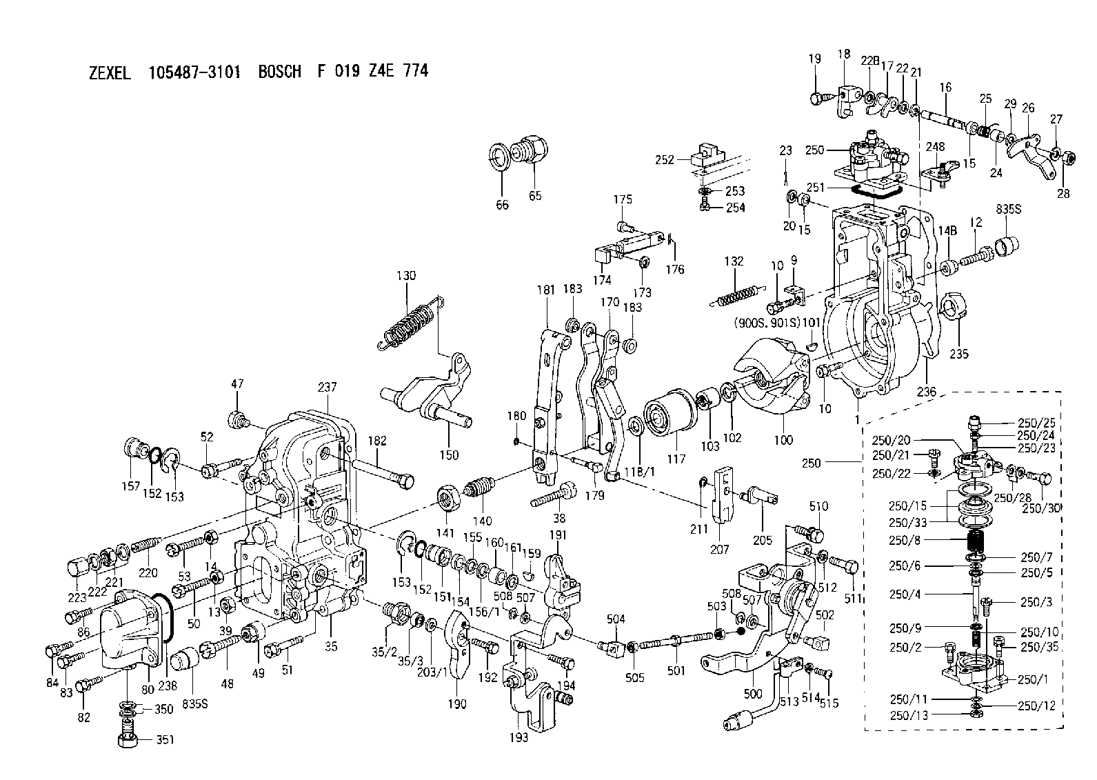
Information governor
BOSCH
F 019 Z4E 774
f019z4e774
ZEXEL
105487-3101
1054873101
MITSUBISHI
ME726277
me726277

Rating:
Scheme ###:
| 1. | [1] | 154004-1720 | GOVERNOR HOUSING |
| 9. | [1] | 154350-6000 | PLATE |
| 10. | [8] | 020106-2040 | BLEEDER SCREW |
| 10. | [8] | 020106-2040 | BLEEDER SCREW |
| 12. | [1] | 154010-7300 | BLEEDER SCREW |
| 13. | [1] | 013020-6040 | UNION NUT |
| 14. | [1] | 013020-8040 | UNION NUT |
| 14B. | [1] | 154011-2300 | UNION NUT |
| 15. | [2] | 029620-8050 | PACKING RING |
| 15. | [2] | 029620-8050 | PACKING RING |
| 16. | [1] | 155004-3301 | LEVER SHAFT |
| 17. | [1] | 154408-1520 | CONTROL LEVER |
| 18. | [1] | 155003-1920 | CONTROL LEVER |
| 19. | [1] | 155006-0700 | BLEEDER SCREW |
| 20. | [1] | 139308-0900 | PLAIN WASHER D16&8T1 |
| 20B. | [1] | 139308-1000 | PLAIN WASHER D16&8T1.5 |
| 21. | [1] | 016010-0740 | LOCKING WASHER |
| 22. | [0] | 029310-8040 | SHIM D13.5&8T0.2 |
| 22. | [0] | 139408-1400 | SHIM D16&8T0.2 |
| 22B. | [0] | 029310-8050 | SHIM D13.5&8T0.5 |
| 23. | [1] | 025520-1210 | SPLIT PIN |
| 24. | [1] | 154206-2000 | BUSHING |
| 25. | [1] | 154327-5200 | COILED SPRING |
| 26. | [1] | 154365-2500 | CONTROL LEVER |
| 27. | [1] | 014110-8440 | LOCKING WASHER D15.4&8.2T2 |
| 28. | [1] | 013020-8040 | UNION NUT |
| 29. | [1] | 139408-1400 | SHIM D16&8T0.2 |
| 29B. | [0] | 139408-1400 | SHIM D16&8T0.2 |
| 29C. | [0] | 139408-1500 | SHIM D16&8T0.5 |
| 35. | [1] | 154513-9920 | GOVERNOR COVER |
| 35/2. | [1] | 154321-1800 | BUSHING |
| 35/3. | [1] | 029621-0080 | PACKING RING |
| 38. | [1] | 154031-3500 | FLAT-HEAD SCREW |
| 39. | [1] | 154011-1600 | UNION NUT |
| 47. | [1] | 154036-0300 | CAPSULE |
| 48. | [1] | 154010-7100 | BLEEDER SCREW |
| 49. | [1] | 154011-2200 | UNION NUT |
| 50. | [1] | 155615-1900 | BLEEDER SCREW |
| 51. | [4] | 020106-3840 | BLEEDER SCREW |
| 52. | [2] | 020106-5040 | BLEEDER SCREW |
| 53. | [1] | 154010-7300 | BLEEDER SCREW |
| 65. | [1] | 155404-1700 | CAP |
| 66. | [1] | 026524-3040 | GASKET |
| 80. | [1] | 154063-6021 | COVER |
| 82. | [1] | 029020-6210 | BLEEDER SCREW |
| 83. | [1] | 020006-1640 | BLEEDER SCREW |
| 84. | [1] | 029020-6210 | BLEEDER SCREW |
| 86. | [1] | 020006-1640 | BLEEDER SCREW |
| 100. | [1] | 154100-9620 | FLYWEIGHT ASSEMBLY |
| 101. | [1] | 025803-1310 | WOODRUFF KEY 13 MM |
| 102. | [1] | 029321-2020 | LOCKING WASHER |
| 103. | [1] | 029231-2030 | UNION NUT |
| 117. | [1] | 154123-2320 | SLIDING PIECE |
| 118/1. | [0] | 029311-0010 | SHIM D14&10.1T0.2 |
| 118/1. | [0] | 029311-0180 | SHIM D14&10.1T0.3 |
| 118/1. | [0] | 029311-0190 | SHIM D14&10.1T0.40 |
| 118/1. | [0] | 029311-0210 | SHIM D14&10.1T1 |
| 118/1. | [0] | 139410-0000 | SHIM D14&10.1T0.5 |
| 118/1. | [0] | 139410-0100 | SHIM D14&10.1T1.5 |
| 118/1. | [0] | 139410-3000 | SHIM D14&10.1T2.0 |
| 118/1. | [0] | 139410-3100 | SHIM D14&10.1T3.0 |
| 118/1. | [0] | 139410-3200 | SHIM D14&10.1T4.0 |
| 130. | [1] | 154150-6200 | GOVERNOR SPRING |
| 132. | [1] | 154154-0200 | COILED SPRING |
| 140. | [1] | 154178-2120 | HEADLESS SCREW |
| 141. | [1] | 029201-6010 | UNION NUT |
| 150. | [1] | 154200-3801 | SWIVELLING LEVER |
| 151. | [1] | 154204-2001 | BUSHING |
| 152. | [2] | 029631-8020 | O-RING |
| 152. | [2] | 029631-8020 | O-RING |
| 153. | [2] | 154354-3900 | LOCKING WASHER |
| 153. | [2] | 154354-3900 | LOCKING WASHER |
| 154. | [1] | 139611-0000 | PACKING RING |
| 155. | [1] | 139411-0000 | SHIM |
| 156/1. | [0] | 029311-1110 | SHIM D17&11T0.1 |
| 156/1. | [0] | 029311-1120 | SHIM D17&11T0.2 |
| 156/1. | [0] | 029311-1130 | SHIM D17&11T0.3 |
| 157. | [1] | 154204-3400 | BUSHING |
| 159. | [1] | 025803-1310 | WOODRUFF KEY 13 MM |
| 160. | [1] | 154206-0900 | BUSHING |
| 161. | [0] | 154206-0200 | PLAIN WASHER D19.5&11.2T1.0 |
| 170. | [1] | 154216-2520 | GUIDE LEVER |
| 173. | [1] | 016010-0540 | LOCKING WASHER |
| 174. | [1] | 154234-2920 | STRAP |
| 175. | [1] | 159231-4900 | BEARING PIN |
| 176. | [1] | 155402-3800 | SAFETY PIN |
| 179. | [1] | 154238-0301 | BEARING PIN |
| 180. | [1] | 016010-0540 | LOCKING WASHER |
| 181. | [1] | 154236-5300 | TENSIONING LEVER |
| 182. | [1] | 154237-0900 | BEARING PIN |
| 183. | [2] | 154237-0600 | BUSHING |
| 183. | [2] | 154237-0600 | BUSHING |
| 190. | [1] | 154360-2800 | CONTROL LEVER |
| 191. | [1] | 154340-0120 | CONTROL LEVER |
| 192. | [1] | 020006-1670 | BLEEDER SCREW |
| 193. | [1] | 154368-3020 | CONTROL LEVER |
| 194. | [2] | 020006-1240 | BLEEDER SCREW |
| 203/1. | [0] | 029311-0640 | SHIM D26.0&10.2T0.95 |
| 203/1. | [0] | 029311-0650 | SHIM D26.0&10.2T0.20 |
| 203/1. | [0] | 029311-0660 | SHIM D26.0&10.2T0.25 |
| 203/1. | [0] | 029311-0670 | SHIM D26.0&10.2T0.30 |
| 203/1. | [0] | 029311-0680 | SHIM D26.0&10.2T0.35 |
| 203/1. | [0] | 029311-0690 | SHIM D26.0&10.2T0.40 |
| 203/1. | [0] | 029311-0700 | SHIM D26.0&10.2T0.50 |
| 203/1. | [0] | 139410-1400 | SHIM D26&10.2T0.7 |
| 203/1. | [0] | 139410-1500 | SHIM D26&10.2T0.9 |
| 203/1. | [0] | 139410-1600 | SHIM D26&10.2T0.8 |
| 203/1. | [0] | 139410-2700 | SHIM D26&10.2T0.6 |
| 205. | [1] | 154324-3000 | LEVER SHAFT |
| 207. | [1] | 154326-0300 | CONTROL LEVER |
| 211. | [1] | 016010-0840 | LOCKING WASHER |
| 220. | [1] | 154050-6220 | HEADLESS SCREW |
| 221. | [1] | 029201-2130 | UNION NUT |
| 222. | [2] | 026512-1540 | GASKET |
| 223. | [1] | 154159-1200 | CAP NUT |
| 235. | [1] | 155412-5200 | IMPELLER WHEEL |
| 236. | [1] | 154371-5600 | GASKET |
| 237. | [1] | 154390-0300 | GASKET |
| 238. | [1] | 029635-2020 | O-RING |
| 248. | [1] | 154356-9320 | BRACKET |
| 250. | [1] | 154417-0321 | MANIFOLD-PRESSURE COMP. |
| 250. | [1] | 154417-0321 | MANIFOLD-PRESSURE COMP. |
| 250/1. | [1] | 154408-6220 | DIAPHRAGM HOUSING |
| 250/2. | [2] | 020106-1640 | BLEEDER SCREW |
| 250/3. | [1] | 029020-6260 | BLEEDER SCREW |
| 250/4. | [1] | 154400-5101 | STOP PIN |
| 250/5. | [1] | 153400-0900 | SLOTTED WASHER |
| 250/6. | [1] | 016010-0740 | LOCKING WASHER |
| 250/7. | [0] | 029312-0180 | SHIM D25.5&20T0.5 |
| 250/7B. | [0] | 029312-0210 | SHIM D25.5&20T0.2 |
| 250/8. | [1] | 154403-9500 | COILED SPRING |
| 250/9. | [0] | 154355-3900 | SHIM D18&12.5T0.10 |
| 250/9B. | [0] | 154355-4000 | SHIM D18&12.5T0.20 |
| 250/9C. | [0] | 154355-4100 | SHIM D18&12.5T0.30 |
| 250/10. | [1] | 154411-2200 | COILED SPRING |
| 250/11. | [1] | 153400-0800 | SPRING SEAT |
| 250/12. | [1] | 014110-5440 | LOCKING WASHER |
| 250/13. | [1] | 013030-5240 | UNION NUT |
| 250/15. | [1] | 154400-9320 | DIAPHRAGM |
| 250/20. | [1] | 154404-5100 | COVER |
| 250/21. | [3] | 029010-6310 | BLEEDER SCREW |
| 250/22. | [3] | 014110-6440 | LOCKING WASHER D12.2&6.1T1.5 |
| 250/23. | [1] | 154404-5300 | FLAT-HEAD SCREW |
| 250/24. | [1] | 023040-6040 | UNION NUT |
| 250/25. | [1] | 154406-7800 | CAP NUT |
| 250/28. | [2] | 026510-1340 | GASKET |
| 250/30. | [1] | 029731-0180 | EYE BOLT |
| 250/33. | [2] | 154413-2600 | GASKET |
| 250/35. | [1] | 020106-2040 | BLEEDER SCREW |
| 251. | [1] | 154390-2000 | GASKET |
| 252. | [1] | 154232-1220 | PLATE |
| 253. | [1] | 029320-5020 | LOCKING WASHER |
| 254. | [1] | 010535-1040 | FLAT-HEAD SCREW |
| 350. | [2] | 026512-1840 | GASKET |
| 351. | [1] | 153556-4800 | EYE BOLT |
| 500. | [1] | 154600-6120 | LOAD SENSOR ASSY |
| 501. | [1] | 154604-2500 | LEVER SHAFT |
| 502. | [1] | 154604-1700 | BEARING PIN |
| 503. | [1] | 013020-5240 | UNION NUT |
| 504. | [1] | 154604-1800 | BEARING PIN |
| 505. | [1] | 029200-5130 | UNION NUT |
| 507. | [4] | 029310-5280 | SHIM |
| 507. | [4] | 029310-5280 | SHIM |
| 508. | [2] | 016010-0540 | LOCKING WASHER |
| 508. | [2] | 016010-0540 | LOCKING WASHER |
| 510. | [1] | 020118-1440 | BLEEDER SCREW |
| 511. | [1] | 010010-1440 | BLEEDER SCREW |
| 512. | [1] | 014111-0440 | LOCKING WASHER |
| 513. | [1] | 154604-0200 | CLAMPING BAND |
| 514. | [1] | 014010-4140 | PLAIN WASHER |
| 515. | [1] | 012154-0640 | FLAT-HEAD SCREW M4P0.7L6 |
| 835S. | [2] | 154062-1700 | CAP |
| 835S. | [2] | 154062-1700 | CAP |
| 900S. | [1] | 025803-1310 | WOODRUFF KEY 13 MM |
| 901S. | [1] | 025803-1610 | WOODRUFF KEY 16 MM |
Include in #1:
106651-2301
as GOVERNOR
Cross reference number
Zexel num
Bosch num
Firm num
Name
Information:
Start By:a. remove governor 1. Remove the bolts and the plate from the side of the fuel injection pump housing.2. Install Tool (A) in the fuel injection pump housing. Move the rack until Tool (A) can be installed to hold the rack in the center position. The rack must be in the center position to remove the fuel injection pumps.3. Use Tool (B) to remove bushing (1) from the fuel injection pump housing.4. Remove the O-ring seal from the fuel injection pump housing. Spacers (2) are the same thickness for each fuel injection pump so they can be mixed. The fuel injection pump plungers and barrels are sets and can not be mixed.5. Install Tool (C) on the bonnet. Remove the fuel injection pump. 6. Remove spacer (2) from the fuel injection pump housing.7. Do Steps 3 through 6 to remove the other fuel injection pumps.Install Fuel Injection Pumps
1. Install spacer (1) in the fuel injection pump housing. 2. Install Tool (A) in the fuel injection pump housing. Move the rack until Tool (A) can be installed to hold the rack in the center position. The rack must be in the center position to install the fuel injection pumps.3. Turn the camshaft until the lobe of the camshaft is down for the pump to be installed.4. Install Tool (B) on the bonnet of the fuel injection pump.5. Install the fuel injection pump in the pump housing with saw cut (slot) (3) in the gear in alignment with the small pin (2) and groove (4) in the barrel in alignment with dowel (5) in the pump housing. 6. Put clean oil on O-ring seal (6). Install it in the fuel injection pump housing.7. Install the bushing by hand until it is even with the top of the housing. If the bushing can not be installed this far by hand, remove it. Remove the fuel injection pump, and put the pump in alignment again, and install the bushing again. 8. Install Tool (C) on the bushing and tighten the bushing to a torque of 190 14 N m (140 10 lb ft). 9. Install Tool (D) to measure total rack travel. Correct rack travel is 15.7 mm (.618 in). A smaller measurement is an indication of incorrect fuel injection pump installation.10. Do Steps 1 through 9 again for installation of the other fuel pumps.11. Install the cover and gasket on the fuel injection pump housing.End By:a. install governorDisassemble Fuel Injection Pumps
Start By:a. remove fuel injection pumps
Be careful when the injection pumps are disassembled. Do not damage the surfaces of the plungers, barrels and bonnets. Any scratches will cause leakage inside the fuel injection pump. The plunger and barrel for each pump are made as a set. Do not put the plunger of one pump in the barrel of another pump. If one part has wear, install a complete new pump assembly. Be careful when the plunger is put into the bore of the barrel.
1. Pull plunger (1) and