Information governor
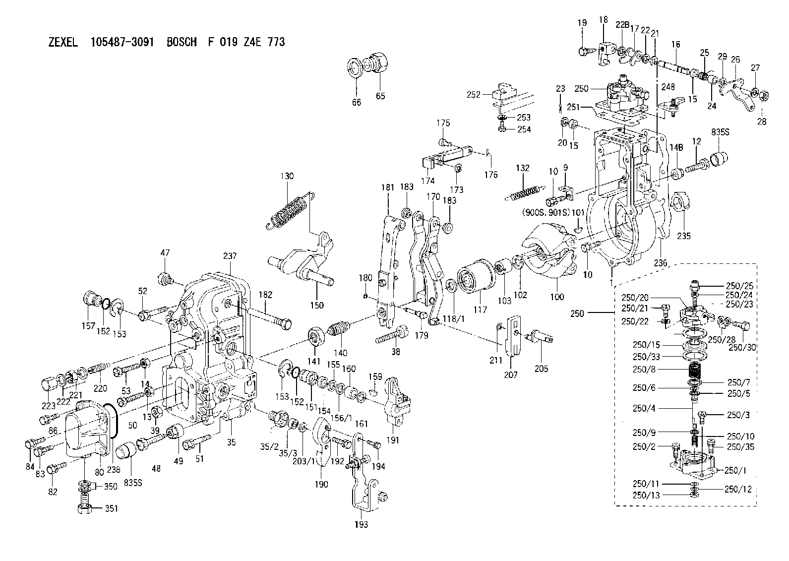
BOSCH
F 019 Z4E 773
f019z4e773
ZEXEL
105487-3091
1054873091
MITSUBISHI
ME726581
me726581
Rating:
Scheme ###:
| 1. | [1] | 154004-1720 | GOVERNOR HOUSING |
| 9. | [1] | 154350-6000 | PLATE |
| 10. | [8] | 020106-2040 | BLEEDER SCREW |
| 10. | [8] | 020106-2040 | BLEEDER SCREW |
| 12. | [1] | 154010-7300 | BLEEDER SCREW |
| 13. | [1] | 013020-6040 | UNION NUT |
| 14. | [1] | 013020-8040 | UNION NUT |
| 14B. | [1] | 154011-2300 | UNION NUT |
| 15. | [2] | 029620-8050 | PACKING RING |
| 15. | [2] | 029620-8050 | PACKING RING |
| 16. | [1] | 155004-3301 | LEVER SHAFT |
| 17. | [1] | 154408-1520 | CONTROL LEVER |
| 18. | [1] | 155003-1920 | CONTROL LEVER |
| 19. | [1] | 155006-0700 | BLEEDER SCREW |
| 20. | [1] | 139308-0900 | PLAIN WASHER D16&8T1 |
| 20B. | [1] | 139308-1000 | PLAIN WASHER D16&8T1.5 |
| 21. | [1] | 016010-0740 | LOCKING WASHER |
| 22. | [0] | 029310-8040 | SHIM D13.5&8T0.2 |
| 22. | [0] | 139408-1400 | SHIM D16&8T0.2 |
| 22B. | [0] | 029310-8050 | SHIM D13.5&8T0.5 |
| 23. | [1] | 025520-1210 | SPLIT PIN |
| 24. | [1] | 154206-2000 | BUSHING |
| 25. | [1] | 154327-5200 | COILED SPRING |
| 26. | [1] | 154365-2500 | CONTROL LEVER |
| 27. | [1] | 014110-8440 | LOCKING WASHER D15.4&8.2T2 |
| 28. | [1] | 013020-8040 | UNION NUT |
| 29. | [1] | 139408-1400 | SHIM D16&8T0.2 |
| 29B. | [0] | 139408-1400 | SHIM D16&8T0.2 |
| 29C. | [0] | 139408-1500 | SHIM D16&8T0.5 |
| 35. | [1] | 154513-9920 | GOVERNOR COVER |
| 35/2. | [1] | 154321-1800 | BUSHING |
| 35/3. | [1] | 029621-0080 | PACKING RING |
| 38. | [1] | 154031-3500 | FLAT-HEAD SCREW |
| 39. | [1] | 154011-1600 | UNION NUT |
| 47. | [1] | 154036-0300 | CAPSULE |
| 48. | [1] | 154010-7100 | BLEEDER SCREW |
| 49. | [1] | 154011-2200 | UNION NUT |
| 50. | [1] | 155615-1900 | BLEEDER SCREW |
| 51. | [4] | 020106-3840 | BLEEDER SCREW |
| 52. | [2] | 020106-5040 | BLEEDER SCREW |
| 53. | [1] | 154010-7300 | BLEEDER SCREW |
| 65. | [1] | 155404-1700 | CAP |
| 66. | [1] | 026524-3040 | GASKET |
| 80. | [1] | 154063-6021 | COVER |
| 82. | [1] | 029020-6210 | BLEEDER SCREW |
| 83. | [1] | 020006-1640 | BLEEDER SCREW |
| 84. | [1] | 029020-6210 | BLEEDER SCREW |
| 86. | [1] | 020006-1640 | BLEEDER SCREW |
| 100. | [1] | 154100-9620 | FLYWEIGHT ASSEMBLY |
| 101. | [1] | 025803-1310 | WOODRUFF KEY 13 MM |
| 102. | [1] | 029321-2020 | LOCKING WASHER |
| 103. | [1] | 029231-2030 | UNION NUT |
| 117. | [1] | 154123-2320 | SLIDING PIECE |
| 118/1. | [0] | 029311-0010 | SHIM D14&10.1T0.2 |
| 118/1. | [0] | 029311-0180 | SHIM D14&10.1T0.3 |
| 118/1. | [0] | 029311-0190 | SHIM D14&10.1T0.40 |
| 118/1. | [0] | 029311-0210 | SHIM D14&10.1T1 |
| 118/1. | [0] | 139410-0000 | SHIM D14&10.1T0.5 |
| 118/1. | [0] | 139410-0100 | SHIM D14&10.1T1.5 |
| 118/1. | [0] | 139410-3000 | SHIM D14&10.1T2.0 |
| 118/1. | [0] | 139410-3100 | SHIM D14&10.1T3.0 |
| 118/1. | [0] | 139410-3200 | SHIM D14&10.1T4.0 |
| 130. | [1] | 154150-6200 | GOVERNOR SPRING |
| 132. | [1] | 154154-0200 | COILED SPRING |
| 140. | [1] | 154178-2120 | HEADLESS SCREW |
| 141. | [1] | 029201-6010 | UNION NUT |
| 150. | [1] | 154200-3801 | SWIVELLING LEVER |
| 151. | [1] | 154204-2001 | BUSHING |
| 152. | [2] | 029631-8020 | O-RING |
| 152. | [2] | 029631-8020 | O-RING |
| 153. | [2] | 154354-3900 | LOCKING WASHER |
| 153. | [2] | 154354-3900 | LOCKING WASHER |
| 154. | [1] | 139611-0000 | PACKING RING |
| 155. | [1] | 139411-0000 | SHIM |
| 156/1. | [0] | 029311-1110 | SHIM D17&11T0.1 |
| 156/1. | [0] | 029311-1120 | SHIM D17&11T0.2 |
| 156/1. | [0] | 029311-1130 | SHIM D17&11T0.3 |
| 157. | [1] | 154204-3400 | BUSHING |
| 159. | [1] | 025803-1310 | WOODRUFF KEY 13 MM |
| 160. | [1] | 154206-0900 | BUSHING |
| 161. | [0] | 154206-0200 | PLAIN WASHER D19.5&11.2T1.0 |
| 170. | [1] | 154216-2520 | GUIDE LEVER |
| 173. | [1] | 016010-0540 | LOCKING WASHER |
| 174. | [1] | 154234-2920 | STRAP |
| 175. | [1] | 159231-4900 | BEARING PIN |
| 176. | [1] | 155402-3800 | SAFETY PIN |
| 179. | [1] | 154238-0301 | BEARING PIN |
| 180. | [1] | 016010-0540 | LOCKING WASHER |
| 181. | [1] | 154236-5300 | TENSIONING LEVER |
| 182. | [1] | 154237-0900 | BEARING PIN |
| 183. | [2] | 154237-0600 | BUSHING |
| 183. | [2] | 154237-0600 | BUSHING |
| 190. | [1] | 154360-2800 | CONTROL LEVER |
| 191. | [1] | 154340-0120 | CONTROL LEVER |
| 192. | [1] | 020006-1670 | BLEEDER SCREW |
| 193. | [1] | 154368-3120 | CONTROL LEVER |
| 194. | [2] | 020006-1240 | BLEEDER SCREW |
| 203/1. | [0] | 029311-0640 | SHIM D26.0&10.2T0.95 |
| 203/1. | [0] | 029311-0650 | SHIM D26.0&10.2T0.20 |
| 203/1. | [0] | 029311-0660 | SHIM D26.0&10.2T0.25 |
| 203/1. | [0] | 029311-0670 | SHIM D26.0&10.2T0.30 |
| 203/1. | [0] | 029311-0680 | SHIM D26.0&10.2T0.35 |
| 203/1. | [0] | 029311-0690 | SHIM D26.0&10.2T0.40 |
| 203/1. | [0] | 029311-0700 | SHIM D26.0&10.2T0.50 |
| 203/1. | [0] | 139410-1400 | SHIM D26&10.2T0.7 |
| 203/1. | [0] | 139410-1500 | SHIM D26&10.2T0.9 |
| 203/1. | [0] | 139410-1600 | SHIM D26&10.2T0.8 |
| 203/1. | [0] | 139410-2700 | SHIM D26&10.2T0.6 |
| 205. | [1] | 154324-3000 | LEVER SHAFT |
| 207. | [1] | 154326-0300 | CONTROL LEVER |
| 211. | [1] | 016010-0840 | LOCKING WASHER |
| 220. | [1] | 154050-6220 | HEADLESS SCREW |
| 221. | [1] | 029201-2130 | UNION NUT |
| 222. | [2] | 026512-1540 | GASKET |
| 223. | [1] | 154159-1200 | CAP NUT |
| 235. | [1] | 155412-5200 | IMPELLER WHEEL |
| 236. | [1] | 154371-5600 | GASKET |
| 237. | [1] | 154390-0300 | GASKET |
| 238. | [1] | 029635-2020 | O-RING |
| 248. | [1] | 154356-9320 | BRACKET |
| 250. | [1] | 154417-0321 | MANIFOLD-PRESSURE COMP. |
| 250. | [1] | 154417-0321 | MANIFOLD-PRESSURE COMP. |
| 250/1. | [1] | 154408-6220 | DIAPHRAGM HOUSING |
| 250/2. | [2] | 020106-1640 | BLEEDER SCREW |
| 250/3. | [1] | 029020-6260 | BLEEDER SCREW |
| 250/4. | [1] | 154400-5101 | STOP PIN |
| 250/5. | [1] | 153400-0900 | SLOTTED WASHER |
| 250/6. | [1] | 016010-0740 | LOCKING WASHER |
| 250/7. | [0] | 029312-0180 | SHIM D25.5&20T0.5 |
| 250/7B. | [0] | 029312-0210 | SHIM D25.5&20T0.2 |
| 250/8. | [1] | 154403-9500 | COILED SPRING |
| 250/9. | [0] | 154355-3900 | SHIM D18&12.5T0.10 |
| 250/9B. | [0] | 154355-4000 | SHIM D18&12.5T0.20 |
| 250/9C. | [0] | 154355-4100 | SHIM D18&12.5T0.30 |
| 250/10. | [1] | 154411-2200 | COILED SPRING |
| 250/11. | [1] | 153400-0800 | SPRING SEAT |
| 250/12. | [1] | 014110-5440 | LOCKING WASHER |
| 250/13. | [1] | 013030-5240 | UNION NUT |
| 250/15. | [1] | 154400-9320 | DIAPHRAGM |
| 250/20. | [1] | 154404-5100 | COVER |
| 250/21. | [3] | 029010-6310 | BLEEDER SCREW |
| 250/22. | [3] | 014110-6440 | LOCKING WASHER D12.2&6.1T1.5 |
| 250/23. | [1] | 154404-5300 | FLAT-HEAD SCREW |
| 250/24. | [1] | 023040-6040 | UNION NUT |
| 250/25. | [1] | 154406-7800 | CAP NUT |
| 250/28. | [2] | 026510-1340 | GASKET |
| 250/30. | [1] | 029731-0180 | EYE BOLT |
| 250/33. | [2] | 154413-2600 | GASKET |
| 250/35. | [1] | 020106-2040 | BLEEDER SCREW |
| 251. | [1] | 154390-2000 | GASKET |
| 252. | [1] | 154232-1220 | PLATE |
| 253. | [1] | 029320-5020 | LOCKING WASHER |
| 254. | [1] | 010535-1040 | FLAT-HEAD SCREW |
| 350. | [2] | 026512-1840 | GASKET |
| 351. | [1] | 153556-4800 | EYE BOLT |
| 835S. | [2] | 154062-1700 | CAP |
| 835S. | [2] | 154062-1700 | CAP |
| 900S. | [1] | 025803-1310 | WOODRUFF KEY 13 MM |
| 901S. | [1] | 025803-1610 | WOODRUFF KEY 16 MM |
Include in #1:
106651-2281
as GOVERNOR
Cross reference number
Zexel num
Bosch num
Firm num
Name
Information:
Start By:a. remove fuel injection linesb. remove fuel filter and basec. remove fuel transfer pump The following illustrations are of a 3304 Engine. 1. Disconnect the governor control linkage from the governor.2. On 3304 Engines only: remove oil supply line (1), oil drain line (2) and heat shield (3). Remove the O-ring seal from oil drain line (2) if it is damaged. Remove the gaskets and screen from the top of the turbocharger.3. Disconnect fuel drain lines (4) and (5) from the fuel injection pump housing and governor. 4. Remove the nuts, washers and cover from the timing gear housing. Remove studs (6) if they are damaged or loose.5. Loosen bolt (7) enough to leave a gap of 3.18 mm (.125 in) between washer (8) and the fuel pump drive gear.6. Install Tool (A) as shown. Tighten the stud to pull the fuel pump drive gear loose from the taper on the fuel injection pump camshaft.7. Remove Tool (A), bolt (7) and washer (8) from the engine. 8. Fasten a nylon strap and hoist to the fuel injection pump housing and governor. The 3304 fuel injection pump housing and governor weighs 24 kg (53 lb). The 3306 fuel injection pump housing and governor weighs 29 kg (64 lb).9. Remove bolt (9), bolt (10), three nuts (11) and the fuel injection pump housing and governor. Remove the two O-ring seals from the bottom and the two O-ring seals from the front of the fuel injection pump housing and governor.Install Fuel Injection Pump Housing & Governor
The following illustrations are of a 3304 Engine. 1. Put clean engine oil on the O-ring seals. Install O-ring seals (1) in the bottom and O-ring seals (2) in the front of the fuel injection pump housing and governor. 2. Make sure O-ring seals (1) and (2) stay in position in the fuel injection pump housing and governor. Fasten a hoist to the fuel injection pump housing and governor, and put it in position on the engine. Install the two bolts at location (5) and the three nuts on studs (3) to hold the fuel injection pump housing and governor in position.3. Remove the bolts that hold cover (4) in position. Remove cover (4) and the gasket. 4. Put Tool (A) in position as shown. Install the bolt that holds the fuel pump drive gear to the fuel injection pump camshaft without the washer. This will allow the camshaft in the fuel system to be turned.5. Put pressure on the end of Tool (A) and turn the camshaft slowly until the Tool drops into the groove (slot) in the camshaft. Leave Tool (A) in position in the groove (slot). Remove the bolt from the end of the camshaft. 6. Install washer (6) with the large diameter toward the front of the engine. Install bolt (7) and tighten it to a torque of 6.8 N m (60 lb in).7. Install Tool (B) as shown in the flywheel housing. Make sure bolt (7) does not loosen as
The following illustrations are of a 3304 Engine. 1. Put clean engine oil on the O-ring seals. Install O-ring seals (1) in the bottom and O-ring seals (2) in the front of the fuel injection pump housing and governor. 2. Make sure O-ring seals (1) and (2) stay in position in the fuel injection pump housing and governor. Fasten a hoist to the fuel injection pump housing and governor, and put it in position on the engine. Install the two bolts at location (5) and the three nuts on studs (3) to hold the fuel injection pump housing and governor in position.3. Remove the bolts that hold cover (4) in position. Remove cover (4) and the gasket. 4. Put Tool (A) in position as shown. Install the bolt that holds the fuel pump drive gear to the fuel injection pump camshaft without the washer. This will allow the camshaft in the fuel system to be turned.5. Put pressure on the end of Tool (A) and turn the camshaft slowly until the Tool drops into the groove (slot) in the camshaft. Leave Tool (A) in position in the groove (slot). Remove the bolt from the end of the camshaft. 6. Install washer (6) with the large diameter toward the front of the engine. Install bolt (7) and tighten it to a torque of 6.8 N m (60 lb in).7. Install Tool (B) as shown in the flywheel housing. Make sure bolt (7) does not loosen as