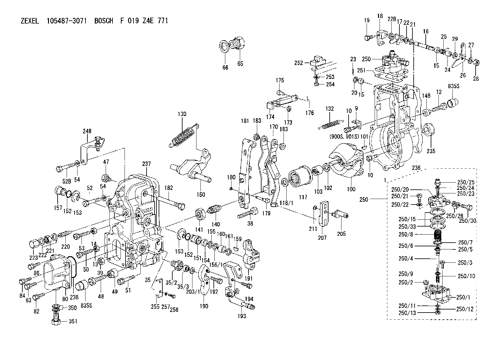
Information governor
BOSCH
F 019 Z4E 771
f019z4e771
ZEXEL
105487-3071
1054873071
MITSUBISHI
ME726580
me726580
Rating:
Scheme ###:
| 1. | [1] | 154004-1720 | GOVERNOR HOUSING |
| 9. | [1] | 154350-6000 | PLATE |
| 10. | [8] | 020106-2040 | BLEEDER SCREW M6P1L20 |
| 10. | [8] | 020106-2040 | BLEEDER SCREW M6P1L20 |
| 12. | [1] | 154010-7300 | BLEEDER SCREW M8P1.25L60 |
| 13. | [1] | 013020-6040 | UNION NUT M6P1H5 |
| 14. | [1] | 013020-8040 | UNION NUT M8P1.25H7 |
| 14B. | [1] | 154011-2300 | UNION NUT |
| 15. | [2] | 029620-8050 | PACKING RING |
| 15. | [2] | 029620-8050 | PACKING RING |
| 16. | [1] | 155004-3301 | LEVER SHAFT |
| 17. | [1] | 154408-1520 | CONTROL LEVER |
| 18. | [1] | 155003-1920 | CONTROL LEVER |
| 19. | [1] | 155006-0700 | BLEEDER SCREW |
| 20. | [1] | 139308-0900 | PLAIN WASHER D16&8T1 |
| 20B. | [1] | 139308-1000 | PLAIN WASHER D16&8T1.5 |
| 21. | [1] | 016010-0740 | LOCKING WASHER |
| 22. | [0] | 029310-8040 | SHIM D13.5&8T0.2 |
| 22. | [7] | 139408-1400 | SHIM |
| 22B. | [0] | 029310-8050 | SHIM D13.5&8T0.5 |
| 22B. | [7] | 139408-1500 | SHIM |
| 23. | [1] | 025520-1210 | SPLIT PIN |
| 24. | [1] | 154206-2000 | BUSHING |
| 25. | [1] | 154327-5200 | COILED SPRING |
| 26. | [1] | 154366-5800 | CONTROL LEVER |
| 27. | [1] | 014110-8440 | LOCKING WASHER |
| 28. | [1] | 013020-8040 | UNION NUT M8P1.25H7 |
| 29. | [1] | 139408-1400 | SHIM |
| 29B. | [0] | 139408-1400 | SHIM |
| 29C. | [0] | 139408-1500 | SHIM |
| 35. | [1] | 154513-9920 | GOVERNOR COVER |
| 35/2. | [1] | 154321-1800 | BUSHING |
| 35/3. | [1] | 029621-0080 | PACKING RING |
| 38. | [1] | 154031-3500 | FLAT-HEAD SCREW |
| 39. | [1] | 154011-1600 | UNION NUT |
| 47. | [1] | 154036-0300 | CAPSULE |
| 48. | [1] | 154010-7100 | BLEEDER SCREW M10P1.25L47 |
| 48B. | [1] | 154010-8200 | BLEEDER SCREW |
| 49. | [1] | 154011-2200 | UNION NUT |
| 50. | [1] | 155615-1900 | BLEEDER SCREW |
| 51. | [4] | 020106-3840 | BLEEDER SCREW |
| 52. | [1] | 010006-5040 | BLEEDER SCREW M6P1L50 |
| 52B. | [1] | 010006-5540 | BLEEDER SCREW M6P1L55 4T |
| 53. | [1] | 154010-7300 | BLEEDER SCREW M8P1.25L60 |
| 54. | [2] | 014110-6440 | LOCKING WASHER |
| 54. | [2] | 014110-6440 | LOCKING WASHER |
| 65. | [1] | 155404-1700 | CAP |
| 66. | [1] | 026524-3040 | GASKET |
| 80. | [1] | 154063-6021 | COVER |
| 82. | [1] | 029020-6210 | BLEEDER SCREW |
| 83. | [1] | 020006-1640 | BLEEDER SCREW M6P1L16 4T |
| 84. | [1] | 029020-6210 | BLEEDER SCREW |
| 86. | [1] | 020006-1640 | BLEEDER SCREW M6P1L16 4T |
| 100. | [1] | 154100-9620 | FLYWEIGHT ASSEMBLY |
| 101. | [1] | 025803-1310 | WOODRUFF KEY |
| 102. | [1] | 029321-2020 | LOCKING WASHER |
| 103. | [1] | 029231-2030 | UNION NUT |
| 117. | [1] | 154123-2320 | SLIDING PIECE |
| 118/1. | [0] | 029311-0010 | SHIM D14&10.1T0.2 |
| 118/1. | [0] | 029311-0180 | SHIM D14&10.1T0.3 |
| 118/1. | [0] | 029311-0190 | SHIM D14&10.1T0.40 |
| 118/1. | [0] | 029311-0210 | SHIM D14&10.1T1 |
| 118/1. | [0] | 139410-0000 | SHIM D14.0&10.1T0.5 |
| 118/1. | [0] | 139410-0100 | SHIM D14.0&10.1T1.5 |
| 118/1. | [0] | 139410-3000 | SHIM D14&10.1T2.0 |
| 118/1. | [0] | 139410-3100 | SHIM D14&10.1T3.0 |
| 118/1. | [0] | 139410-3200 | SHIM D14&10.1T4.0 |
| 130. | [1] | 154150-6200 | GOVERNOR SPRING |
| 132. | [1] | 154154-0200 | COILED SPRING |
| 140. | [1] | 154178-2120 | HEADLESS SCREW |
| 141. | [1] | 029201-6010 | UNION NUT |
| 150. | [1] | 154200-3801 | SWIVELLING LEVER |
| 151. | [1] | 154204-2001 | BUSHING |
| 152. | [2] | 029631-8020 | O-RING |
| 152. | [2] | 029631-8020 | O-RING |
| 153. | [2] | 154354-3900 | LOCKING WASHER |
| 153. | [2] | 154354-3900 | LOCKING WASHER |
| 154. | [1] | 139611-0000 | PACKING RING |
| 155. | [1] | 139411-0000 | SHIM |
| 156/1. | [0] | 029311-1110 | SHIM D17&11T0.1 |
| 156/1. | [0] | 029311-1120 | SHIM D17&11T0.2 |
| 156/1. | [0] | 029311-1130 | SHIM D17&11T0.3 |
| 157. | [1] | 154204-3400 | BUSHING |
| 159. | [1] | 025803-1310 | WOODRUFF KEY |
| 160. | [1] | 154206-0900 | BUSHING |
| 161. | [0] | 154206-0200 | PLAIN WASHER D19.5&11.2T1.0 |
| 170. | [1] | 154216-2520 | GUIDE LEVER |
| 173. | [1] | 016010-0540 | LOCKING WASHER |
| 174. | [1] | 154234-2920 | STRAP |
| 175. | [1] | 159231-4900 | BEARING PIN |
| 176. | [1] | 155402-3800 | SAFETY PIN |
| 179. | [1] | 154238-0301 | BEARING PIN |
| 180. | [1] | 016010-0540 | LOCKING WASHER |
| 181. | [1] | 154236-5300 | TENSIONING LEVER |
| 182. | [1] | 154237-0900 | BEARING PIN |
| 183. | [2] | 154237-0600 | BUSHING |
| 183. | [2] | 154237-0600 | BUSHING |
| 190. | [1] | 154360-2800 | CONTROL LEVER |
| 191. | [1] | 154340-0120 | CONTROL LEVER |
| 192. | [1] | 020006-1670 | BLEEDER SCREW M6P1L16 7T |
| 193. | [1] | 154368-3820 | CONTROL LEVER |
| 194. | [2] | 020006-1240 | BLEEDER SCREW M6P1L12 4T |
| 203/1. | [0] | 029311-0640 | SHIM D26.0&10.2T0.95 |
| 203/1. | [0] | 029311-0650 | SHIM D26.0&10.2T0.20 |
| 203/1. | [0] | 029311-0660 | SHIM D26.0&10.2T0.25 |
| 203/1. | [0] | 029311-0670 | SHIM D26.0&10.2T0.30 |
| 203/1. | [0] | 029311-0680 | SHIM D26.0&10.2T0.35 |
| 203/1. | [0] | 029311-0690 | SHIM D26.0&10.2T0.40 |
| 203/1. | [0] | 029311-0700 | SHIM D26.0&10.2T0.50 |
| 203/1. | [0] | 139410-1400 | SHIM D26&10.2T0.7 |
| 203/1. | [0] | 139410-1500 | SHIM D26&10.2T0.9 |
| 203/1. | [0] | 139410-1600 | SHIM D26&10.2T0.8 |
| 203/1. | [0] | 139410-2700 | SHIM D26&10.2T0.6 |
| 205. | [1] | 154324-3000 | LEVER SHAFT |
| 207. | [1] | 154326-0300 | CONTROL LEVER |
| 211. | [1] | 016010-0840 | LOCKING WASHER |
| 220. | [1] | 154050-6220 | HEADLESS SCREW |
| 221. | [1] | 029201-2130 | UNION NUT M12P1.0H6 |
| 222. | [2] | 026512-1540 | GASKET D15.4&12.2T1.50 |
| 223. | [1] | 154159-1200 | CAP NUT |
| 235. | [1] | 155412-5200 | IMPELLER WHEEL |
| 236. | [1] | 154371-5600 | GASKET |
| 237. | [1] | 154390-0300 | GASKET |
| 238. | [1] | 029635-2020 | O-RING |
| 248. | [1] | 154359-3920 | BRACKET |
| 250. | [1] | 154418-0421 | MANIFOLD-PRESSURE COMP. |
| 250. | [1] | 154418-0421 | MANIFOLD-PRESSURE COMP. |
| 250/1. | [1] | 154408-6220 | DIAPHRAGM HOUSING |
| 250/2. | [3] | 020106-1640 | BLEEDER SCREW M6P1.0L14 |
| 250/3. | [1] | 029020-6260 | BLEEDER SCREW |
| 250/4. | [1] | 154400-5101 | STOP PIN |
| 250/5. | [1] | 153400-0900 | SLOTTED WASHER |
| 250/6. | [1] | 016010-0740 | LOCKING WASHER |
| 250/7. | [0] | 029312-0180 | SHIM D25.5&20T0.5 |
| 250/7B. | [0] | 029312-0210 | SHIM D25.5&20T0.2 |
| 250/8. | [1] | 154403-4100 | COILED SPRING |
| 250/9. | [0] | 154355-3900 | SHIM D18&12.5T0.10 |
| 250/9B. | [0] | 154355-4000 | SHIM D18&12.5T0.20 |
| 250/9C. | [0] | 154355-4100 | SHIM D18&12.5T0.30 |
| 250/10. | [1] | 154411-2200 | COILED SPRING |
| 250/11. | [1] | 153400-0800 | SPRING SEAT |
| 250/12. | [1] | 014110-5440 | LOCKING WASHER |
| 250/13. | [1] | 013030-5240 | UNION NUT M5P0.8H3.2 |
| 250/15. | [1] | 154400-9320 | DIAPHRAGM |
| 250/20. | [1] | 154404-5100 | COVER |
| 250/21. | [3] | 029010-6310 | BLEEDER SCREW |
| 250/22. | [3] | 014110-6440 | LOCKING WASHER |
| 250/23. | [1] | 154404-5300 | FLAT-HEAD SCREW |
| 250/24. | [1] | 023040-6040 | UNION NUT |
| 250/25. | [1] | 154406-7800 | CAP NUT |
| 250/28. | [2] | 026510-1340 | GASKET D13.4&10.2T1 |
| 250/30. | [1] | 029731-0180 | EYE BOLT |
| 250/33. | [2] | 154413-2600 | GASKET |
| 251. | [1] | 154390-2000 | GASKET |
| 252. | [1] | 154232-1220 | PLATE |
| 253. | [1] | 029320-5020 | LOCKING WASHER |
| 254. | [1] | 010535-1040 | FLAT-HEAD SCREW M5P0.8L10 |
| 255. | [1] | 154359-4000 | BRACKET |
| 256. | [2] | 139016-0100 | BLEEDER SCREW |
| 257. | [2] | 014111-6440 | LOCKING WASHER |
| 350. | [2] | 026512-1840 | GASKET D17.9&12.2T1.50 |
| 351. | [1] | 153556-4800 | EYE BOLT |
| 835S. | [2] | 154062-1700 | CAP D20L32 |
| 835S. | [2] | 154062-1700 | CAP D20L32 |
| 900S. | [1] | 025803-1310 | WOODRUFF KEY |
| 901S. | [1] | 025803-1610 | WOODRUFF KEY |
Cross reference number
Zexel num
Bosch num
Firm num
Name
Information:
Start By:a. remove timing gear coverb. remove flywheel housing*c. remove engine oil cooler**d. remove oil filter base***Put the engine in time before the flywheel housing is removed. See the topic, "Finding Top Center Compression Position For No. 1 Piston" in Testing & Adjusting Manual SENR6471.**These operations must be done to install Tool (A) on the engine.
Typical Example1. Fasten the engine on Tool (A). The weight of the engine is 1362 kg (3000 lb).2. Remove the bolts and nuts that hold air cleaner group (1), pipe assembly (3), bracket assembly (4) and lifting plate (5) as a unit to the engine. Fasten a hoist to the unit and remove it from the engine. The weight of the unit is approximately 39 kg (85 lb).3. Remove tube assembly (2) from the engine.
Typical Example4. Install the two bolts to hold the primary fuel filter bracket (6) in place while the engine is turned with Tool (A). 5. Turn the engine to the position shown with Tool (A). Remove rod bearing caps (8) from the ends of the connecting rods. Push the connecting rods away from the crankshaft.6. Remove the bolts and remove main bearing caps (7) from the crankshaft. 7. Remove thrust plates (9) from the center main bearing journal. 8. Fasten a hoist to crankshaft (10) with tooling (B). Remove crankshaft (10) from the engine block. The weight of the crankshaft is 159 kg (350 lb). 9. Use Tool (C) to remove outer gear (2) from the end of the crankshaft.10. Use a hammer and chisel to remove the spacer from the crankshaft. 11. Use Tool (D) to remove the gear alignment dowel from the crankshaft.12. Use Tool (C) to remove inner gear (11) from the end of the crankshaft. If new main bearings are not to be installed, put identification on the old main bearings as to their location in the cylinder block and to which main bearings caps they belong.13. Remove main bearings (13) from the cylinder block and the main bearing caps.Install Crankshaft
1. If the dowel was removed from the flywheel end of the crankshaft, install it in the crankshaft to a maximum dimension of 6.4 mm (.25 in).2. Heat the crankshaft gears to a maximum temperature of 205° C (400° F).3. The centerline of inner gear key must be in alignment with the centerline of the dowel hole within 0.51 mm (.020 in). Install crankshaft inner gear (14) on the crankshaft.4. Install the spacer on the crankshaft.5. Install the dowel in the crankshaft. The dowel must be extended no more than 4.1 0.5 mm (.16 .02 in) from the surface of the crankshaft. The dowel in the crankshaft must be in alignment with the notch in crankshaft gear (15).6. Make sure the "V" mark on the crankshaft gear is toward the outside, and install crankshaft gear (15). 7. Thoroughly clean the cylinder block and main bearing caps.
Make sure the upper and lower halves of the main bearings are installed so the bearing tabs fit