Information governor
BOSCH
F 019 Z4E 768
f019z4e768
ZEXEL
105487-3020
1054873020
MITSUBISHI
ME722769
me722769
Rating:
Scheme ###:
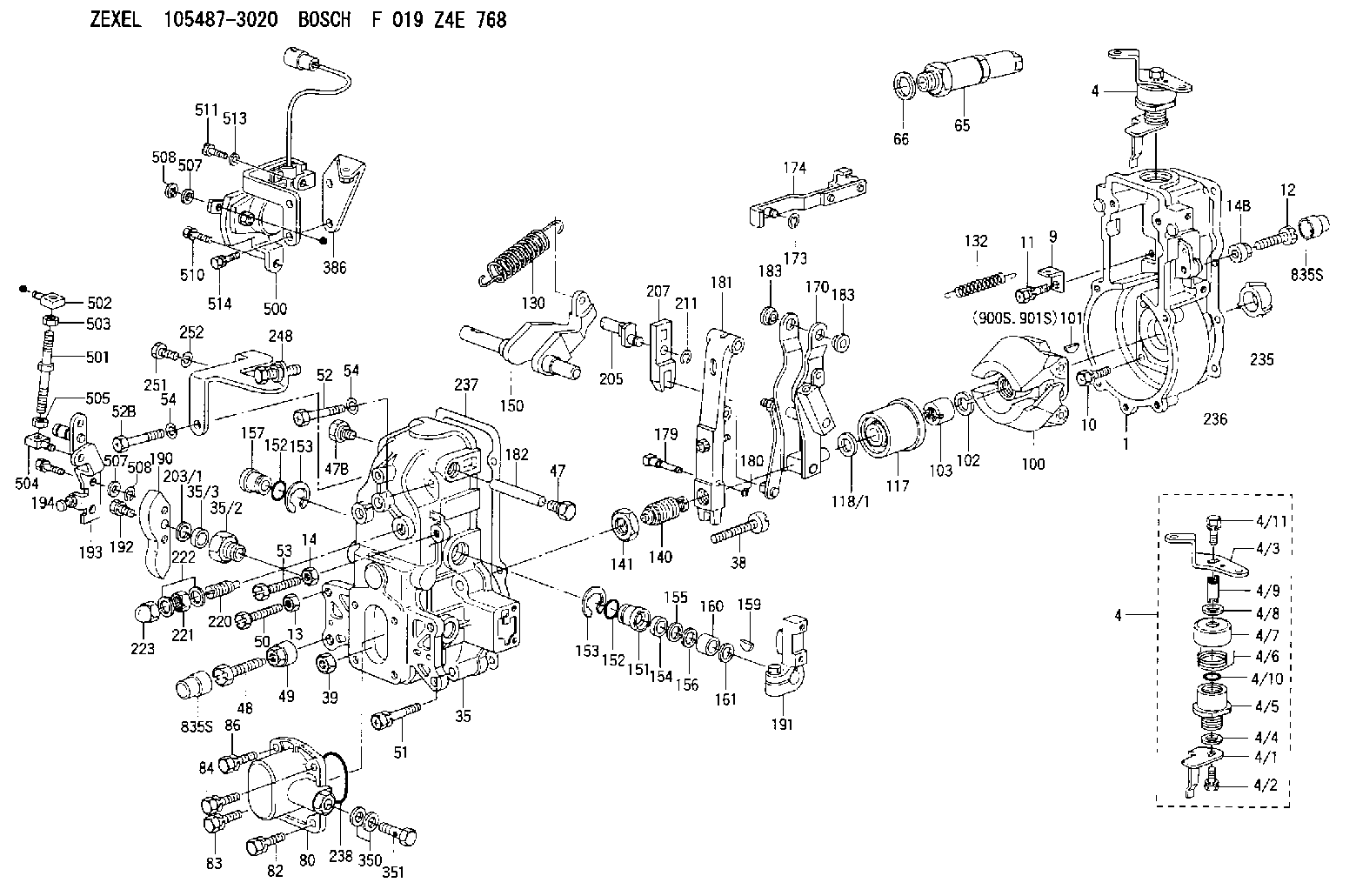
| 1. | [1] | 154004-0100 | GOVERNOR HOUSING |
| 4. | [1] | 154365-2220 | CONTROL LEVER |
| 4. | [1] | 154365-2220 | CONTROL LEVER |
| 4/1. | [1] | 154304-6200 | CONTROL LEVER |
| 4/2. | [1] | 154352-2000 | BLEEDER SCREW |
| 4/3. | [1] | 154365-2200 | CONTROL LEVER |
| 4/4. | [1] | 029311-0230 | SHIM D18&10.3T0.5 |
| 4/5. | [1] | 154321-1500 | BUSHING |
| 4/6. | [1] | 154327-6701 | COILED SPRING |
| 4/7. | [1] | 154322-0100 | CAP |
| 4/8. | [1] | 029311-0220 | SHIM D18&10.3T0.2 |
| 4/9. | [1] | 154324-2700 | LEVER SHAFT |
| 4/10. | [1] | 029631-0030 | O-RING &9.8W2.3 |
| 4/11. | [1] | 020006-1240 | BLEEDER SCREW M6P1L12 4T |
| 9. | [1] | 154350-6000 | PLATE |
| 10. | [4] | 020106-2040 | BLEEDER SCREW M6P1L20 |
| 11. | [4] | 020106-1840 | BLEEDER SCREW M6P1L18 |
| 12. | [1] | 154010-7400 | BLEEDER SCREW M8P1.25L55 |
| 13. | [1] | 013020-6040 | UNION NUT M6P1H5 |
| 14. | [1] | 013020-8040 | UNION NUT M8P1.25H7 |
| 14B. | [1] | 154011-2300 | UNION NUT |
| 35. | [1] | 154514-0320 | GOVERNOR COVER |
| 35/2. | [1] | 154321-2000 | BUSHING |
| 35/3. | [1] | 029621-0080 | PACKING RING |
| 38. | [1] | 154031-3401 | FLAT-HEAD SCREW |
| 39. | [1] | 029201-0160 | UNION NUT |
| 47. | [1] | 154036-1900 | CAPSULE |
| 47B. | [1] | 154036-1800 | CAPSULE |
| 48. | [1] | 154010-6000 | BLEEDER SCREW M10P1.25L55 |
| 48B. | [1] | 154010-7700 | BLEEDER SCREW M10P1.25L51 |
| 49. | [1] | 154011-2200 | UNION NUT |
| 50. | [1] | 155615-1900 | BLEEDER SCREW |
| 51. | [5] | 020106-4540 | BLEEDER SCREW M6P1.0L45 |
| 52. | [1] | 010006-6040 | BLEEDER SCREW |
| 52B. | [1] | 029010-6850 | BLEEDER SCREW |
| 53. | [1] | 154010-7300 | BLEEDER SCREW M8P1.25L60 |
| 54. | [2] | 014110-6440 | LOCKING WASHER |
| 54. | [2] | 014110-6440 | LOCKING WASHER |
| 65. | [1] | 153020-4320 | STOPPING DEVICE |
| 66. | [1] | 026524-3040 | GASKET |
| 80. | [1] | 154063-6521 | COVER |
| 82. | [1] | 020006-1640 | BLEEDER SCREW M6P1L16 4T |
| 83. | [1] | 029020-6210 | BLEEDER SCREW |
| 84. | [1] | 020006-1640 | BLEEDER SCREW M6P1L16 4T |
| 86. | [1] | 029020-6210 | BLEEDER SCREW |
| 100. | [1] | 154100-9220 | FLYWEIGHT ASSEMBLY |
| 101. | [1] | 025803-1310 | WOODRUFF KEY |
| 102. | [1] | 029321-2020 | LOCKING WASHER |
| 103. | [1] | 139212-0000 | UNION NUT |
| 117. | [1] | 154123-2320 | SLIDING PIECE |
| 118/1. | [0] | 029311-0010 | SHIM D14&10.1T0.2 |
| 118/1. | [0] | 029311-0180 | SHIM D14&10.1T0.3 |
| 118/1. | [0] | 029311-0190 | SHIM D14&10.1T0.40 |
| 118/1. | [0] | 029311-0210 | SHIM D14&10.1T1 |
| 118/1. | [0] | 139410-0000 | SHIM D14.0&10.1T0.5 |
| 118/1. | [0] | 139410-0100 | SHIM D14.0&10.1T1.5 |
| 118/1. | [0] | 139410-3000 | SHIM D14&10.1T2.0 |
| 118/1. | [0] | 139410-3100 | SHIM D14&10.1T3.0 |
| 118/1. | [0] | 139410-3200 | SHIM D14&10.1T4.0 |
| 130. | [1] | 154150-8300 | GOVERNOR SPRING |
| 132. | [1] | 154154-0200 | COILED SPRING |
| 140. | [1] | 154183-0420 | HEADLESS SCREW |
| 141. | [1] | 139218-0100 | UNION NUT |
| 150. | [1] | 154200-5401 | SWIVELLING LEVER |
| 151. | [1] | 154200-5501 | BUSHING |
| 152. | [2] | 139700-0000 | O-RING |
| 152. | [2] | 139700-0000 | O-RING |
| 153. | [2] | 154354-3900 | LOCKING WASHER |
| 153. | [2] | 154354-3900 | LOCKING WASHER |
| 154. | [1] | 139610-0101 | PACKING RING |
| 155. | [1] | 139411-0100 | SHIM D22.0&12.0T0.40 |
| 156. | [0] | 139411-0200 | SHIM D18.0&12.0T0.10 |
| 156B. | [0] | 139411-0300 | SHIM D18.0&12.0T0.20 |
| 156C. | [0] | 139411-0400 | SHIM D18.0&12.0T0.30 |
| 157. | [1] | 154204-3500 | BUSHING |
| 159. | [1] | 025803-1310 | WOODRUFF KEY |
| 160. | [1] | 154206-2300 | BUSHING |
| 161. | [0] | 154206-2400 | PLAIN WASHER D20.5&12.2T1 |
| 170. | [1] | 154216-1820 | FORK LEVER |
| 173. | [1] | 016010-0540 | LOCKING WASHER |
| 174. | [1] | 154230-6620 | STRAP |
| 179. | [1] | 154238-0201 | BEARING PIN |
| 180. | [1] | 016010-0540 | LOCKING WASHER |
| 181. | [1] | 154236-5200 | TENSIONING LEVER |
| 182. | [1] | 154237-1200 | BEARING PIN |
| 183. | [2] | 154237-1300 | BUSHING |
| 183. | [2] | 154237-1300 | BUSHING |
| 190. | [1] | 154360-2700 | CONTROL LEVER |
| 191. | [1] | 154340-1920 | CONTROL LEVER |
| 192. | [1] | 020006-1670 | BLEEDER SCREW M6P1L16 7T |
| 193. | [1] | 154368-4820 | CONTROL LEVER |
| 194. | [2] | 020006-1240 | BLEEDER SCREW M6P1L12 4T |
| 203/1. | [0] | 029311-0640 | SHIM D26.0&10.2T0.95 |
| 203/1. | [0] | 029311-0650 | SHIM D26.0&10.2T0.20 |
| 203/1. | [0] | 029311-0660 | SHIM D26.0&10.2T0.25 |
| 203/1. | [0] | 029311-0670 | SHIM D26.0&10.2T0.30 |
| 203/1. | [0] | 029311-0680 | SHIM D26.0&10.2T0.35 |
| 203/1. | [0] | 029311-0690 | SHIM D26.0&10.2T0.40 |
| 203/1. | [0] | 029311-0700 | SHIM D26.0&10.2T0.50 |
| 203/1. | [0] | 139410-1400 | SHIM D26&10.2T0.7 |
| 203/1. | [0] | 139410-1500 | SHIM D26&10.2T0.9 |
| 203/1. | [0] | 139410-1600 | SHIM D26&10.2T0.8 |
| 203/1. | [0] | 139410-2700 | SHIM D26&10.2T0.6 |
| 205. | [1] | 154324-3400 | LEVER SHAFT |
| 207. | [1] | 154326-0300 | CONTROL LEVER |
| 211. | [1] | 016010-0840 | LOCKING WASHER |
| 220. | [1] | 154050-6220 | HEADLESS SCREW |
| 221. | [1] | 029201-2140 | UNION NUT |
| 222. | [2] | 026512-1540 | GASKET D15.4&12.2T1.50 |
| 223. | [1] | 154159-0100 | CAP NUT |
| 235. | [1] | 155412-5200 | IMPELLER WHEEL |
| 236. | [1] | 154371-5600 | GASKET |
| 237. | [1] | 154390-0200 | GASKET |
| 238. | [1] | 139700-0100 | O-RING |
| 248. | [1] | 154357-9720 | BRACKET |
| 251. | [1] | 010065-1240 | BLEEDER SCREW M5P0.8L12 |
| 252. | [1] | 014110-5440 | LOCKING WASHER |
| 350. | [2] | 026512-1840 | GASKET D17.9&12.2T1.50 |
| 351. | [1] | 153556-4800 | EYE BOLT |
| 386. | [1] | 154367-1420 | BRACKET |
| 500. | [1] | 154600-6220 | LOAD SENSOR ASSY |
| 501. | [1] | 154604-1600 | LEVER SHAFT |
| 502. | [1] | 154604-1700 | BEARING PIN |
| 503. | [1] | 013020-5240 | UNION NUT M5P0.8H4 |
| 504. | [1] | 154604-1800 | BEARING PIN |
| 505. | [1] | 029200-5130 | UNION NUT |
| 507. | [4] | 029310-5280 | SHIM D10.5&5T0.5 |
| 507. | [4] | 029310-5280 | SHIM D10.5&5T0.5 |
| 508. | [2] | 016010-0540 | LOCKING WASHER |
| 508. | [2] | 016010-0540 | LOCKING WASHER |
| 510. | [1] | 029010-6330 | BLEEDER SCREW M6P1.0L13 |
| 511. | [1] | 020106-1240 | BLEEDER SCREW M6P1.0L12 |
| 513. | [1] | 014010-6140 | PLAIN WASHER D13&6.5T1 |
| 514. | [2] | 020018-1640 | BLEEDER SCREW M8P1.25L16 4T |
| 835S. | [2] | 154062-1700 | CAP D20L32 |
| 835S. | [2] | 154062-1700 | CAP D20L32 |
| 900S. | [1] | 025803-1310 | WOODRUFF KEY |
| 901S. | [1] | 025803-1610 | WOODRUFF KEY |
Cross reference number
Zexel num
Bosch num
Firm num
Name
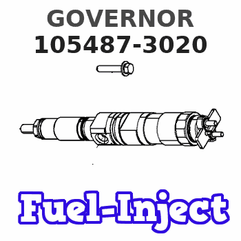
105487-3020
ME722769 MITSUBISHI
GOVERNOR
K 14JN MECHANICAL GOVERNOR GOV RFD GOV
K 14JN MECHANICAL GOVERNOR GOV RFD GOV
Information:
1. Disconnect fuel line (3) from the fuel transfer pump. Cap or plug immediately.2. Disconnect fuel line (4) from the fuel transfer pump. Cap or plug immediately.3. Remove bolts (1).4. Remove fuel transfer pump (2). Check the condition of the O-ring seal on the fuel transfer pump. If necessary, make a replacement. Put clean engine oil on the O-ring seal when assembling fuel transfer pump. For installation of the fuel transfer pump, reverse the removal steps.Disassemble & Assemble Fuel Transfer Pump
Start By:a. remove fuel transfer pump 1. Remove seal (1) from the fuel transfer pump.
Cover (2) is under spring tension. Remove the bolts that hold cover (2) slowly to prevent injury.
2. Remove bolts (3) and cover (2) the housing. 3. Remove seals (4) and valve (5) from cover (2). 4. Remove spring (6) from the piston.
Mark the orientation of valve (8) as to its location in the housing.
5. Remove washer (7) and valve (8) from the housing. 6. Remove piston (9) and sleeve (10) from the housing. 7. Remove seal (11) from sleeve (12). 8. Remove guide and tappet assembly (13) from the housing. 9. Remove seal (14) from guide (15).
If tappet (17) or guide (15) are damaged or worn, they must be replaced as a unit.
10. Remove ring (16) from tappet (17) and the tappet from guide (15). 11. Remove the bolts and cover (18) from the housing. 12. Remove seal (19) from cover (18). 13. Remove valve (20) from the housing. The following steps are for the assembly of the fuel transfer pump.14. Install valve (20) in the housing. Put clean fuel on seal (19) and install it on cover (18). Install the cover on the housing.15. Install tappet (17) in guide (15). Install ring (16) on tappet (17) to hold the tappet in the guide.16. Put clean fuel on seal (14) and install it on the guide and tappet assembly (13). Install guide and tappet assembly (13) in the housing.17. Put clean fuel on seal (11) and install it on sleeve (12). Install sleeve (12) in the housing.18. Install piston (9) in the housing. Install valve (8) and washer (7) in the housing. Install spring (6) in the piston.19. Install valve (5) in cover (2).20. Put clean fuel on seals (4) and put them in position on cover (2). Install cover (2) on the housing.21. Put seal (1) in position on the fuel transfer pump.End By:a. install fuel transfer pump