Information governor
BOSCH
9 420 613 165
9420613165
ZEXEL
105487-2204
1054872204
Rating:
Scheme ###:
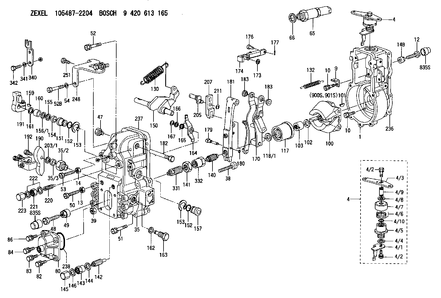
| 1. | [1] | 154000-4700 | GOVERNOR HOUSING |
| 4. | [1] | 154365-3120 | CONTROL LEVER |
| 4. | [1] | 154365-3120 | CONTROL LEVER |
| 4/1. | [1] | 154304-6200 | CONTROL LEVER |
| 4/2. | [2] | 154352-2000 | BLEEDER SCREW |
| 4/2. | [2] | 154352-2000 | BLEEDER SCREW |
| 4/3. | [1] | 154304-0900 | CONTROL LEVER |
| 4/4. | [1] | 029311-0230 | SHIM D18&10.3T0.5 |
| 4/5. | [1] | 154321-1500 | BUSHING |
| 4/6. | [1] | 154327-2901 | COILED SPRING |
| 4/7. | [1] | 154322-0100 | CAP |
| 4/8. | [1] | 029311-0220 | SHIM D18&10.3T0.2 |
| 4/9. | [1] | 154324-2700 | LEVER SHAFT |
| 4/10. | [1] | 029631-0030 | O-RING &9.8W2.3 |
| 9. | [1] | 154350-6000 | PLATE |
| 10. | [8] | 020106-2040 | BLEEDER SCREW M6P1L20 |
| 10. | [8] | 020106-2040 | BLEEDER SCREW M6P1L20 |
| 12. | [1] | 154010-7300 | BLEEDER SCREW M8P1.25L60 |
| 12B. | [1] | 154010-7400 | BLEEDER SCREW M8P1.25L55 |
| 13. | [1] | 013020-6040 | UNION NUT M6P1H5 |
| 14. | [1] | 154011-0100 | HEXAGON NUT |
| 14B. | [1] | 154011-2300 | UNION NUT |
| 35. | [1] | 154514-3920 | GOVERNOR COVER |
| 35/2. | [1] | 154321-2300 | BUSHING |
| 35/3. | [1] | 029621-0080 | PACKING RING |
| 38. | [1] | 154031-3500 | FLAT-HEAD SCREW |
| 39. | [1] | 154011-1600 | UNION NUT |
| 47. | [1] | 154036-1200 | CAPSULE |
| 48. | [1] | 154013-0301 | BLEEDER SCREW |
| 48B. | [1] | 154013-0201 | BLEEDER SCREW |
| 49. | [1] | 154011-2200 | UNION NUT |
| 50. | [1] | 155615-1600 | BLEEDER SCREW |
| 51. | [4] | 020106-3840 | BLEEDER SCREW |
| 52. | [1] | 020106-5040 | BLEEDER SCREW |
| 52B. | [1] | 029010-6850 | BLEEDER SCREW |
| 53. | [1] | 154010-2900 | BLEEDER SCREW |
| 54. | [1] | 014110-6440 | LOCKING WASHER |
| 65. | [1] | 153043-8220 | STOPPING DEVICE |
| 66. | [1] | 026524-3040 | GASKET |
| 80. | [1] | 154063-4701 | COVER |
| 82. | [1] | 029020-6210 | BLEEDER SCREW |
| 83. | [1] | 020006-1640 | BLEEDER SCREW M6P1L16 4T |
| 84. | [1] | 029020-6210 | BLEEDER SCREW |
| 86. | [1] | 020006-1640 | BLEEDER SCREW M6P1L16 4T |
| 100. | [1] | 154100-9520 | FLYWEIGHT ASSEMBLY |
| 101. | [1] | 025803-1310 | WOODRUFF KEY |
| 102. | [1] | 029321-2020 | LOCKING WASHER |
| 103. | [1] | 029231-2030 | UNION NUT |
| 117. | [1] | 154123-0420 | SLIDING PIECE |
| 118/1. | [0] | 029311-0010 | SHIM D14&10.1T0.2 |
| 118/1. | [0] | 029311-0180 | SHIM D14&10.1T0.3 |
| 118/1. | [0] | 029311-0190 | SHIM D14&10.1T0.40 |
| 118/1. | [0] | 029311-0210 | SHIM D14&10.1T1 |
| 118/1. | [0] | 139410-0000 | SHIM D14.0&10.1T0.5 |
| 118/1. | [0] | 139410-0100 | SHIM D14.0&10.1T1.5 |
| 118/1. | [0] | 139410-3000 | SHIM D14&10.1T2.0 |
| 118/1. | [0] | 139410-3100 | SHIM D14&10.1T3.0 |
| 118/1. | [0] | 139410-3200 | SHIM D14&10.1T4.0 |
| 130. | [1] | 154150-6000 | GOVERNOR SPRING |
| 132. | [1] | 154154-4000 | COILED SPRING |
| 140. | [1] | 154180-2220 | HEADLESS SCREW |
| 141. | [1] | 029201-6010 | UNION NUT |
| 142. | [1] | 154242-3520 | HEADLESS SCREW |
| 143. | [1] | 154242-3200 | UNION NUT |
| 144. | [1] | 026516-2040 | GASKET D19.9&16.2T1 |
| 145. | [1] | 154159-1800 | CAP NUT |
| 146. | [1] | 029331-6130 | GASKET |
| 150. | [1] | 154200-3701 | SWIVELLING LEVER |
| 151. | [1] | 154204-2001 | BUSHING |
| 152. | [2] | 029631-8020 | O-RING |
| 152. | [2] | 029631-8020 | O-RING |
| 153. | [2] | 154354-3900 | LOCKING WASHER |
| 153. | [2] | 154354-3900 | LOCKING WASHER |
| 154. | [1] | 139611-0000 | PACKING RING |
| 155. | [1] | 139411-0000 | SHIM |
| 156/1. | [0] | 029311-1110 | SHIM D17&11T0.1 |
| 156/1. | [0] | 029311-1120 | SHIM D17&11T0.2 |
| 156/1. | [0] | 029311-1130 | SHIM D17&11T0.3 |
| 157. | [1] | 154204-3400 | BUSHING |
| 159. | [1] | 025803-1310 | WOODRUFF KEY |
| 160. | [1] | 154206-0900 | BUSHING |
| 161. | [0] | 154206-0200 | PLAIN WASHER D19.5&11.2T1.0 |
| 162. | [1] | 029331-6050 | GASKET |
| 163. | [1] | 154401-3401 | BLEEDER SCREW |
| 164. | [1] | 154243-0620 | CONTROL LEVER |
| 165. | [1] | 154327-5400 | COILED SPRING |
| 166. | [1] | 029310-8320 | SHIM D16.5&8T0.2 |
| 167. | [1] | 154356-3600 | LOCKING WASHER |
| 170. | [1] | 154211-7220 | FORK LEVER |
| 173. | [1] | 016010-0540 | LOCKING WASHER |
| 174. | [1] | 154234-5420 | STRAP |
| 176. | [1] | 159231-4900 | BEARING PIN |
| 177. | [1] | 155402-3800 | SAFETY PIN |
| 179. | [1] | 154238-0301 | BEARING PIN |
| 180. | [1] | 016010-0540 | LOCKING WASHER |
| 181. | [1] | 154236-7021 | TENSIONING LEVER |
| 182. | [1] | 154237-0900 | BEARING PIN |
| 183. | [2] | 154237-0600 | BUSHING |
| 183. | [2] | 154237-0600 | BUSHING |
| 190. | [1] | 154362-7020 | CONTROL LEVER |
| 191. | [1] | 154340-0020 | CONTROL LEVER |
| 192. | [1] | 020006-1670 | BLEEDER SCREW M6P1L16 7T |
| 203/1. | [0] | 139410-0200 | SHIM D32&10.2T0.1 |
| 203/1. | [0] | 139410-0300 | SHIM D32&10.2T0.3 |
| 203/1. | [0] | 139410-0400 | SHIM D32&10.2T0.5 |
| 203/1. | [0] | 139410-0500 | SHIM D32&10.2T0.9 |
| 205. | [1] | 154324-3100 | LEVER SHAFT |
| 207. | [1] | 154326-0300 | CONTROL LEVER |
| 211. | [1] | 016010-0840 | LOCKING WASHER |
| 220. | [1] | 154050-8220 | HEADLESS SCREW |
| 221. | [1] | 029201-2130 | UNION NUT M12P1.0H6 |
| 222. | [2] | 026512-1540 | GASKET D15.4&12.2T1.50 |
| 223. | [1] | 154159-1200 | CAP NUT |
| 236. | [1] | 154371-5600 | GASKET |
| 237. | [1] | 154390-0300 | GASKET |
| 238. | [1] | 029635-2020 | O-RING |
| 248. | [1] | 154359-6520 | BRACKET |
| 251. | [1] | 020106-1240 | BLEEDER SCREW M6P1.0L12 |
| 331. | [1] | 154185-4620 | HEADLESS SCREW |
| 332. | [1] | 029201-6220 | UNION NUT |
| 340. | [1] | 154370-4700 | PLATE |
| 341. | [2] | 014110-8440 | LOCKING WASHER |
| 342. | [2] | 010008-1440 | BLEEDER SCREW |
| 835S. | [2] | 154062-1700 | CAP D20L32 |
| 835S. | [2] | 154062-1700 | CAP D20L32 |
| 900S. | [1] | 025803-1310 | WOODRUFF KEY |
| 901S. | [1] | 025803-1610 | WOODRUFF KEY |
Include in #1:
106871-0282
as GOVERNOR
Cross reference number
Zexel num
Bosch num
Firm num
Name
Information:
Always use a wrench to hold the hex fitting on top of the master nozzle, when assembling or disassembling lines. If a wrench is not used, the master nozzle and manifold it is installed into may be damaged.
Check fuel line for "Close-in" Do NOT use fuel lines with an ID (inside diameter) LESS than 1.191 mm (0.0469 in). The fuel line ID can be checked using a 1.2 mm (.047 in) drill.If the drill bit can NOT be inserted into the fuel line high pressure hole, either drill out the line using a 1.6 mm (.063 in) drill or replace the fuel line with a new line. Use the same length and internal diameter lines each time the reference pump is tested.
If the fuel lines are not completely and thoroughly cleaned out after the drilling procedure, metal particles or foreign debris in the line will damage the master nozzles and contaminate the calibration fluid in the test stand.
After the hole has been drilled to the correct size, clean the line with solvent and remove any metal particles. Blow compressed air through the lines, after cleaning, to remove any solvent.
When using pressure air, wear a protective face shield and protective clothing. The maximum air pressure at the nozzle must be less than 205 kPa (30 psi) for cleaning purposes.
9. Identify fuel lines and nozzles in the same order as the reference pump plunger and barrels (1-6 or 1-12) and use the same lines and nozzles each time the reference pump is run on the test bench.10. Select two test points (speeds and shot settings) that will cover the delivery range realized in a dealer's shop.Always set up the test points using only the pump rack zero pin. Do not set the rack full load or idle stops.11. The test stand and reference pump should be run for ten minutes.Make sure test stand pressures and temperatures are within published specifications and that they are stable.12. Set the first test point.Take five samples (draws) and record the individual pump and barrel deliveries for each sample (draw).13. Examine pump and barrel sample data:* Are the samples consistent?The MAXIMUM allowable difference between the HIGH and LOW delivery pump and barrel in the reference pump should be three cc's.If there is NOT a three cc difference, swap pump and barrels in the pump housing (or check master nozzles for damage) and re-test UNTIL the maximum HIGH to LOW