Information governor
BOSCH
F 019 Z1E 638
f019z1e638
ZEXEL
105487-1992
1054871992
Rating:
Scheme ###:
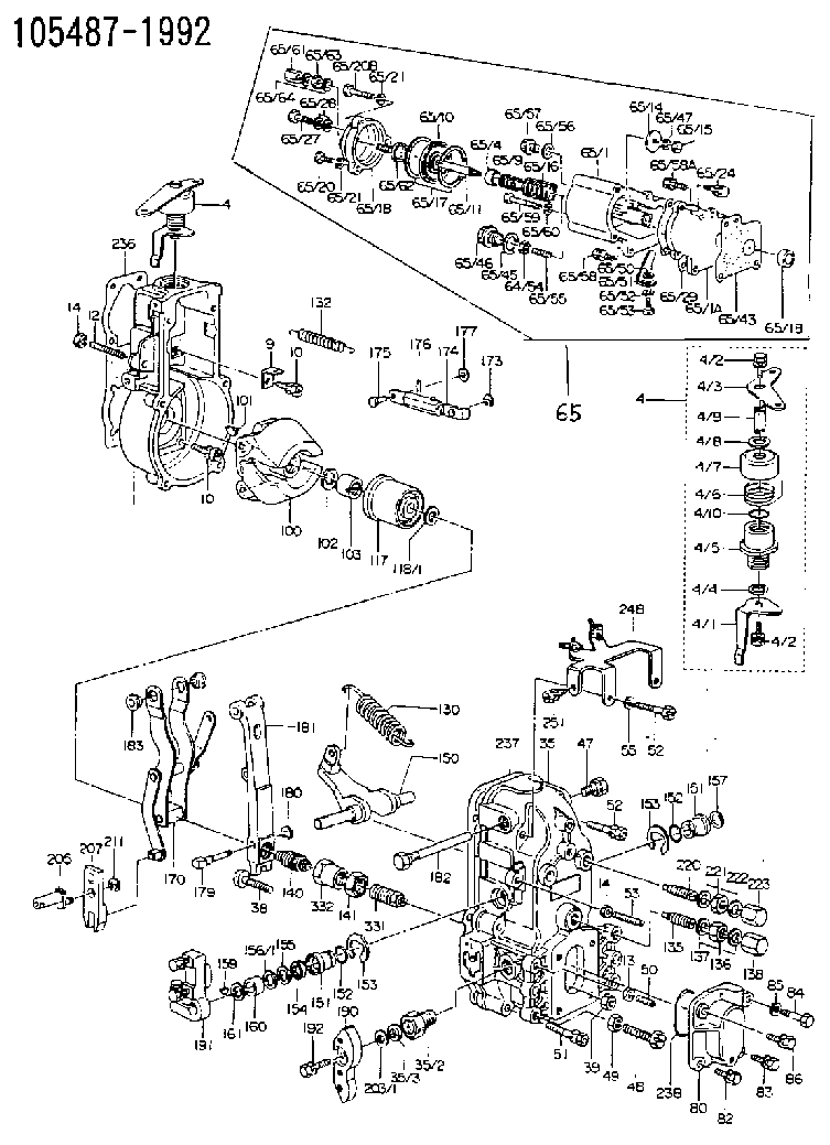
| 1. | [1] | 154000-4700 | GOVERNOR HOUSING |
| 4. | [1] | 154304-0920 | CONTROL LEVER |
| 4. | [1] | 154304-0920 | CONTROL LEVER |
| 4/1. | [1] | 154304-0100 | CONTROL LEVER |
| 4/2. | [2] | 154352-2000 | BLEEDER SCREW |
| 4/2. | [2] | 154352-2000 | BLEEDER SCREW |
| 4/3. | [1] | 154304-0900 | CONTROL LEVER |
| 4/4. | [1] | 029311-0230 | SHIM D18&10.3T0.5 |
| 4/5. | [1] | 154321-1500 | BUSHING |
| 4/6. | [1] | 154327-2901 | COILED SPRING |
| 4/7. | [1] | 154322-0100 | CAP |
| 4/8. | [1] | 029311-0220 | SHIM D18&10.3T0.2 |
| 4/9. | [1] | 154324-2700 | LEVER SHAFT |
| 4/10. | [1] | 029631-0030 | O-RING &9.8W2.3 |
| 9. | [1] | 154350-6000 | PLATE |
| 10. | [8] | 020106-2040 | BLEEDER SCREW M6P1L20 |
| 10. | [8] | 020106-2040 | BLEEDER SCREW M6P1L20 |
| 12. | [1] | 154010-0100 | FLAT-HEAD SCREW |
| 13. | [1] | 029240-6010 | UNION NUT M6P1.0H5* |
| 14. | [2] | 154011-0100 | HEXAGON NUT |
| 14. | [2] | 154011-0100 | HEXAGON NUT |
| 35. | [1] | 154514-1520 | GOVERNOR COVER |
| 35/2. | [1] | 154321-1800 | BUSHING |
| 35/3. | [1] | 029621-0080 | PACKING RING |
| 38. | [1] | 154031-3500 | FLAT-HEAD SCREW |
| 39. | [1] | 154011-1600 | UNION NUT |
| 47. | [1] | 154036-1200 | CAPSULE |
| 48. | [1] | 154010-5500 | BLEEDER SCREW M10P1.25L42 |
| 49. | [1] | 154011-2100 | UNION NUT |
| 50. | [1] | 155615-1100 | FLAT-HEAD SCREW M6P1.0L37 |
| 51. | [4] | 020106-3840 | BLEEDER SCREW |
| 52. | [2] | 029010-6850 | BLEEDER SCREW |
| 52. | [2] | 029010-6850 | BLEEDER SCREW |
| 53. | [1] | 154010-0100 | FLAT-HEAD SCREW |
| 55. | [2] | 014110-6440 | LOCKING WASHER |
| 65. | [1] | 154417-5421 | MANIFOLD-PRESSURE COMP. |
| 65/1. | [1] | 154412-0122 | GOVERNOR HOUSING |
| 65/1A. | [1] | 154412-0201 | SPACER BUSHING |
| 65/1B. | [1] | 134009-0000 | SPACER BUSHING |
| 65/4. | [1] | 154413-0500 | BUSHING |
| 65/9. | [1] | 154402-3900 | COILED SPRING |
| 65/10. | [1] | 154400-8220 | DIAPHRAGM |
| 65/11. | [1] | 154412-4101 | STOP PIN |
| 65/14. | [1] | 154406-5500 | SLOTTED WASHER |
| 65/15. | [1] | 013020-6040 | UNION NUT M6P1H5 |
| 65/16. | [1] | 154402-4800 | COILED SPRING |
| 65/17. | [2] | 154413-2600 | GASKET |
| 65/18. | [1] | 154404-5000 | COVER |
| 65/20. | [2] | 029010-6310 | BLEEDER SCREW |
| 65/20B. | [1] | 020106-4540 | BLEEDER SCREW M6P1.0L45 |
| 65/21. | [2] | 014110-6440 | LOCKING WASHER |
| 65/21. | [2] | 014110-6440 | LOCKING WASHER |
| 65/24. | [2] | 020106-2040 | BLEEDER SCREW M6P1L20 |
| 65/27. | [1] | 029731-0180 | EYE BOLT |
| 65/28. | [2] | 026510-1340 | GASKET D13.4&10.2T1 |
| 65/29. | [1] | 154390-2200 | GASKET |
| 65/43. | [1] | 154390-2300 | GASKET |
| 65/45. | [1] | 029331-8040 | GASKET |
| 65/46. | [1] | 154406-5800 | FLAT-HEAD SCREW |
| 65/47. | [1] | 014110-6440 | LOCKING WASHER |
| 65/50. | [1] | 154406-6800 | PLAIN WASHER |
| 65/51. | [1] | 154412-3900 | CONTROL LEVER |
| 65/52. | [1] | 014110-4440 | LOCKING WASHER |
| 65/53. | [1] | 010234-0820 | HEX-SOCKET-HEAD CAP SCREW |
| 65/54. | [1] | 013030-6040 | UNION NUT M6P1H3.6 |
| 65/55. | [1] | 154404-1500 | FLAT-HEAD SCREW L22.00 |
| 65/55B. | [1] | 154404-1600 | FLAT-HEAD SCREW L26.00 |
| 65/56. | [1] | 029331-2130 | GASKET |
| 65/57. | [1] | 154406-6500 | FLAT-HEAD SCREW |
| 65/58. | [2] | 020106-2840 | BLEEDER SCREW |
| 65/58A. | [1] | 020106-1440 | BLEEDER SCREW M6P1.0L14 |
| 65/59. | [1] | 010006-7040 | BLEEDER SCREW M6P1L70 |
| 65/60. | [1] | 014110-6440 | LOCKING WASHER |
| 65/61. | [1] | 154035-1600 | CAP NUT |
| 65/62. | [1] | 154404-4400 | FLAT-HEAD SCREW |
| 65/63. | [1] | 013030-6040 | UNION NUT M6P1H3.6 |
| 65/64. | [2] | 026506-1040 | GASKET D9.9&6.2T1 |
| 80. | [1] | 154060-7900 | COVER |
| 82. | [1] | 029020-6210 | BLEEDER SCREW |
| 83. | [1] | 020006-1640 | BLEEDER SCREW M6P1L16 4T |
| 84. | [1] | 029020-6220 | BLEEDER SCREW |
| 85. | [1] | 014110-6440 | LOCKING WASHER |
| 86. | [1] | 020006-1640 | BLEEDER SCREW M6P1L16 4T |
| 100. | [1] | 154100-9520 | FLYWEIGHT ASSEMBLY |
| 101. | [1] | 025803-1310 | WOODRUFF KEY |
| 102. | [1] | 029321-2020 | LOCKING WASHER |
| 103. | [1] | 029231-2030 | UNION NUT |
| 117. | [1] | 154123-2320 | SLIDING PIECE |
| 118/1. | [0] | 029311-0010 | SHIM D14&10.1T0.2 |
| 118/1. | [0] | 029311-0180 | SHIM D14&10.1T0.3 |
| 118/1. | [0] | 029311-0190 | SHIM D14&10.1T0.40 |
| 118/1. | [0] | 029311-0210 | SHIM D14&10.1T1 |
| 118/1. | [0] | 139410-0000 | SHIM D14.0&10.1T0.5 |
| 118/1. | [0] | 139410-0100 | SHIM D14.0&10.1T1.5 |
| 118/1. | [0] | 139410-3000 | SHIM D14&10.1T2.0 |
| 118/1. | [0] | 139410-3100 | SHIM D14&10.1T3.0 |
| 118/1. | [0] | 139410-3200 | SHIM D14&10.1T4.0 |
| 130. | [1] | 154150-6000 | GOVERNOR SPRING |
| 132. | [1] | 154154-4000 | COILED SPRING |
| 135. | [1] | 154158-0820 | HEADLESS SCREW |
| 136. | [1] | 029201-2290 | UNION NUT |
| 137. | [2] | 026512-1540 | GASKET D15.4&12.2T1.50 |
| 138. | [1] | 154159-1200 | CAP NUT |
| 140. | [1] | 154180-1620 | HEADLESS SCREW |
| 141. | [1] | 029201-6210 | UNION NUT |
| 150. | [1] | 154200-3701 | SWIVELLING LEVER |
| 151. | [1] | 154204-2001 | BUSHING |
| 151. | [1] | 154204-2001 | BUSHING |
| 152. | [2] | 029631-8020 | O-RING |
| 152. | [2] | 029631-8020 | O-RING |
| 153. | [2] | 154354-3900 | LOCKING WASHER |
| 153. | [2] | 154354-3900 | LOCKING WASHER |
| 154. | [1] | 139611-0000 | PACKING RING |
| 155. | [1] | 139411-0000 | SHIM |
| 156/1. | [0] | 029311-1110 | SHIM D17&11T0.1 |
| 156/1. | [0] | 029311-1120 | SHIM D17&11T0.2 |
| 156/1. | [0] | 029311-1130 | SHIM D17&11T0.3 |
| 157. | [1] | 154204-3400 | BUSHING |
| 159. | [1] | 025803-1310 | WOODRUFF KEY |
| 160. | [1] | 154206-0900 | BUSHING |
| 161. | [1] | 154206-0200 | PLAIN WASHER D19.5&11.2T1.0 |
| 170. | [1] | 154211-7220 | FORK LEVER |
| 173. | [1] | 016010-0540 | LOCKING WASHER |
| 174. | [1] | 154234-3520 | STRAP |
| 175. | [1] | 159231-4900 | BEARING PIN |
| 176. | [1] | 155402-3800 | SAFETY PIN |
| 177. | [1] | 029310-5170 | SHIM D8&5.3T0.5 |
| 179. | [1] | 154238-0301 | BEARING PIN |
| 180. | [1] | 016010-0540 | LOCKING WASHER |
| 181. | [1] | 154236-5300 | TENSIONING LEVER |
| 182. | [1] | 154237-0900 | BEARING PIN |
| 183. | [2] | 154237-0600 | BUSHING |
| 190. | [1] | 154360-2700 | CONTROL LEVER |
| 191. | [1] | 154340-0320 | CONTROL LEVER |
| 192. | [1] | 020006-1670 | BLEEDER SCREW M6P1L16 7T |
| 203/1. | [0] | 029311-0640 | SHIM D26.0&10.2T0.95 |
| 203/1. | [0] | 029311-0650 | SHIM D26.0&10.2T0.20 |
| 203/1. | [0] | 029311-0660 | SHIM D26.0&10.2T0.25 |
| 203/1. | [0] | 029311-0670 | SHIM D26.0&10.2T0.30 |
| 203/1. | [0] | 029311-0680 | SHIM D26.0&10.2T0.35 |
| 203/1. | [0] | 029311-0690 | SHIM D26.0&10.2T0.40 |
| 203/1. | [0] | 029311-0700 | SHIM D26.0&10.2T0.50 |
| 203/1. | [0] | 139410-1400 | SHIM D26&10.2T0.7 |
| 203/1. | [0] | 139410-1500 | SHIM D26&10.2T0.9 |
| 203/1. | [0] | 139410-1600 | SHIM D26&10.2T0.8 |
| 203/1. | [0] | 139410-2700 | SHIM D26&10.2T0.6 |
| 205. | [1] | 154324-3000 | LEVER SHAFT |
| 207. | [1] | 154326-0300 | CONTROL LEVER |
| 211. | [1] | 016010-0840 | LOCKING WASHER |
| 220. | [1] | 154050-1220 | HEADLESS SCREW |
| 221. | [1] | 029201-2140 | UNION NUT |
| 222. | [2] | 026512-1540 | GASKET D15.4&12.2T1.50 |
| 223. | [1] | 154159-1200 | CAP NUT |
| 236. | [1] | 154371-5600 | GASKET |
| 237. | [1] | 154390-0300 | GASKET |
| 238. | [1] | 029635-2020 | O-RING |
| 248. | [1] | 154316-9120 | BRACKET |
| 251. | [1] | 029010-6740 | BLEEDER SCREW |
| 331. | [1] | 154172-2820 | HEADLESS SCREW |
| 332. | [1] | 029201-6010 | UNION NUT |
| 900S. | [1] | 025803-1310 | WOODRUFF KEY |
| 901S. | [1] | 025803-1610 | WOODRUFF KEY |
Include in #1:
106691-0191
as GOVERNOR
Cross reference number
Zexel num
Bosch num
Firm num
Name
Information:
3T1888 Alternator 24V 50A (Delco-Remy Number 117248)
3T1888 Alternator1. Remove the covers from the end of the alternator to get access to the voltage regulator.
Delco-Remy Regulator Adjustment
(1) Potentiometer adjustment screw. (2) Transistor pins.2. Remove the rubber from the potentiometer so that the small screw can be seen.3. Connect a voltmeter across the batteries to measure the regulation of the voltage. The batteries must have a good charge for this measurement.4. Operate the alternator at medium speed for 30 seconds and take a measurement of the voltage. The voltage must be 27.5 1.0 volts. Turn the small screw counterclockwise to get less voltage output and clockwise to get more voltage output.5. After adjustment has been made, put a think layer of 3S6252 Silicone Rubber Sealant on the adjustment screw and install the covers. Make sure the location of the wires to the voltage regulator is not over the transistor pins. The transistor pins could make holes in the insulation for the wires and cause a short circuit.7N9720 Alternator 24V 35A (Bosch Number 0-122-469-001); 9G9538 Alternator 24V 50A (Bosch Number 0-122-469-002)
7N9720 AlternatorThe solid state regulator used with the Bosch Alternator is totally enclosed and non-adjustable. If the rate of charge is not correct a replacement of the regulator is necessary.9G4574 24V 35A (Nippondenso Number 100211-0860); 6T7223 24V 50A (Nippondenso Number 100211-0890)
9G4574 AlternatorNo adjustment can be made to change the rate of charge on the alternator regulator. If rate of charge is not correct, a replacement of the regulator is necessary.Starting System
Use the multimeter in the DCV range to find starting system components which do not function.Move the start control switch to activate the starter solenoid. Starter solenoid operation can be heard as the pinion of the starter motor is engaged with the ring gear on the engine flywheel.If the solenoid for the starter motor will not operate, it is possible that the current from the battery did not get to the solenoid. Fasten one lead of the multimeter to the connection (terminal) for the battery cable on the solenoid. Put the other lead to a good ground. A zero reading is an indication that there is a broken circuit from the battery. More testing is necessary when there is a voltage reading on the multimeter.The solenoid operation also closes the electric circuit to the motor. Connect one lead of the multimeter to the solenoid connection (terminal) that is fastened to the motor. Put the other lead to a good ground. Activate the starter solenoid and look at the multimeter. A reading of battery voltage shows the problem is in the motor. The motor must be removed for further testing. A zero reading on the multimeter shows that the solenoid contacts do not close. This is an indication of the need for repair to the solenoid or an adjustment to be made to the starter pinion clearance.Make a test with one multimeter lead fastened to the connection (terminal) for the small wire at the solenoid and the other lead to the