Information governor
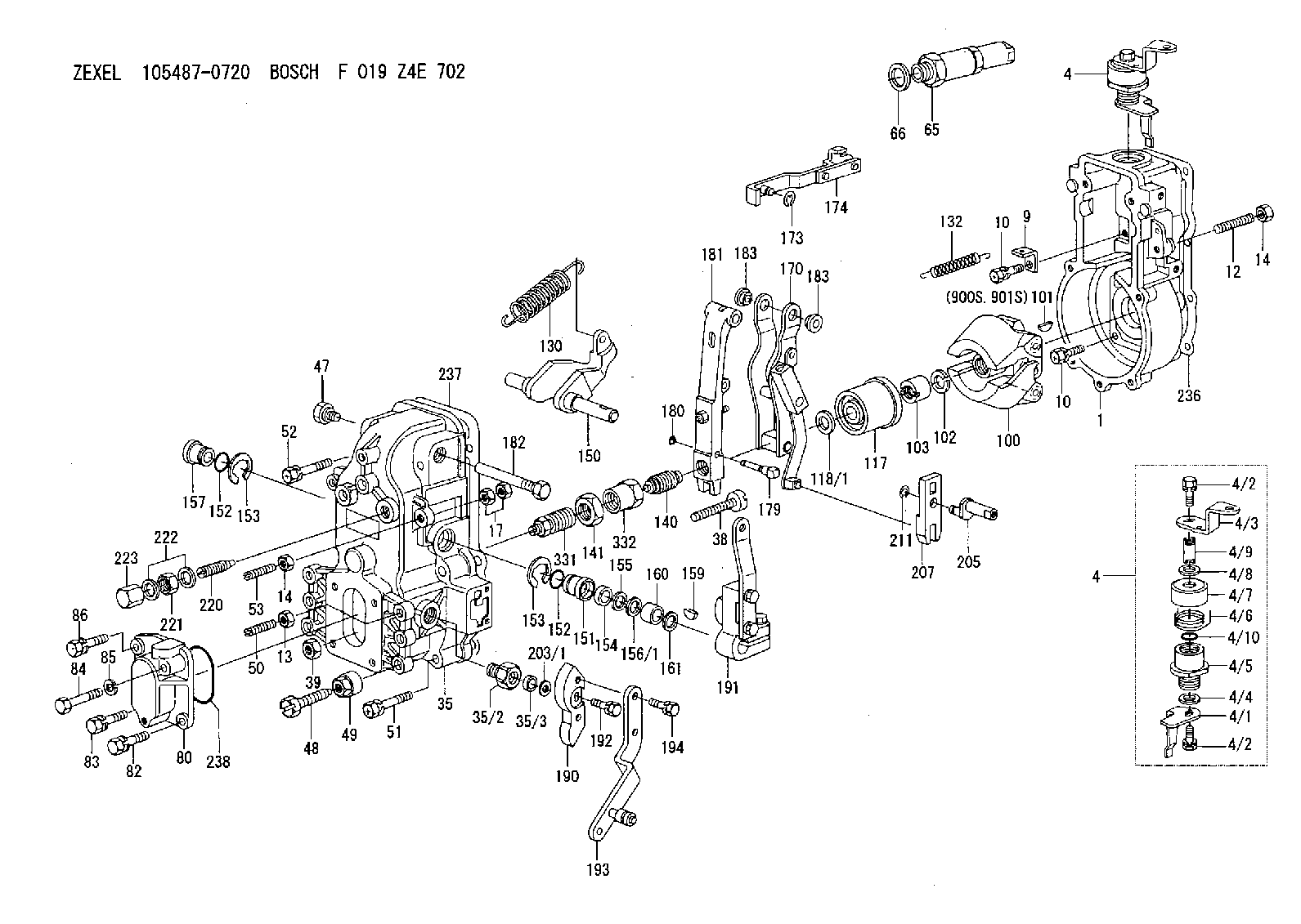
BOSCH
F 019 Z4E 702
f019z4e702
ZEXEL
105487-0720
1054870720
ISUZU
1157203700
1157203700
Rating:
Scheme ###:
| 1. | [1] | 154000-4700 | GOVERNOR HOUSING |
| 4. | [1] | 154364-0420 | CONTROL LEVER |
| 4. | [1] | 154364-0420 | CONTROL LEVER |
| 4/1. | [1] | 154304-6200 | CONTROL LEVER |
| 4/2. | [2] | 154352-2000 | BLEEDER SCREW |
| 4/2. | [2] | 154352-2000 | BLEEDER SCREW |
| 4/3. | [1] | 154364-0400 | CONTROL LEVER |
| 4/4. | [1] | 029311-0230 | SHIM D18&10.3T0.5 |
| 4/5. | [1] | 154321-1500 | BUSHING |
| 4/6. | [1] | 154327-2901 | COILED SPRING |
| 4/7. | [1] | 154322-0100 | CAP |
| 4/8. | [1] | 029311-0220 | SHIM D18&10.3T0.2 |
| 4/9. | [1] | 154324-2700 | LEVER SHAFT |
| 4/10. | [1] | 029631-0030 | O-RING &9.8W2.3 |
| 9. | [1] | 154350-6000 | PLATE |
| 10. | [8] | 020106-2040 | BLEEDER SCREW M6P1L20 |
| 10. | [8] | 020106-2040 | BLEEDER SCREW M6P1L20 |
| 12. | [1] | 154010-0100 | FLAT-HEAD SCREW |
| 13. | [1] | 029240-6010 | UNION NUT M6P1.0H5* |
| 14. | [2] | 154011-0100 | HEXAGON NUT |
| 14. | [2] | 154011-0100 | HEXAGON NUT |
| 17. | [2] | 154011-1100 | UNION NUT |
| 35. | [1] | 154513-1420 | GOVERNOR COVER |
| 35/2. | [1] | 154321-1800 | BUSHING |
| 35/3. | [1] | 029621-0080 | PACKING RING |
| 38. | [1] | 154031-3500 | FLAT-HEAD SCREW |
| 39. | [1] | 154011-1600 | UNION NUT |
| 47. | [1] | 154036-0300 | CAPSULE |
| 48. | [1] | 154010-5500 | BLEEDER SCREW M10P1.25L42 |
| 49. | [1] | 154011-2100 | UNION NUT |
| 50. | [1] | 155615-1100 | FLAT-HEAD SCREW M6P1.0L37 |
| 51. | [4] | 020106-3840 | BLEEDER SCREW |
| 52. | [2] | 020106-5040 | BLEEDER SCREW |
| 53. | [1] | 154010-0100 | FLAT-HEAD SCREW |
| 65. | [1] | 153043-4320 | STOPPING DEVICE |
| 66. | [1] | 026524-3040 | GASKET |
| 80. | [1] | 154060-7900 | COVER |
| 82. | [1] | 029020-6210 | BLEEDER SCREW |
| 83. | [1] | 020006-1640 | BLEEDER SCREW M6P1L16 4T |
| 84. | [1] | 029020-6220 | BLEEDER SCREW |
| 85. | [1] | 014110-6440 | LOCKING WASHER |
| 86. | [1] | 020006-1640 | BLEEDER SCREW M6P1L16 4T |
| 100. | [1] | 154100-9520 | FLYWEIGHT ASSEMBLY |
| 101. | [1] | 025803-1310 | WOODRUFF KEY |
| 102. | [1] | 029321-2020 | LOCKING WASHER |
| 103. | [1] | 029231-2030 | UNION NUT |
| 117. | [1] | 154123-0420 | SLIDING PIECE |
| 118/1. | [0] | 029311-0010 | SHIM D14&10.1T0.2 |
| 118/1. | [0] | 029311-0180 | SHIM D14&10.1T0.3 |
| 118/1. | [0] | 029311-0190 | SHIM D14&10.1T0.40 |
| 118/1. | [0] | 029311-0210 | SHIM D14&10.1T1 |
| 118/1. | [0] | 139410-0000 | SHIM D14.0&10.1T0.5 |
| 118/1. | [0] | 139410-0100 | SHIM D14.0&10.1T1.5 |
| 118/1. | [0] | 139410-3000 | SHIM D14&10.1T2.0 |
| 118/1. | [0] | 139410-3100 | SHIM D14&10.1T3.0 |
| 118/1. | [0] | 139410-3200 | SHIM D14&10.1T4.0 |
| 130. | [1] | 154150-7200 | GOVERNOR SPRING |
| 132. | [1] | 154154-0701 | COILED SPRING |
| 140. | [1] | 154175-1520 | HEADLESS SCREW |
| 141. | [1] | 029201-6010 | UNION NUT |
| 150. | [1] | 154200-3801 | SWIVELLING LEVER |
| 151. | [1] | 154204-2001 | BUSHING |
| 152. | [2] | 029631-8020 | O-RING |
| 152. | [2] | 029631-8020 | O-RING |
| 153. | [2] | 154354-3900 | LOCKING WASHER |
| 153. | [2] | 154354-3900 | LOCKING WASHER |
| 154. | [1] | 139611-0000 | PACKING RING |
| 155. | [1] | 139411-0000 | SHIM |
| 156/1. | [0] | 029311-1110 | SHIM D17&11T0.1 |
| 156/1. | [0] | 029311-1120 | SHIM D17&11T0.2 |
| 156/1. | [0] | 029311-1130 | SHIM D17&11T0.3 |
| 157. | [1] | 154204-3400 | BUSHING |
| 159. | [1] | 025803-1310 | WOODRUFF KEY |
| 160. | [1] | 154206-0900 | BUSHING |
| 161. | [0] | 154206-0200 | PLAIN WASHER D19.5&11.2T1.0 |
| 170. | [1] | 154211-7720 | GUIDE LEVER |
| 173. | [1] | 016010-0540 | LOCKING WASHER |
| 174. | [1] | 154230-4920 | STRAP |
| 179. | [1] | 154238-0301 | BEARING PIN |
| 180. | [1] | 016010-0540 | LOCKING WASHER |
| 181. | [1] | 154236-5300 | TENSIONING LEVER |
| 182. | [1] | 154237-0900 | BEARING PIN |
| 183. | [2] | 154237-0600 | BUSHING |
| 183. | [2] | 154237-0600 | BUSHING |
| 190. | [1] | 154360-8100 | CONTROL LEVER |
| 191. | [1] | 154341-6420 | CONTROL LEVER |
| 192. | [1] | 020006-1670 | BLEEDER SCREW M6P1L16 7T |
| 193. | [1] | 154362-5320 | CONTROL LEVER |
| 194. | [2] | 020006-1240 | BLEEDER SCREW M6P1L12 4T |
| 203/1. | [0] | 029311-0640 | SHIM D26.0&10.2T0.95 |
| 203/1. | [0] | 029311-0650 | SHIM D26.0&10.2T0.20 |
| 203/1. | [0] | 029311-0660 | SHIM D26.0&10.2T0.25 |
| 203/1. | [0] | 029311-0670 | SHIM D26.0&10.2T0.30 |
| 203/1. | [0] | 029311-0680 | SHIM D26.0&10.2T0.35 |
| 203/1. | [0] | 029311-0690 | SHIM D26.0&10.2T0.40 |
| 203/1. | [0] | 029311-0700 | SHIM D26.0&10.2T0.50 |
| 203/1. | [0] | 139410-1400 | SHIM D26&10.2T0.7 |
| 203/1. | [0] | 139410-1500 | SHIM D26&10.2T0.9 |
| 203/1. | [0] | 139410-1600 | SHIM D26&10.2T0.8 |
| 203/1. | [0] | 139410-2700 | SHIM D26&10.2T0.6 |
| 205. | [1] | 154324-3000 | LEVER SHAFT |
| 207. | [1] | 154326-0300 | CONTROL LEVER |
| 211. | [1] | 016010-0840 | LOCKING WASHER |
| 220. | [1] | 154050-6820 | HEADLESS SCREW |
| 221. | [1] | 029201-2140 | UNION NUT |
| 222. | [2] | 139512-0000 | GASKET D17.2&12.2T1.0 |
| 223. | [1] | 154159-1200 | CAP NUT |
| 236. | [1] | 154371-5600 | GASKET |
| 237. | [1] | 154390-0300 | GASKET |
| 238. | [1] | 029635-2020 | O-RING |
| 331. | [1] | 154179-2620 | HEADLESS SCREW |
| 332. | [1] | 029201-6220 | UNION NUT |
| 900S. | [1] | 025803-1310 | WOODRUFF KEY |
| 901S. | [1] | 025803-1610 | WOODRUFF KEY |
Include in #1:
106691-6581
as GOVERNOR
Cross reference number
Zexel num
Bosch num
Firm num
Name
Information:
1. Disconnect two Fuel lines (1).2. Remove four bolts (2) and remove fuel transfer pump and gasket. The following steps are for the installation of the fuel transfer pump.3. Position the gasket and fuel transfer pump then install bolts (2).4. Connect fuel lines (1).5. Prime the fuel system. See the MAINTENANCE MANUAL.Disassemble Fuel Transfer Pump
Start By:a. remove fuel transfer pump 1. Remove cover (1) from the fuel transfer pump. 2. Remove strainer (2). 3. Remove valve housing (3) from body (4). 4. Use a pencil grinder to remove the staked metal that holds inlet check valve (6) and outlet check valve (5) in place. Remove check valves (5) and (6). 5. Push the center of the diaphragm down and turn it 90° to disengage the actuator rod from the actuator arm. Remove diaphragm (7). 6. Remove spring (8). 7. Remove retainer (9). 8. Remove lever (12), shaft (11) and arm (10) as an assembly. 9. If necessary, remove washers (13) from shaft (11). Remove shaft (11) and separate arm (10) from lever (12). 10. If necessary, remove primer (14) and spring.11. Thoroughly inspect all parts of the fuel transfer pump. A repair kit is available to rebuild the fuel transfer pump. The following steps are for the assembly of the fuel transfer pump. 12. Install primer (14) and the spring on to body (4). 13. Install lever (12) into arm (10) and install pin (11) through the arm and lever. Put washer (13) on each side of arm (10). 14. Put spring (15) into position on the boss in body (4). Install arm (10) and lever (12) as an assembly into body (4). Be sure spring (15) engages with the tang on lever (12). 15. Install two retainers (9) to hold shaft (11) and arm and lever assembly in body (4). 16. Install spring (8) into body (4). 17. Install diaphragm (7) into body (4). Put the flat on the actuator rod in alignment with lever (12). Push the center of the diaphragm down and turn it 90° to engage the actuator rod with the actuator arm. 18. Install a gasket and check valve (6) and gasket and check valve (5) in valve body (3). Stake valve body (3) around each check valve to hold them in position. Make the stake marks at a different location than the original stake marks. 19. Put the valve body in place on diaphragm (7) and install the screws that hold it. 20. Put strainer (2) in position on valve body (3). 21. Install a new gasket in cover (1) and Install cover (1) on body.End By:a. install fuel transfer pump
Start By:a. remove fuel transfer pump 1. Remove cover (1) from the fuel transfer pump. 2. Remove strainer (2). 3. Remove valve housing (3) from body (4). 4. Use a pencil grinder to remove the staked metal that holds inlet check valve (6) and outlet check valve (5) in place. Remove check valves (5) and (6). 5. Push the center of the diaphragm down and turn it 90° to disengage the actuator rod from the actuator arm. Remove diaphragm (7). 6. Remove spring (8). 7. Remove retainer (9). 8. Remove lever (12), shaft (11) and arm (10) as an assembly. 9. If necessary, remove washers (13) from shaft (11). Remove shaft (11) and separate arm (10) from lever (12). 10. If necessary, remove primer (14) and spring.11. Thoroughly inspect all parts of the fuel transfer pump. A repair kit is available to rebuild the fuel transfer pump. The following steps are for the assembly of the fuel transfer pump. 12. Install primer (14) and the spring on to body (4). 13. Install lever (12) into arm (10) and install pin (11) through the arm and lever. Put washer (13) on each side of arm (10). 14. Put spring (15) into position on the boss in body (4). Install arm (10) and lever (12) as an assembly into body (4). Be sure spring (15) engages with the tang on lever (12). 15. Install two retainers (9) to hold shaft (11) and arm and lever assembly in body (4). 16. Install spring (8) into body (4). 17. Install diaphragm (7) into body (4). Put the flat on the actuator rod in alignment with lever (12). Push the center of the diaphragm down and turn it 90° to engage the actuator rod with the actuator arm. 18. Install a gasket and check valve (6) and gasket and check valve (5) in valve body (3). Stake valve body (3) around each check valve to hold them in position. Make the stake marks at a different location than the original stake marks. 19. Put the valve body in place on diaphragm (7) and install the screws that hold it. 20. Put strainer (2) in position on valve body (3). 21. Install a new gasket in cover (1) and Install cover (1) on body.End By:a. install fuel transfer pump