Information governor
BOSCH
F 019 Z1E 414
f019z1e414
ZEXEL
105487-0560
1054870560
MITSUBISHI
ME056062
me056062
Rating:
Scheme ###:
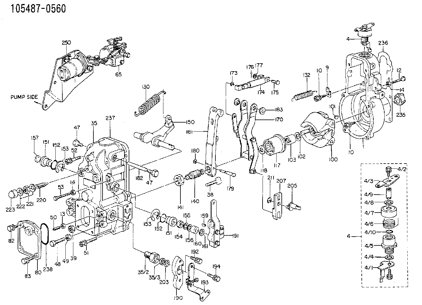
| 1. | [1] | 154000-5720 | GOVERNOR HOUSING |
| 4. | [1] | 154364-2420 | CONTROL LEVER |
| 4. | [1] | 154364-2420 | CONTROL LEVER |
| 4/1. | [1] | 154304-6200 | CONTROL LEVER |
| 4/2. | [2] | 154352-2000 | BLEEDER SCREW |
| 4/3. | [1] | 154364-2400 | CONTROL LEVER |
| 4/4. | [1] | 029311-0230 | SHIM D18&10.3T0.5 |
| 4/5. | [1] | 154321-1500 | BUSHING |
| 4/6. | [1] | 154327-2901 | COILED SPRING |
| 4/7. | [1] | 154322-0100 | CAP |
| 4/8. | [1] | 029311-0220 | SHIM D18&10.3T0.2 |
| 4/9. | [1] | 154324-2700 | LEVER SHAFT |
| 4/10. | [1] | 029631-0030 | O-RING &9.8W2.3 |
| 9. | [1] | 154350-6000 | PLATE |
| 10. | [8] | 020106-2040 | BLEEDER SCREW M6P1L20 |
| 10. | [8] | 020106-2040 | BLEEDER SCREW M6P1L20 |
| 12. | [1] | 154010-7300 | BLEEDER SCREW M8P1.25L60 |
| 13. | [1] | 029240-6010 | UNION NUT M6P1.0H5* |
| 14. | [1] | 154011-0100 | HEXAGON NUT |
| 14. | [1] | 154011-0100 | HEXAGON NUT |
| 14B. | [1] | 154011-2300 | UNION NUT |
| 35. | [1] | 154513-2020 | GOVERNOR COVER |
| 35/2. | [1] | 154321-1800 | BUSHING |
| 35/3. | [1] | 029621-0080 | PACKING RING |
| 38. | [1] | 154031-3500 | FLAT-HEAD SCREW |
| 39. | [1] | 154011-1600 | UNION NUT |
| 47. | [1] | 154036-0300 | CAPSULE |
| 47. | [1] | 154036-0300 | CAPSULE |
| 48. | [1] | 154010-7700 | BLEEDER SCREW M10P1.25L51 |
| 49. | [1] | 154011-2200 | UNION NUT |
| 50. | [1] | 155615-1900 | BLEEDER SCREW |
| 51. | [4] | 020106-3840 | BLEEDER SCREW |
| 52. | [2] | 020106-5040 | BLEEDER SCREW |
| 53. | [1] | 154010-3100 | BLEEDER SCREW |
| 65. | [1] | 154407-4220 | MANIFOLD-PRESSURE COMP. |
| 65/1. | [1] | 154408-6120 | GOVERNOR HOUSING |
| 65/1A. | [1] | 154408-2400 | SPACER BUSHING |
| 65/1B. | [1] | 134009-0000 | SPACER BUSHING |
| 65/2. | [2] | 021006-2240 | FLAT-HEAD SCREW |
| 65/3. | [1] | 020006-1640 | BLEEDER SCREW M6P1L16 4T |
| 65/4. | [1] | 029010-6220 | BLEEDER SCREW |
| 65/5. | [3] | 014110-6440 | LOCKING WASHER |
| 65/6. | [1] | 154408-1100 | CONTROL LEVER |
| 65/7. | [1] | 155004-2700 | LEVER SHAFT |
| 65/9. | [1] | 154400-4720 | STOP PIN |
| 65/10. | [0] | 029312-0180 | SHIM D25.5&20T0.5 |
| 65/10B. | [0] | 029312-0210 | SHIM D25.5&20T0.2 |
| 65/11. | [1] | 154403-7700 | COILED SPRING |
| 65/12. | [1] | 029300-8260 | PLAIN WASHER |
| 65/14. | [1] | 154400-0120 | DIAPHRAGM |
| 65/15. | [1] | 029340-8020 | GASKET |
| 65/16. | [1] | 029310-8560 | SHIM D14&8.4T0.7 |
| 65/17. | [1] | 013030-6040 | UNION NUT M6P1H3.6 |
| 65/18. | [1] | 154404-3100 | PLATE |
| 65/19. | [1] | 154404-3700 | COVER |
| 65/20. | [3] | 139006-0900 | BLEEDER SCREW |
| 65/20A. | [1] | 020106-2240 | BLEEDER SCREW |
| 65/21. | [1] | 023040-6040 | UNION NUT |
| 65/22. | [1] | 154404-1100 | FLAT-HEAD SCREW |
| 65/23. | [1] | 154035-0320 | CAP NUT |
| 65/24. | [1] | 026506-1040 | GASKET D9.9&6.2T1 |
| 65/25. | [1] | 029010-6010 | CAPSULE M6P1.0L7 |
| 65/26. | [2] | 026510-1340 | GASKET D13.4&10.2T1 |
| 65/28. | [1] | 029731-0180 | EYE BOLT |
| 65/32. | [1] | 020006-1640 | BLEEDER SCREW M6P1L16 4T |
| 65/33. | [1] | 029011-0120 | BLEEDER SCREW |
| 65/33A. | [1] | 026510-1340 | GASKET D13.4&10.2T1 |
| 65/34. | [1] | 154390-0800 | GASKET |
| 65/35. | [1] | 154390-0900 | GASKET |
| 65/40. | [1] | 155003-1700 | CONTROL LEVER |
| 65/41. | [1] | 155006-0700 | BLEEDER SCREW |
| 65/42. | [1] | 139608-0000 | PACKING RING |
| 65/43. | [0] | 029310-8040 | SHIM D13.5&8T0.2 |
| 65/43. | [0] | 029310-8050 | SHIM D13.5&8T0.5 |
| 65/44. | [2] | 029300-8320 | SHIM |
| 65/45. | [1] | 025520-1210 | SPLIT PIN |
| 65/46. | [1] | 155005-1900 | COILED SPRING |
| 65/47. | [1] | 154408-1700 | CONTROL LEVER |
| 65/48. | [1] | 014110-8440 | LOCKING WASHER |
| 65/49. | [1] | 013020-8140 | UNION NUT M8P1.25H6.5 |
| 65/50. | [1] | 154037-1900 | FLAT-HEAD SCREW |
| 65/51. | [1] | 154037-0500 | FLAT-HEAD SCREW |
| 65/52. | [2] | 154038-0200 | HEXAGON NUT |
| 65/53. | [3] | 154413-2600 | GASKET |
| 65/54. | [1] | 139505-0000 | PLAIN WASHER |
| 65/55. | [1] | 154354-5400 | BUSHING |
| 80. | [1] | 154060-4900 | COVER |
| 82. | [1] | 020006-1640 | BLEEDER SCREW M6P1L16 4T |
| 83. | [1] | 029020-6210 | BLEEDER SCREW |
| 84. | [1] | 020006-1640 | BLEEDER SCREW M6P1L16 4T |
| 86. | [1] | 029020-6210 | BLEEDER SCREW |
| 100. | [1] | 154100-9620 | FLYWEIGHT ASSEMBLY |
| 101. | [1] | 025803-1310 | WOODRUFF KEY |
| 102. | [1] | 029321-2020 | LOCKING WASHER |
| 103. | [1] | 029231-2030 | UNION NUT |
| 117. | [1] | 154123-2320 | SLIDING PIECE |
| 118/1. | [0] | 029311-0010 | SHIM D14&10.1T0.2 |
| 118/1. | [0] | 029311-0180 | SHIM D14&10.1T0.3 |
| 118/1. | [0] | 029311-0190 | SHIM D14&10.1T0.40 |
| 118/1. | [0] | 029311-0210 | SHIM D14&10.1T1 |
| 118/1. | [0] | 139410-0000 | SHIM D14.0&10.1T0.5 |
| 118/1. | [0] | 139410-0100 | SHIM D14.0&10.1T1.5 |
| 118/1. | [0] | 139410-3000 | SHIM D14&10.1T2.0 |
| 118/1. | [0] | 139410-3100 | SHIM D14&10.1T3.0 |
| 118/1. | [0] | 139410-3200 | SHIM D14&10.1T4.0 |
| 130. | [1] | 154150-6200 | GOVERNOR SPRING |
| 132. | [1] | 154154-1200 | COILED SPRING |
| 140. | [1] | 154178-2120 | HEADLESS SCREW |
| 141. | [1] | 029201-6010 | UNION NUT |
| 150. | [1] | 154200-3801 | SWIVELLING LEVER |
| 151. | [1] | 154204-2001 | BUSHING |
| 151. | [1] | 154204-2001 | BUSHING |
| 152. | [2] | 029631-8020 | O-RING |
| 152. | [2] | 029631-8020 | O-RING |
| 153. | [2] | 154354-3900 | LOCKING WASHER |
| 153. | [2] | 154354-3900 | LOCKING WASHER |
| 154. | [1] | 139611-0000 | PACKING RING |
| 155. | [1] | 139411-0000 | SHIM |
| 156/1. | [0] | 029311-1110 | SHIM D17&11T0.1 |
| 156/1. | [0] | 029311-1120 | SHIM D17&11T0.2 |
| 156/1. | [0] | 029311-1130 | SHIM D17&11T0.3 |
| 157. | [1] | 154204-3400 | BUSHING |
| 159. | [1] | 025803-1310 | WOODRUFF KEY |
| 160. | [1] | 154206-0900 | BUSHING |
| 161. | [0] | 154206-0200 | PLAIN WASHER D19.5&11.2T1.0 |
| 170. | [1] | 154216-2520 | GUIDE LEVER |
| 173. | [1] | 016010-0540 | LOCKING WASHER |
| 174. | [1] | 154230-5920 | STRAP |
| 175. | [1] | 159231-4900 | BEARING PIN |
| 176. | [1] | 155402-3800 | SAFETY PIN |
| 177. | [1] | 029310-5170 | SHIM D8&5.3T0.5 |
| 179. | [1] | 154238-0301 | BEARING PIN |
| 180. | [1] | 016010-0540 | LOCKING WASHER |
| 181. | [1] | 154236-5300 | TENSIONING LEVER |
| 182. | [1] | 154237-0900 | BEARING PIN |
| 183. | [2] | 154237-0600 | BUSHING |
| 190. | [1] | 154360-2800 | CONTROL LEVER |
| 191. | [1] | 154340-0120 | CONTROL LEVER |
| 192. | [1] | 020006-1670 | BLEEDER SCREW M6P1L16 7T |
| 193. | [1] | 154360-3820 | CONTROL LEVER |
| 194. | [2] | 020006-1240 | BLEEDER SCREW M6P1L12 4T |
| 203/1. | [0] | 029311-0640 | SHIM D26.0&10.2T0.95 |
| 203/1. | [0] | 029311-0650 | SHIM D26.0&10.2T0.20 |
| 203/1. | [0] | 029311-0660 | SHIM D26.0&10.2T0.25 |
| 203/1. | [0] | 029311-0670 | SHIM D26.0&10.2T0.30 |
| 203/1. | [0] | 029311-0680 | SHIM D26.0&10.2T0.35 |
| 203/1. | [0] | 029311-0690 | SHIM D26.0&10.2T0.40 |
| 203/1. | [0] | 029311-0700 | SHIM D26.0&10.2T0.50 |
| 203/1. | [0] | 139410-1400 | SHIM D26&10.2T0.7 |
| 203/1. | [0] | 139410-1500 | SHIM D26&10.2T0.9 |
| 203/1. | [0] | 139410-1600 | SHIM D26&10.2T0.8 |
| 203/1. | [0] | 139410-2700 | SHIM D26&10.2T0.6 |
| 205. | [1] | 154324-3000 | LEVER SHAFT |
| 207. | [1] | 154326-0300 | CONTROL LEVER |
| 211. | [1] | 016010-0840 | LOCKING WASHER |
| 220. | [1] | 154050-6220 | HEADLESS SCREW |
| 221. | [1] | 029201-2140 | UNION NUT |
| 222. | [2] | 026512-1540 | GASKET D15.4&12.2T1.50 |
| 223. | [1] | 154159-1200 | CAP NUT |
| 235. | [1] | 155412-5200 | IMPELLER WHEEL |
| 236. | [1] | 154371-5600 | GASKET |
| 237. | [1] | 154390-0300 | GASKET |
| 238. | [1] | 029635-2020 | O-RING |
| 250. | [1] | 154409-9620 | SOLENOID |
| 836S. | [1] | 154062-1700 | CAP D20L32 |
| 900S. | [1] | 025803-1310 | WOODRUFF KEY |
| 901S. | [1] | 025803-1610 | WOODRUFF KEY |
Include in #1:
106651-2041
as GOVERNOR
Cross reference number
Zexel num
Bosch num
Firm num
Name
105487-0560
F 019 Z1E 414
ME056062 MITSUBISHI
GOVERNOR
* K
* K
Information:
Fuel Filter Group
(1) Remove clips (1) and (2). Remove tube assembly (3) and elbow (4) from the fuel transfer pump on the replacement engine. Installation of new line is shown in Fuel Lines Group, Page 8.Fuel Tank Group
(1) Remove the fuel tank from the machine; see the Service Manual. (2) Fabricate boss (1) to the dimensions shown. Make 1/8" - 27 NPTF threads in one end. (3) Drill a 20.0 mm Ø (0.78" Ø) hole (A) through the bottom of the tank as shown. (4) Put boss (1) in hole (A) with the threaded end extending below the bottom of the full tank as shown. Make a 3.0 mm (0.12") fillet weld all around the boss.(5) Clean and install the fuel tank; see the Service Manual.Fuel Lines Group
(1) Remove fuel inlet hose (1) and tube assembly (2) from tube (A). (2) Install 307946 Elbow (3) and a 3J7354 Seal in the fuel transfer pump. Install 2V4869 Fitting (4) on elbow (3). Cut a 360.0 mm (14.17") length of 5P1465 Hose (5), and connect it to fitting (4) and tube assembly (A) with the former clamps.(3) Install 6D238 Valve Assembly (7) in the boss installed in the fuel tank (see Step 4, Page 7). Fasten 5G5681 Tube (8) to valve assembly (7). Use L2072 Clamp (9) to hold the other end of tube (8) in position. Install clamp (9) under bolt (10).(4) Install 307941 Elbow (11) and a 3J7354 Seal in the fuel return port of the fuel injection pump housing. Install 2V4869 Fitting (12) on elbow (11).(5) Cut a 520.0 mm (20.47") length of 5P1465 Hose (13), and connect it to fitting (12) and tube (8) with a 1P4278 Clamp (14). An optional step to the above procedure is to connect a 60.0 mm (2.36") length of 5P189 Tube to valve assembly (7). Cut a 2000.0 mm (78.75") length of 5P6442 Hose and connect it to 2V4869 Fitting (12) and to the 5P189 Tube with a 1P4278 Clamp. Tie the hose to the machine to prevent damage to the hose.Electrical System
(1) For all machines, connect the alternator wire of the harness to the alternator.(2) For machines 80U1-80U6734, remove the original voltage regulator. Put tape over the wire connection to the wiring harness so it will be out of the way. The alternator for this engine has a built in voltage regulator so the original voltage regulator is not needed for the electrical system.Flywheel Group (For Replacement of 7N9437, 1W163 or 2W7488 Engine Arrangements)
(1) Remove the flywheel from the new replacement engine.(2) Install a new 7W2290 Flywheel Assembly, and fasten it to the crankshaft with four T489 Bolts. See the Service Manual for the procedure and the bolt torque. If necessary, use of the former flywheel from the engine being replaced is acceptable.Installation Of Ether Starting Aid Group
The ether starting aid is no longer a required component of direct injection engine arrangements.(1) If the machine is equipped with an ether starting aid group, its reuse is optional. To reuse,
Have questions with 105487-0560?
Group cross 105487-0560 ZEXEL
Mitsubishi
Mitsubishi
105487-0560
F 019 Z1E 414
ME056062
GOVERNOR