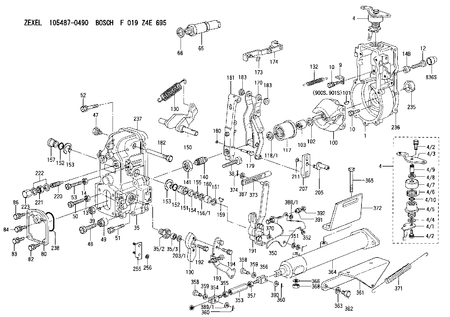
Information governor
BOSCH
F 019 Z4E 695
f019z4e695
ZEXEL
105487-0490
1054870490
MITSUBISHI
ME056061
me056061
Rating:
Scheme ###:
| 1. | [1] | 154000-5720 | GOVERNOR HOUSING |
| 4. | [1] | 154364-2420 | CONTROL LEVER |
| 4. | [1] | 154364-2420 | CONTROL LEVER |
| 4/1. | [1] | 154304-6200 | CONTROL LEVER |
| 4/2. | [2] | 154352-2000 | BLEEDER SCREW |
| 4/2. | [2] | 154352-2000 | BLEEDER SCREW |
| 4/3. | [1] | 154364-2400 | CONTROL LEVER |
| 4/4. | [1] | 029311-0230 | SHIM D18&10.3T0.5 |
| 4/5. | [1] | 154321-1500 | BUSHING |
| 4/6. | [1] | 154327-2901 | COILED SPRING |
| 4/7. | [1] | 154322-0100 | CAP |
| 4/8. | [1] | 029311-0220 | SHIM D18&10.3T0.2 |
| 4/9. | [1] | 154324-2700 | LEVER SHAFT |
| 4/10. | [1] | 029631-0030 | O-RING &9.8W2.3 |
| 9. | [1] | 154350-6000 | PLATE |
| 10. | [8] | 020106-2040 | BLEEDER SCREW M6P1L20 |
| 10. | [8] | 020106-2040 | BLEEDER SCREW M6P1L20 |
| 12. | [1] | 154010-7500 | BLEEDER SCREW M8P1.25L50 |
| 13. | [1] | 013020-6040 | UNION NUT M6P1H5 |
| 14. | [1] | 013020-8040 | UNION NUT M8P1.25H7 |
| 14B. | [1] | 154011-2300 | UNION NUT |
| 35. | [1] | 154513-1920 | GOVERNOR COVER |
| 35/2. | [1] | 154321-1800 | BUSHING |
| 35/3. | [1] | 029621-0080 | PACKING RING |
| 38. | [1] | 154031-3500 | FLAT-HEAD SCREW |
| 39. | [1] | 154011-1600 | UNION NUT |
| 47. | [1] | 154036-0300 | CAPSULE |
| 48. | [1] | 154010-7700 | BLEEDER SCREW M10P1.25L51 |
| 49. | [1] | 154011-2200 | UNION NUT |
| 50. | [1] | 155615-1900 | BLEEDER SCREW |
| 51. | [4] | 020106-3840 | BLEEDER SCREW |
| 52. | [2] | 020106-5040 | BLEEDER SCREW |
| 53. | [1] | 154010-7300 | BLEEDER SCREW M8P1.25L60 |
| 65. | [1] | 153020-4320 | STOPPING DEVICE |
| 66. | [1] | 026524-3040 | GASKET |
| 80. | [1] | 154060-4900 | COVER |
| 82. | [1] | 029020-6210 | BLEEDER SCREW |
| 83. | [1] | 020006-1640 | BLEEDER SCREW M6P1L16 4T |
| 84. | [1] | 029020-6210 | BLEEDER SCREW |
| 86. | [1] | 020006-1640 | BLEEDER SCREW M6P1L16 4T |
| 100. | [1] | 154100-9620 | FLYWEIGHT ASSEMBLY |
| 101. | [1] | 025803-1310 | WOODRUFF KEY |
| 102. | [1] | 029321-2020 | LOCKING WASHER |
| 103. | [1] | 029231-2030 | UNION NUT |
| 117. | [1] | 154123-2320 | SLIDING PIECE |
| 118/1. | [0] | 029311-0010 | SHIM D14&10.1T0.2 |
| 118/1. | [0] | 029311-0180 | SHIM D14&10.1T0.3 |
| 118/1. | [0] | 029311-0190 | SHIM D14&10.1T0.40 |
| 118/1. | [0] | 029311-0210 | SHIM D14&10.1T1 |
| 118/1. | [0] | 139410-0000 | SHIM D14.0&10.1T0.5 |
| 118/1. | [0] | 139410-0100 | SHIM D14.0&10.1T1.5 |
| 118/1. | [0] | 139410-3000 | SHIM D14&10.1T2.0 |
| 118/1. | [0] | 139410-3100 | SHIM D14&10.1T3.0 |
| 118/1. | [0] | 139410-3200 | SHIM D14&10.1T4.0 |
| 130. | [1] | 154150-8000 | GOVERNOR SPRING |
| 132. | [1] | 154154-0701 | COILED SPRING |
| 140. | [1] | 154178-4120 | HEADLESS SCREW |
| 141. | [1] | 029201-6010 | UNION NUT |
| 150. | [1] | 154200-3801 | SWIVELLING LEVER |
| 151. | [1] | 154204-2001 | BUSHING |
| 152. | [2] | 029631-8020 | O-RING |
| 152. | [2] | 029631-8020 | O-RING |
| 153. | [2] | 154354-3900 | LOCKING WASHER |
| 153. | [2] | 154354-3900 | LOCKING WASHER |
| 154. | [1] | 139611-0000 | PACKING RING |
| 155. | [1] | 139411-0000 | SHIM |
| 156/1. | [0] | 029311-1110 | SHIM D17&11T0.1 |
| 156/1. | [0] | 029311-1120 | SHIM D17&11T0.2 |
| 156/1. | [0] | 029311-1130 | SHIM D17&11T0.3 |
| 157. | [1] | 154204-3400 | BUSHING |
| 159. | [1] | 025803-1310 | WOODRUFF KEY |
| 160. | [1] | 154206-0900 | BUSHING |
| 161. | [0] | 154206-0200 | PLAIN WASHER D19.5&11.2T1.0 |
| 170. | [1] | 154216-2520 | GUIDE LEVER |
| 173. | [1] | 016010-0540 | LOCKING WASHER |
| 174. | [1] | 154230-4920 | STRAP |
| 179. | [1] | 154238-0301 | BEARING PIN |
| 180. | [1] | 016010-0540 | LOCKING WASHER |
| 181. | [1] | 154236-5300 | TENSIONING LEVER |
| 182. | [1] | 154237-0900 | BEARING PIN |
| 183. | [2] | 154237-0600 | BUSHING |
| 183. | [2] | 154237-0600 | BUSHING |
| 190. | [1] | 154360-2800 | CONTROL LEVER |
| 191. | [1] | 154345-7720 | CONTROL LEVER |
| 192. | [1] | 020006-1670 | BLEEDER SCREW M6P1L16 7T |
| 193. | [1] | 154361-3020 | CONTROL LEVER |
| 194. | [2] | 020006-1240 | BLEEDER SCREW M6P1L12 4T |
| 203/1. | [0] | 029311-0640 | SHIM D26.0&10.2T0.95 |
| 203/1. | [0] | 029311-0650 | SHIM D26.0&10.2T0.20 |
| 203/1. | [0] | 029311-0660 | SHIM D26.0&10.2T0.25 |
| 203/1. | [0] | 029311-0670 | SHIM D26.0&10.2T0.30 |
| 203/1. | [0] | 029311-0680 | SHIM D26.0&10.2T0.35 |
| 203/1. | [0] | 029311-0690 | SHIM D26.0&10.2T0.40 |
| 203/1. | [0] | 029311-0700 | SHIM D26.0&10.2T0.50 |
| 203/1. | [0] | 139410-1400 | SHIM D26&10.2T0.7 |
| 203/1. | [0] | 139410-1500 | SHIM D26&10.2T0.9 |
| 203/1. | [0] | 139410-1600 | SHIM D26&10.2T0.8 |
| 203/1. | [0] | 139410-2700 | SHIM D26&10.2T0.6 |
| 205. | [1] | 154324-3000 | LEVER SHAFT |
| 207. | [1] | 154326-0300 | CONTROL LEVER |
| 211. | [1] | 016010-0840 | LOCKING WASHER |
| 220. | [1] | 154050-6220 | HEADLESS SCREW |
| 221. | [1] | 029201-2130 | UNION NUT M12P1.0H6 |
| 222. | [2] | 026512-1540 | GASKET D15.4&12.2T1.50 |
| 223. | [1] | 154159-1200 | CAP NUT |
| 235. | [1] | 155412-5200 | IMPELLER WHEEL |
| 236. | [1] | 154371-5600 | GASKET |
| 237. | [1] | 154390-0300 | GASKET |
| 238. | [1] | 029635-2020 | O-RING |
| 255. | [1] | 154352-9420 | BRACKET |
| 256. | [2] | 029300-4050 | PLAIN WASHER |
| 350. | [1] | 154353-2320 | CONTROL LEVER |
| 351. | [1] | 014010-8140 | PLAIN WASHER D18&8.5T1.6 |
| 352. | [1] | 015316-1290 | SPLIT PIN |
| 353. | [1] | 154354-3800 | UNION NUT M6P1H30 |
| 354. | [1] | 154351-9300 | CLEVIS |
| 355. | [1] | 013020-6040 | UNION NUT M6P1H5 |
| 356. | [1] | 154351-9400 | CLEVIS |
| 357. | [1] | 029200-6210 | UNION NUT |
| 358. | [2] | 154351-9500 | BEARING PIN |
| 358. | [2] | 154351-9500 | BEARING PIN |
| 359. | [2] | 014010-6140 | PLAIN WASHER D13&6.5T1 |
| 359. | [2] | 014010-6140 | PLAIN WASHER D13&6.5T1 |
| 360. | [2] | 015316-1090 | SPLIT PIN |
| 360. | [2] | 015316-1090 | SPLIT PIN |
| 361. | [1] | 154354-6900 | BRACKET |
| 362. | [2] | 139016-0000 | BLEEDER SCREW |
| 363. | [2] | 014111-6440 | LOCKING WASHER |
| 364. | [1] | 154352-8920 | AIR CYLINDER |
| 365. | [2] | 010010-6540 | BLEEDER SCREW |
| 366. | [2] | 014111-0440 | LOCKING WASHER |
| 368. | [2] | 013021-0040 | UNION NUT M10P1.5H8 |
| 370. | [0] | 029310-8650 | SHIM D10.5&8.5T0.5 |
| 371. | [1] | 154314-8200 | COILED SPRING |
| 372. | [1] | 154355-0900 | BRACKET |
| 373. | [1] | 154352-4700 | STRAP |
| 374. | [1] | 015316-1290 | SPLIT PIN |
| 387. | [1] | 029310-7030 | SHIM D14.5&7T0.5 |
| 388/1. | [0] | 029300-6010 | PLAIN WASHER D11&6.4T0.8 |
| 388/1. | [0] | 029300-6020 | PLAIN WASHER D11&6.4T0.35 |
| 388/1. | [0] | 029300-6030 | PLAIN WASHER D11&6.4T0.5 |
| 388/1. | [0] | 029300-6040 | PLAIN WASHER D11&6.4T1 |
| 389/1. | [0] | 029300-6010 | PLAIN WASHER D11&6.4T0.8 |
| 389/1. | [0] | 029300-6020 | PLAIN WASHER D11&6.4T0.35 |
| 389/1. | [0] | 029300-6030 | PLAIN WASHER D11&6.4T0.5 |
| 389/1. | [0] | 029300-6040 | PLAIN WASHER D11&6.4T1 |
| 390. | [1] | 029310-8010 | PLAIN WASHER D15&8.4T0.2 |
| 391. | [0] | 154011-1400 | UNION NUT M6P1H15 |
| 392. | [0] | 013020-6040 | UNION NUT M6P1H5 |
| 836S. | [1] | 154062-1700 | CAP D20L32 |
| 900S. | [1] | 025803-1310 | WOODRUFF KEY |
| 901S. | [1] | 025803-1610 | WOODRUFF KEY |
Include in #1:
106671-2200
as GOVERNOR
Cross reference number
Zexel num
Bosch num
Firm num
Name
ME056061 MITSUBISHI
GOVERNOR
K 14JN MECHANICAL GOVERNOR GOV RFD GOV
K 14JN MECHANICAL GOVERNOR GOV RFD GOV
Information:
Test Points (Voltages And Waveforms)
dc Voltages Conditions: 1. dc input voltage applied to POWER connector as shown.2. CALIBRATION CHECK/OPERATE switch in the OPERATE position.3. Neither transducer connected to indicator.4. TPI is reference for all voltages.Equipment Required: 6V3030 Digital Multimeterdc Input Voltages Waveforms Conditions: 1. dc power input voltage of 25 1 Volts.2. CALIBRATION CHECK/OPERATE switch in the CHECK position (can be held in CHECK position with tape).3. Neither transducer connected to indicator.4. TPI is reference for all waveforms.Equipment Required: dc oscilloscope (dual channel preferred). Waveform Time Relationships
VOLTAGES MAY VARY 10%, PULSE DURATIONS BY 20% EXCEPT 2.66 ms WHICH IS BASED ON A 12.000 kHz OSCILLATOR FREQ. (1C202). SIGNAL SOURCE IS INTERNAL CALIBRATOR. ALL TEST POINTS REFERENCED TO TP1.Waveform Time Relationships (enlarged scale)
VOLTAGES MAY VARY 10%, PULSE DURATIONS BY 20% EXCEPT 83.3 ?s AND 2.66 ms WHICH ARE EXACT BASED ON A 12.000 kHZ OSCILLATOR. (1C202) SIGNAL SOURCE IS INTERNAL CALIBRATOR. ALL TEST POINTS REFERENCED TO TP1.Disassembly Procedure
1 Remove six screws (1) from front panel (2), and remove panel (2) from case (3). Remove four screws (4) from the PC board, and also remove the locknuts from the two front panel switches (5) and (6). Carefully lift front panel (2) from PC (printed circuit) board (7).Calibration Procedure
To make sure the 6V3100 Timing Indicator Group (1) has good accuracy, check its calibration at a minimum of every six months. Also, the timing indicator will need calibration if: A. It does not show 2000 30 R/MIN at (A) and 32.0 .2 DEG at (B), when the CALIBRATION CHECK-OPERATE Switch (C) is in the CALIBRATION CHECK position. With no input signal at (D) or (E), the reading at R/MIN location (A) must show three zeros (000). If four zeros (0000) show, it is an indication of a possible need for calibration of the unit. This error only is not reason enough to do a complete calibration procedure. It is also not necessary to do a complete calibration procedure if the reading at the DEG location (B) has a decimal point as shown, (00.0) in addition to the three zeros.B. Reading is different than (000) at either location (A) or (B).All calibrations can be done with the use of a small screwdriver, a frequency counter and