Information governor
BOSCH
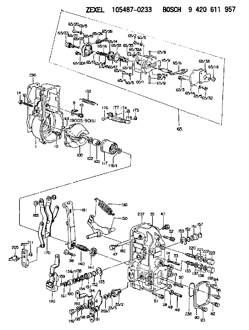
9 420 611 957
9420611957
ZEXEL
105487-0233
1054870233
NISSAN-DIESEL
1910196013
1910196013
Rating:
Scheme ###:
| 1. | [1] | 154000-8500 | GOVERNOR HOUSING |
| 9. | [1] | 154350-6000 | PLATE |
| 10. | [8] | 020106-2040 | BLEEDER SCREW M6P1L20 |
| 10. | [8] | 020106-2040 | BLEEDER SCREW M6P1L20 |
| 12. | [1] | 154010-0100 | FLAT-HEAD SCREW |
| 13. | [1] | 029240-6010 | UNION NUT M6P1.0H5* |
| 14. | [2] | 154011-0100 | HEXAGON NUT |
| 14. | [2] | 154011-0100 | HEXAGON NUT |
| 35. | [1] | 154512-6820 | GOVERNOR COVER |
| 35/2. | [1] | 154321-1800 | BUSHING |
| 35/3. | [1] | 029621-0080 | PACKING RING |
| 38. | [1] | 154031-3200 | FLAT-HEAD SCREW |
| 39. | [1] | 154011-1600 | UNION NUT |
| 47. | [2] | 154036-0300 | CAPSULE |
| 47. | [2] | 154036-0300 | CAPSULE |
| 48. | [1] | 154010-2300 | FLAT-HEAD SCREW |
| 49. | [1] | 029240-8000 | UNION NUT |
| 50. | [1] | 155615-1000 | FLAT-HEAD SCREW |
| 51. | [4] | 020106-3840 | BLEEDER SCREW |
| 52. | [2] | 020106-5040 | BLEEDER SCREW |
| 53. | [1] | 154010-0100 | FLAT-HEAD SCREW |
| 65. | [1] | 154407-2123 | MANIFOLD-PRESSURE COMP. |
| 65/1. | [1] | 154408-6020 | GOVERNOR HOUSING |
| 65/1A. | [1] | 154408-2400 | SPACER BUSHING |
| 65/1B. | [1] | 134009-0000 | SPACER BUSHING |
| 65/2. | [2] | 029010-6310 | BLEEDER SCREW |
| 65/3. | [1] | 020006-1640 | BLEEDER SCREW M6P1L16 4T |
| 65/4. | [1] | 029010-6220 | BLEEDER SCREW |
| 65/5. | [5] | 014110-6440 | LOCKING WASHER |
| 65/5. | [5] | 014110-6440 | LOCKING WASHER |
| 65/5. | [5] | 014110-6440 | LOCKING WASHER |
| 65/5. | [5] | 014110-6440 | LOCKING WASHER |
| 65/6. | [1] | 154408-1400 | CONTROL LEVER |
| 65/7. | [1] | 029405-0110 | BEARING PIN |
| 65/8. | [2] | 029140-8020 | CAPSULE |
| 65/8. | [2] | 029140-8020 | CAPSULE |
| 65/9. | [1] | 154400-4620 | STOP PIN |
| 65/10. | [0] | 029312-0180 | SHIM D25.5&20T0.5 |
| 65/10B. | [0] | 029312-0210 | SHIM D25.5&20T0.2 |
| 65/11. | [1] | 154411-6100 | COILED SPRING |
| 65/12. | [1] | 029300-8260 | PLAIN WASHER |
| 65/14. | [1] | 154400-7420 | DIAPHRAGM |
| 65/15. | [1] | 029310-8560 | SHIM D14&8.4T0.7 |
| 65/16. | [1] | 139505-0000 | PLAIN WASHER |
| 65/17. | [1] | 013030-6040 | UNION NUT M6P1H3.6 |
| 65/19. | [1] | 154404-5200 | COVER |
| 65/20. | [2] | 029010-6310 | BLEEDER SCREW |
| 65/20A. | [1] | 020106-2240 | BLEEDER SCREW |
| 65/21. | [1] | 023040-6040 | UNION NUT |
| 65/22. | [1] | 154404-1100 | FLAT-HEAD SCREW |
| 65/23. | [1] | 154035-0320 | CAP NUT |
| 65/26. | [2] | 026510-1340 | GASKET D13.4&10.2T1 |
| 65/28. | [1] | 029731-0120 | EYE BOLT |
| 65/32. | [1] | 020006-1640 | BLEEDER SCREW M6P1L16 4T |
| 65/33. | [1] | 029011-0120 | BLEEDER SCREW |
| 65/33A. | [1] | 026510-1340 | GASKET D13.4&10.2T1 |
| 65/34. | [1] | 154390-0800 | GASKET |
| 65/35. | [1] | 154390-0900 | GASKET |
| 65/53. | [2] | 154413-2600 | GASKET |
| 65/54. | [1] | 139308-0700 | LOCKING WASHER |
| 80. | [1] | 154060-4900 | COVER |
| 82. | [1] | 020006-1640 | BLEEDER SCREW M6P1L16 4T |
| 83. | [1] | 029020-6210 | BLEEDER SCREW |
| 84. | [1] | 020006-1640 | BLEEDER SCREW M6P1L16 4T |
| 86. | [1] | 029020-6210 | BLEEDER SCREW |
| 100. | [1] | 154100-5020 | FLYWEIGHT ASSEMBLY |
| 101. | [1] | 025803-1310 | WOODRUFF KEY |
| 102. | [1] | 029321-2020 | LOCKING WASHER |
| 103. | [1] | 029231-2030 | UNION NUT |
| 117. | [1] | 154123-0420 | SLIDING PIECE |
| 118/1. | [0] | 029311-0010 | SHIM D14&10.1T0.2 |
| 118/1. | [0] | 029311-0180 | SHIM D14&10.1T0.3 |
| 118/1. | [0] | 029311-0190 | SHIM D14&10.1T0.40 |
| 118/1. | [0] | 029311-0210 | SHIM D14&10.1T1 |
| 118/1. | [0] | 139410-0000 | SHIM D14.0&10.1T0.5 |
| 118/1. | [0] | 139410-0100 | SHIM D14.0&10.1T1.5 |
| 118/1. | [0] | 139410-3000 | SHIM D14&10.1T2.0 |
| 118/1. | [0] | 139410-3100 | SHIM D14&10.1T3.0 |
| 118/1. | [0] | 139410-3200 | SHIM D14&10.1T4.0 |
| 130. | [1] | 154150-6000 | GOVERNOR SPRING |
| 132. | [1] | 154154-4000 | COILED SPRING |
| 135. | [1] | 154157-5120 | HEADLESS SCREW |
| 136. | [1] | 029201-2130 | UNION NUT M12P1.0H6 |
| 137. | [2] | 026512-1540 | GASKET D15.4&12.2T1.50 |
| 138. | [1] | 154159-1200 | CAP NUT |
| 140. | [1] | 154170-7720 | HEADLESS SCREW |
| 141. | [1] | 029201-6010 | UNION NUT |
| 150. | [1] | 154200-3701 | SWIVELLING LEVER |
| 151. | [1] | 154204-2001 | BUSHING |
| 151. | [1] | 154204-2001 | BUSHING |
| 152. | [2] | 029631-8020 | O-RING |
| 152. | [2] | 029631-8020 | O-RING |
| 153. | [2] | 154354-3900 | LOCKING WASHER |
| 153. | [2] | 154354-3900 | LOCKING WASHER |
| 154. | [1] | 139611-0000 | PACKING RING |
| 155. | [1] | 139411-0000 | SHIM |
| 156/1. | [0] | 029311-1110 | SHIM D17&11T0.1 |
| 156/1. | [0] | 029311-1120 | SHIM D17&11T0.2 |
| 156/1. | [0] | 029311-1130 | SHIM D17&11T0.3 |
| 157. | [1] | 154204-3400 | BUSHING |
| 159. | [1] | 025803-1310 | WOODRUFF KEY |
| 160. | [1] | 154206-0900 | BUSHING |
| 161. | [0] | 154206-0200 | PLAIN WASHER D19.5&11.2T1.0 |
| 170. | [1] | 154210-7920 | FORK LEVER |
| 173. | [1] | 016010-0540 | LOCKING WASHER |
| 174. | [1] | 154230-5120 | STRAP |
| 176. | [1] | 159231-4900 | BEARING PIN |
| 177. | [1] | 155402-3800 | SAFETY PIN |
| 178. | [1] | 029310-5170 | SHIM D8&5.3T0.5 |
| 181. | [1] | 154236-1220 | TENSIONING LEVER |
| 182. | [1] | 154237-0400 | BEARING PIN |
| 183. | [2] | 154237-0600 | BUSHING |
| 190. | [1] | 154305-8320 | CONTROL LEVER |
| 191. | [1] | 154309-4520 | CONTROL LEVER |
| 192. | [1] | 154316-5600 | BLEEDER SCREW |
| 193. | [1] | 154301-7220 | CONTROL LEVER |
| 194. | [1] | 029301-2080 | SHIM D19&12.5T1 |
| 195. | [0] | 029301-2050 | SHIM D19&12.5T0.1 |
| 195B. | [0] | 029301-2060 | SHIM D19&12.5T0.2 |
| 195C. | [0] | 029301-2070 | SHIM D19&12.5T0.5 |
| 198. | [1] | 014110-8440 | LOCKING WASHER |
| 203/1. | [0] | 029311-0640 | SHIM D26.0&10.2T0.95 |
| 203/1. | [0] | 029311-0650 | SHIM D26.0&10.2T0.20 |
| 203/1. | [0] | 029311-0660 | SHIM D26.0&10.2T0.25 |
| 203/1. | [0] | 029311-0670 | SHIM D26.0&10.2T0.30 |
| 203/1. | [0] | 029311-0680 | SHIM D26.0&10.2T0.35 |
| 203/1. | [0] | 029311-0690 | SHIM D26.0&10.2T0.40 |
| 203/1. | [0] | 029311-0700 | SHIM D26.0&10.2T0.50 |
| 203/1. | [0] | 139410-1400 | SHIM D26&10.2T0.7 |
| 203/1. | [0] | 139410-1500 | SHIM D26&10.2T0.9 |
| 203/1. | [0] | 139410-1600 | SHIM D26&10.2T0.8 |
| 203/1. | [0] | 139410-2700 | SHIM D26&10.2T0.6 |
| 205. | [1] | 154324-1200 | LEVER SHAFT |
| 207. | [1] | 154326-0300 | CONTROL LEVER |
| 211. | [1] | 016010-0840 | LOCKING WASHER |
| 220. | [1] | 154050-1220 | HEADLESS SCREW |
| 221. | [1] | 029201-2140 | UNION NUT |
| 222. | [2] | 026512-1540 | GASKET D15.4&12.2T1.50 |
| 223. | [1] | 154159-1200 | CAP NUT |
| 236. | [1] | 154371-5600 | GASKET |
| 237. | [1] | 154390-0300 | GASKET |
| 238. | [1] | 029635-2020 | O-RING |
| 900S. | [1] | 025803-1310 | WOODRUFF KEY |
| 901S. | [1] | 025803-1610 | WOODRUFF KEY |
Cross reference number
Zexel num
Bosch num
Firm num
Name
105487-0233
1910196013 NISSAN-DIESEL
GOVERNOR
K 14JN MECHANICAL GOVERNOR GOV RFD GOV
K 14JN MECHANICAL GOVERNOR GOV RFD GOV
Information:
* NA: Naturally Aspirated* T: Turbocharged* TA: Turbocharged, Aftercooled* DI: Direct Injection* PC: Precombustion ChamberThis instruction gives the information needed to install a service replacement fuel injection pump and governor group for the above engines.1 Remove the fuel system from the engine. Make reference to the Service Manual for correct procedure.
When any replacement parts are put in the fuel system, the low idle, high idle and fuel setting must be checked and adjustments made as necessary. Only a mechanic with training in fuel system maintenance must be permitted to make these adjustments. The correct low idle and high idle rpm, and fuel setting are given in the FUEL SETTING INFORMATION.
2 Find and write down the serial number of the machine, the serial number of the engine and the engine arrangement number. All of these numbers are needed to find which parts to use for the fuel system reconditioning. 3 The chart that follows gives the part number of the governor spring (1) that is already installed in each Service Pump Group. Make reference to the FUEL SETTING INFORMATION, to find the part number of the governor spring needed for the fuel system reconditioning. If the governor spring must be changed, the chart for governor spring identification gives a method to find the correct governor spring. See the Service Manual for the procedure needed to change the governor spring. 4 The chart that follows gives the part number of the detent spring that is installed in the governor control of each service group. Look at the Parts Book for the specific engine or machine, to find which detent spring is needed for the fuel system reconditioning. If it is necessary to change detent spring (2), see the Service Manual for the procedure to install the detent spring. The illustrations with steps 4 and 5 show a 4 cylinder engine fuel system only; the procedure is the same for a 6 cylinder engine fuel system. 5 Make a comparison of side cover (3) on the new pump housing in the service group and the side cover on the old pump housing. If the side covers are different, they must be exchanged. The new pump housing must have the same type of side cover that is installed on the old pump housing. Use new gaskets when the side cover is exchanged. 6 Remove cover (4) from the new service group and the similar cover from the old fuel system. If the torque control groups are different, they must be exchanged. The torque control group on the new pump housing must be the same as the torque control group on the old pump housing. 7 The new service group has one bolt (5) and a stud (6) with nut (7) to fasten the torque control group in position. For those earlier fuel systems that had two bolts, similar to bolt (5), and did not have stud (6) and nut (7), use only the one bolt (5) and stud (6) with nut